Download presentation
Presentation is loading. Please wait.

1
ET5 June 2007 model answers

2
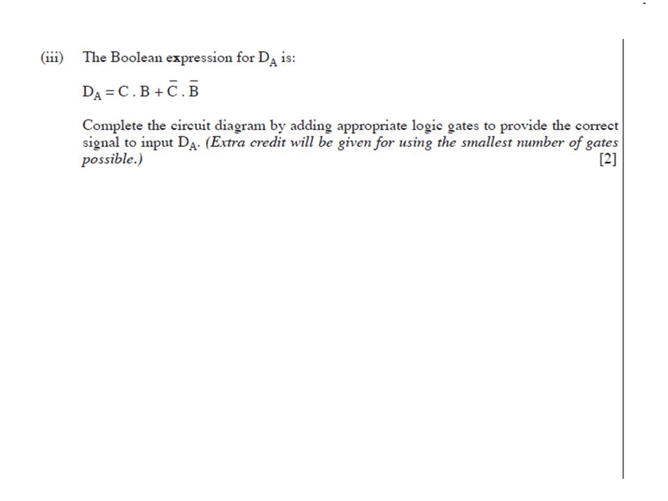
A.B A + C

5
0 0 0 0 1 0 0 1 1 1 1 0 0 0 1 1 1 1 1 0 0 1 0 1 S 6 ( 1 0 0) and S 7 ( 1 0 1) 0 1 0 0 1 1 1 1 0 0 0 1 1 1 1 0 0 0 0 0 1 A.C C A + B
 and S 7 ( 1 0 1) A.C C A + B")
6
R 2 = R 3 =R 4 1K (each produce the same voltage drop of 0.1v across their respective resistor) R 1 =2R 2, ie R 1 2K
 R 1 =2R 2, ie R 1 2K ")
7
10v 10v 10v 10v 10v 0v 0v 0v 0v The resolution is 0.1v

8
To convert from a 2 bit to 3bit output the number of comparators need to be increased from 3 to (2 n –1) comparators where n=3. The number of comparators therefore is 7. Also the number of resistors required will be one more than the number of comparators which gives 8. All other connections remain the same. However as the number of resistors has been increased and the ref voltage is still 0.5v then the resolution of the instrument will have increased.

9
Line regulation is a measure of the ability of the power supply to maintain a steady output voltage when the input line voltage changes. Load regulation is a measure of the ability of the output voltage to remain constant when the output current changes due to a change in the load.

10
A change in Vs will cause a change in V R but Vz will remain constant. Output voltage = Vz – 0.7v provided minimum zener current is maintained. As output current (I C ) increases this results in an increase in base current (I B ). However Vz will remain constant provided minimum zener current is maintained through the zener. Ie Vout = Vz- 0.7v
 increases this results in an increase in base current (I B ). However Vz will remain constant provided minimum zener current is maintained through the zener. Ie Vout = Vz- 0.7v.")
11
+ -

12
off on Be careful here as this is a negative pulse

13
V R = Vs –1.2v = 15 – 1.2 = 13.8v R = 13.8/100x10 -3 =138

14
15v 0v 0v 15v 0v -15v 30v

15
800K ( at least ten times the output impedance of the previous stage) 8 ( for max power transfer it must equal the input impedance of the next stage)
 8 ( for max power transfer it must equal the input impedance of the next stage)")
16
In this case max voltage transfer is required and therefore maximum input impedance and min output impedance. The non-inverting amplifier provides greater input impedance.

17
To maximise bandwidth both amplifiers must have equal gain ie each with a gain of 900 = 30 B/Width = G-B-width product /30 =1x10 6 /30 =33.3KHz (Only use the single gain of 30 of one of the amplifiers and not the product of 900)
")
18
The input impedance is approx H FE x R L = 60 x 8= 480

19
Output signal in phase with the input signal but displaced by – 0.7v

20
In the quiescent state where Vin is off the push pull amplifier does not dissipate energy while the emitter follower with DC biasing does.

21
Treble Cut F b =8KHz Break Frequency

22
From graph the gain of this filter at 1KHz is 20. Therefore the amplitude of the output is 1mV x 20 = 20mV

23
r C R 20 = R/r, therefore R = 20xr Let r 1K , R 20 K Or at the break R = 1/(2x xFbxC)=19.9K (NB I think the capacitor value in this question should be 1nFand not 0.1nF to get the correct answer)
=19.9K (NB I think the capacitor value in this question should be 1nFand not 0.1nF to get the correct answer)")
24
To be able to set a null voltage ie allows v out to be set to zero when both thermistors are at the same temperature.. This allows for slight differences in the thermistor characteristics. A B - + RFRF R1 R2 R3 V diff

25
V A ={12/(19.7 + 10.3)} x10.3 =4.12v V B = { 12/(20 + 10)}x 10 =4v V out =VB – VA =4 - 4.12 =-0.12v A device such as a sensitive centre-zero galvanometer/voltmeter. A positive deflection would indicate one thermistor is hotter, negative deflection would indicate that the other is hotter.

Similar presentations


 Analysis of ideal Op-Amp applications Comparison of.>")
 Deadline extended to 5pm Fridays, if.>")


 Analysis of ideal Op-Amp applications Comparison of ideal and non-ideal Op-Amp Non-ideal.>")