Download presentation
Presentation is loading. Please wait.

1
Wind Turbine Project Lift, Drag, Blade Aerodynamics & Power
Professor Christiani 11/10/14

2
Goals Grasp the physics behind a windturbine
Blade Element Theory Blade Momentum Theory Utilize MATLAB to model the physics Fill in the code Understand the syntax Obtain a plot for the coefficient of power So today, we will be discussing the physics of the windturbine. We will split up the lecture into two main parts: (1) Blade Element Theory and (2) Blade Momentum Theory. Blade Element Theory deals with the physics and how the wind forces the blades to turn. Blade Momentum theory deals with the turning action of the blades. In MATLAB, you will be given a code with several blanks in it. You will need to fill in the code in order to complete it. Learn to understand the syntax first, and then you will be able to fill in the blanks. Pay special attention to constants and how they are previously named! Ultimately, you will obtain a coefficient of power plot.
 Blade Element Theory and (2) Blade Momentum Theory. Blade Element Theory deals with the physics and how the wind forces the blades to turn. Blade Momentum theory deals with the turning action of the blades. In MATLAB, you will be given a code with several blanks in it. You will need to fill in the code in order to complete it. Learn to understand the syntax first, and then you will be able to fill in the blanks. Pay special attention to constants and how they are previously named! Ultimately, you will obtain a coefficient of power plot.")
3
Blade Element Theory So first, let’s discuss Blade Element Theory.

4
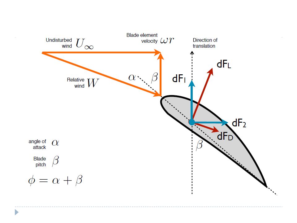
Lift and Drag FL FD Lift force perpendicular to airflow Drag force
Chord FD Lift force perpendicular to airflow Drag force parallel to the airflow Let’s analyze this diagram… ‘U’ is the wind speed approaching the airfoil. ‘Alpha’ is the angle at which the wind hits the blade. This is also called the “angle of attack.” The chord width is designated by the dashed line. ‘FL’ is the lift force, which occurs perpendicular to the wind. As the lift force increases, the wind turbine will experience more rotation. As the drag force increases, ‘FD’ is the drag force, which occurs parallel to the wind.

5
Airplane Angle of Attack
We can imagine these forces during an air flight as well. Pilots used the angle of attack to their advantage to help create lift while taking off. They also deploy flaps to increase drag during their decent.

6
What’s the difference between the blades?
Wind turbine Airplane Notice that an airplane’s wing is fixed, but a wind turbine’s blades are not. That is the greatest difference between both scenarios. The turbine’s blades rotate, but the airplane’s wing does not!

7
Calculating lift and drag
Power = (Force)(Velocity) Substitute for power provided by the wind geometric factor Let’s review some formulas that we know…Power is equal to a force times a velocity, which can be rearranged as such. We previously defined power as 1/2rhoAU^3. If we substitute this value in, we now have a new relationship for force. Resulting force generated on the airfoil
(Velocity) Substitute for power. provided by the wind. geometric factor. Let’s review some formulas that we know…Power is equal to a force times a velocity, which can be rearranged as such. We previously defined power as 1/2rhoAU^3. If we substitute this value in, we now have a new relationship for force. Resulting force generated. on the airfoil.")
8
Coefficients of lift and drag
Lift coefficient CL = how effectively the wing turns pressure into lift Drag force Drag coefficient CD = how much of the pressure is converted to drag

9
Coefficients of lift and drag
Geometric factors CD and CL Depend on: Airfoil shape Angle of attack Wing area Air speed Air density Empirically determined We will provide this for blades that are thin flat plates 5 10 15 20 25 30 0.25 0.50 0.75 1.00 1.25 1.50 1.75 Angle of Attack (degrees) Lift/Drag Coefficient lift coefficient drag Lift and drag dependent on the air density, air speed, wing area and angle of attack. These are empirically determined depending on the type of airfoil design.
 Lift/Drag Coefficient. lift. coefficient. drag. Lift and drag dependent on the air density, air speed, wing area and angle of attack. These are empirically determined depending on the type of airfoil design.")
10
Example: Lift Data Our data is obtained from a NACA airfoil 0012 profile with a Reynolds number of 80,000.

11
Piece-wise Function Equation for coefficient! Boundary Conditions!

12
Questions?

13
Harnessing wind energy
Can we capture all of this available wind?

14
How do we predict output power of wind turbine rotor?

15
Approach Need force at each point on the blade
Need angle of attack and wind velocity at each point on the blade Sum the equivalent forces Calculate the torque generated Calculate power generated

16
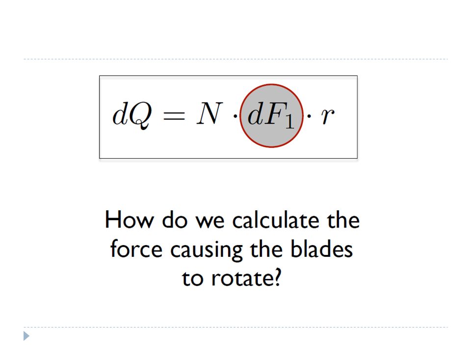
Blade Element Theory dF1
Blade divided into elements dr, on which momentum is applied Result is nonlinear equations that can be solved iteratively *Does not consider shed tip vortex. Some flow assumptions may breakdown for extreme conditions when flow becomes stalled (so you’ll see invalid data points for some values of angular velocity in the code!).
.")
25
Questions?

26
Blade Momentum Theory

27
Limits of the Formulation
As the number of blades (N) or chord width (c) increases, the blades will begin to overlap!
 or chord width (c) increases, the blades will begin to overlap!")
28
BET Limitation

29
Comparison Low σ, Low Q, High ω High σ, High Q, Low ω
Which type do you think you will build?

30
What is solidity? 𝜎= 𝑁𝑐 2𝜋𝑟
Defined as the percentage of the circumference of the rotor that contains material rather than air High-solidity Carry a lot of material Coarse blade angles Generate higher torques Low efficiency Low-solidity Less material = lower cost Generate lower torques High efficiency 𝜎= 𝑁𝑐 2𝜋𝑟

31
Blade Momentum Theory

32
Axial Induction Factor
Wind will diverge from linear path and span out. The wind must diverge from its original path in order to allow wind to pass through, between the blades. Fraction of wind source that is diverging True undisturbed wind

33
Radial Induction Factor
An analysis could be performed using Bernoulli’s equation on the fluid velocity, but we’re not going to derive it. Radial rotation of the wind causes the streamlines to diverge even further. This causes changes in the pressure drop across the rotor, which affects the way air flows through the plane and how the blades rotate. Streamlines from wind are rotating as blades rotate

34
Calculating a & a’

35
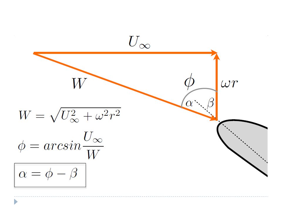
Inclusion of the Factors
What does W equal now? 𝑈 2 (1−𝑎) 2 + 𝑤 2 𝑟 2 (1+ 𝑎 ′ ) 2 What does φ equal now? arcsin 𝑈(1−𝑎) 𝑊
 2 + 𝑤 2 𝑟 2 (1+ 𝑎 ′ ) 2. What does φ equal now arcsin 𝑈(1−𝑎) 𝑊.")
36
Power Generated by Turbine and Coefficient Of Power
Sum torques of blade elements Power generated = (Torque)(Rotational velocity) Performance measure is the Coefficient of Power:
(Rotational velocity) Performance measure is the Coefficient of Power:")
37
Questions?

38
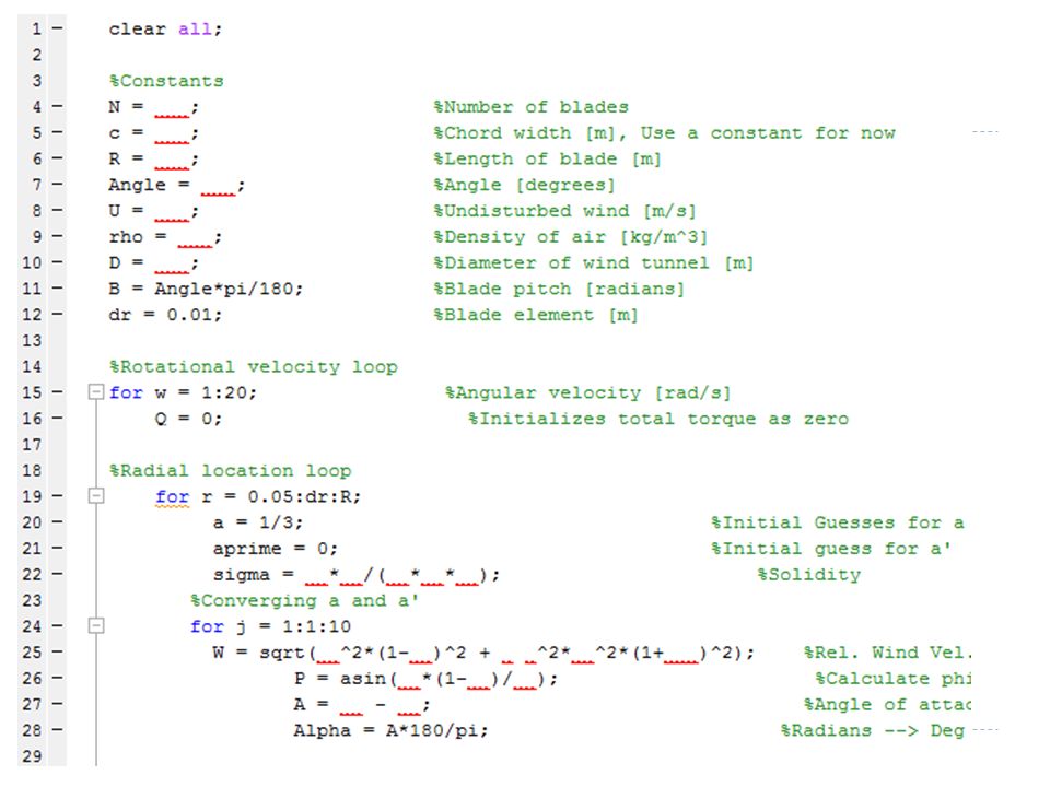
Code Review

41
Classwork MATLAB Fill in missing information Next steps
Download and review the provided MATLAB code and coefficients from excel file on PBworks Fill in missing information Basic constants CL and CD from plots Physics equations Plot Cp vs. ω Next steps Plan out process for parametrization Brainstorm ideas for blade shapes

Similar presentations


>")
 Selection of unique answer B) Brainstorming many ideas.>")


