Download presentation
Presentation is loading. Please wait.

1
MAHATMA GANDHI INSTITUTE OF TECHANICAL EDUCATION & RESERCH CENTER NAVSAR 130330119172 Tandel Parthav.R 130330119176 Tandel Sanket.D 140333119015 Patel Ashish. J 140333119017 Patel Hetal Kumar.T

2
Chapter 3 : PLASTIC DEFORMATION

3
Plastic Deformation It is the process in which shape and size or original dimension of the body, get changed due to application of forces or load. Deformation is of two types. 1. Plastic deformation 2. Elastic deformation

4
Elastic deformation disappears after removal of external forces or load, while plastic deformation remains constant. Plastic deformation is defined as the permanent deformation caused in a metal due to application of external load and which does not disappear after removal of the load.

5
Modes of deformation Slip Twinning Shear band formation

6
Slip Dislocations move on a certain crystallographic plane: slip plane Dislocations move in a certain crystallographic direction: slip direction The combination of slip direction and slip plane is called a slip system

7
Slip….. Slip planes are normally close-packed planes Slip directions are normally close-packed directions Recall for fcc close-packed planes are {111} Close-packed directions are

8
Slip systems

9
Twinning Common in hcp and bcc structures Limited deformation but help in plastic deformation in hcp and bcc crystals Occurs on specific twinning planes and twinning directions

10
Compare slip and twinning

11
Shear band formation Limited non-homogeneous deformation Very large localized strain ~1 or 100% Occurs especially under high strain rates Mechanism of deformation still unclear

12
Plastic deformation movement of dislocations Strengthening methods

13
Cold working Deformation at temperatures below 0.4 T m Dislocation density increases from 10 6 /cm 2 to 10 10-12 /cm 2 High dislocation density results in a large number of dislocation interactions which results in high strength and hardness

14
Solid solution strengthening Interaction between stress fields of alloy atoms and dislocations This is the purpose of alloying

15
Grain size refinement Small grains result in higher strength Small grains is equivalent to a large number of grain boundaries in the same volume Grain boundaries act as barriers to dislocation motion

16
Mechanism Strength is inversely proportional to grain size s = s 0 + k y d -1/2 Hall-Petch equation Smaller grains have more boundary area and hence more barriers to dislocation motion

17
Precipitation hardening Precipitates are second-phase particles Hard precipitates act as barriers to dislocation motion Applicable only to some alloy systems

18
Chapter 4 : Solidification of Metals and Alloy

19
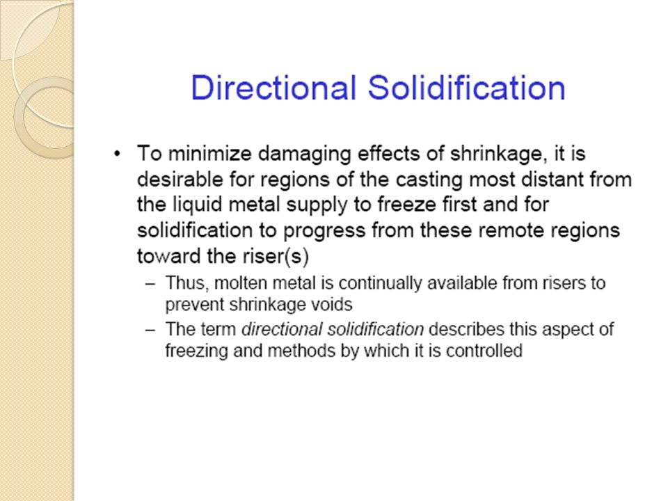
Introduction solidification or crystallization occurs when atoms are transformed from the disordered liquid state to the more ordered solid state, and is fundamental to metals processing. Directional solidification and progressive solidification are the types of solidification within castings.

20
Solidification of Pure Metals Temperature as a function of time for the solidification of pure metals. Note that the freezing takes place at a constant temperature. (b) Density as a function of time
 Density as a function of time.")
25
Solidification of Ingots and Castings

27
Chapter 12 : Non-Destructive Testing (NDT )
")
28
Types of NDT Visual Ultrasonic X-ray Thermographic Acoustic Emission Eddy Current Shearography

29
Visual Inspection Basic principle: – illuminate the test specimen with light – examine the specimen with the eye Used to: – to magnify defects which can not be detected by the unaided eye – to assist in the inspection of defects – to permit visual checks of areas not accessible to unaided eye Most widely used of all the nondestructive tests. Simple, easy to apply, quickly carried out and usually low in cost.

30
Visual Inspection Equipment Magnifying Glass Magnifying Mirror Microscope Borescope endoscopes or endoprobes Flexible Fiber Optic Borescope working lengths are normally 60 to 365 cm with diameters from 3 to 12.5 mm Video Imagescope

31
Ultrasonic Testing The use of ultrasonic waves to evaluate the condition of a material. Anomalies absorb or deflect the sound waves, which are then detected as changes in the waves. holes, delaminations, voids damage, debonds resin-rich, -poor areas

32
Ultrasonic Inspection High frequency sound waves are introduced into a material and they are reflected back from surfaces or flaws. Reflected sound energy is displayed versus time, and inspector can visualize a cross section of the specimen showing the depth of features that reflect sound. 0246810 plate crack

33
Ultrasonic Imaging High resolution images can be produced by plotting signal strength or time-of-flight using a computer-controlled scanning system.

34
Magnetic Particle Inspection The part is magnetized. Finely milled iron particles coated with a dye pigment are then applied to the specimen. These particles are attracted to magnetic flux leakage fields and will cluster to form an indication directly over the discontinuity. This indication can be visually detected under proper lighting conditions.

35
Magnetic Particle Crack Indications

36
A liquid with high surface wetting characteristics is applied to the surface of the part and allowed time to seep into surface breaking defects. The excess liquid is removed from the surface of the part. A developer (powder) is applied to pull the trapped penetrant out the defect and spread it on the surface where it can be seen. Liquid Penetrant Inspection
 is applied to pull the trapped penetrant out the defect and spread it on the surface where it can be seen. Liquid Penetrant Inspection.")
37
Radiography The radiation used in radiography testing is a higher energy (shorter wavelength) version of the electromagnetic waves that we see as visible light. The radiation can come from an X-ray generator or a radioactive source. High Electrical Potential Electrons - + X-ray Generator or Radioactive Source Creates Radiation Exposure Recording Device Radiation Penetrate the Sample

38
Film Radiography Top view of developed film X-ray film The part is placed between the radiation source and a piece of film. The part will stop some of the radiation. Thicker and more dense area will stop more of the radiation. = more exposure = less exposure The film darkness (density) will vary with the amount of radiation reaching the film through the test object.
 will vary with the amount of radiation reaching the film through the test object..")
39
Conductive material Coil Coil's magnetic field Eddy currents Eddy current's magnetic field Eddy Current Testing

41
Common Application of NDT Inspection of Raw Products Inspection Following Secondary Processing In-Services Damage Inspection

42
Machining Welding Grinding Heat treating Plating etc. Inspection Following Secondary Processing

43
Special Measurements Boeing employees in Philadelphia were given the privilege of evaluating the Liberty Bell for damage using NDT techniques. Eddy current methods were used to measure the electrical conductivity of the Bell's bronze casing at various points to evaluate its uniformity.

44
Pressure Vessel Inspection The failure of a pressure vessel can result in the rapid release of a large amount of energy. To protect against this dangerous event, the tanks are inspected using radiography and ultrasonic testing.

45
Summary Optical and Ultrasonic most widely used techniques. Each has different principles and uses.

Similar presentations


 Topic 7. Reading assignment Notes on Nondestructive Evaluation in the course website. Sec. 8.2, 8.3 and 8.4, William Callister,>")


 defects in sound conducting.>")
. Engineering Why use NDT? Components are not destroyed Can test for internal flaws Useful for valuable components.>")


