Download presentation
Presentation is loading. Please wait.

1
by Graham Woods School of Engineering, James Cook University graham.woods@jcu.edu.au

2
Contents Why do we need communications on the GBR? How do we implement communications on the GBR? Results from first EVER link. Conclusion

3
Introduction What is the problem? –The GBR is a large, remote and complex system. Would like to monitor; Coastal Runoff (fresh water, silt, fertilizer) Coral Bleaching (temperatures, light) Human Impact (fishing, shipping, security) Pests (Crown of thorns) Science (24-7 video footage) LOTS OF DATA eg 260Gb for 1month of video!
 Coral Bleaching (temperatures, light) Human Impact (fishing, shipping, security) Pests (Crown of thorns) Science (24-7 video footage) LOTS OF DATA eg 260Gb for 1month of video!.")
4
Introduction cont. How do we monitor now? –Fixed weather stations (HF radio links) BOM Link –Data loggers How will we monitor in the future? AIMS Automatic Weather Station (AWS) at Myrmidon Reef approximately 120km NNE of the City of Townsville, North Queensland (Australian Institute of Marine Science)
 BOM Link –Data loggers How will we monitor in the future. AIMS Automatic Weather Station (AWS) at Myrmidon Reef approximately 120km NNE of the City of Townsville, North Queensland (Australian Institute of Marine Science).")
5
Proposed Network Short Range Sensor Networks on Individual Reefs communicating with each other and the mainland via high speed links. X X X X X X X X X X X X X X X X X X

6
Base Node Central “hub” for sensor monitoring system Sensor nodes deployed around hub Nodes form wireless ad-hoc network.

7
How do we get data to mainland? ?

8
Communication Options OptionsSpeed (bps) Max. Range (km) Running Cost ($/day) Purchase Cost ($) Availability (%) Comments HF Radio6001000s<1<10,00095+Slow G3 phone4k (up)200<2<1,00099+Slowish Satellite9600200100-1000s<3,00099+Speed/ cost Microwave Link 10M+?200?<1<50,00090+?Purchase Cost
 Running Cost ($/day) Purchase Cost ($) Availability (%) Comments HF Radio s<1<10,00095+Slow G3 phone4k (up)200<2<1,00099+Slowish Satellite s<3,00099+Speed/ cost Microwave Link 10M+ 200 <1<50, Purchase Cost.")
9
Microwave Link ? Would provide high speed data transfer needed. BUT how could we achieve a range of 100km plus! Novel method “communications via the evaporation duct”

10
Conventional radio link – Standard Atmosphere Need 100m high towers!

11
Evaporation Duct Recall: Decreasing moisture content above the ocean surface trapping layer. “Evaporation duct height” – reflects the strength of the duct.

12
Ray Path Over Ocean Note : Signal trapping above ocean

13
Field predictions 2.5GHz5.5GHz 10.5GHz

14
Optimum Frequency and Antenna Height Optimum point: Freq = 10.5 GHz Height = 3.7 m

15
Proposed Microwave Link Location : Davies Reef to Australian Institute of Marine Science (AIMS) Operating Frequency : 10.5GHz ! Power : 1/2 W ! Range : 78 km! Height ASL : 5 m! Data rate : 10Mbps!

16
Predicted Link Operation Commercial System : emSolutions Ethermux F=10.6GHz, Pt = 27dBm, Gt=Gr=40dB, Estimated Path Loss 140dB, Signal Power: Bw = 20MHz, Ta = 300 kelvin. Noise Power: Signal to Noise Ratio = 77dB Link: Pr(dBm) = Pt(dBm) +Gt(dB) – PathLoss(dB) + Gr(dB) Pr(dBm) = 27 + 40 -140 + 40 = -33dBm Noise = k × Ta × Bw = -110dBm Pr
 = Pt(dBm) +Gt(dB) – PathLoss(dB) + Gr(dB) Pr(dBm) = = -33dBm Noise = k × Ta × Bw = -110dBm Pr.")
17
Trial Davies to AIMS Link Avg 170dB path loss, 15dB diurnal variation Tx Rx

18
Actual Link Davies Reef AIMS pump house

20
Measured Performance 20/21 th August 2007 16:30 to 16:30 30/31 st August, 2007 16:30 to 16:30 Min Path Loss = 167dB

21
Real Demonstration Web Camera on Davies Reef Realtime video feed, 10 frames/second. Web Cam

22
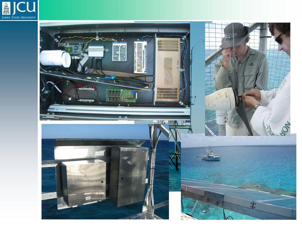
Practical Considerations

23
Fouling from sea birds is a major problem. Practical Considerations

24
Conclusion ☺ Worlds first high speed over ocean link to Great Barrier Reef. ☺ Enabling technology for reef monitoring. Path Loss more than predicted. Availability less than predicted

25
Questions? See www.ReefGrid.orgwww.ReefGrid.org

Similar presentations


 – P r (received power) P t (transmitted power) – P r (received power) Why calculating link loss?>")


 An Expert System for Near Real-Time Monitoring of Conditions Conducive to Coral Bleaching Jim Hendee Atlantic.>")


 Impact of spurious radiations.>")