Download presentation
Presentation is loading. Please wait.

1
Public Switched Telephone Network (PSTN)
")
2
Topics in PSTN Introduction review of early exchanges PSTN Standards User services & terminals (discuss today modems, phones and faxes) Modern exchange technology interface standards access and trunk networks signaling network management internetworking (telecommunications between networks)
 Modern exchange technology interface standards access and trunk networks signaling network management internetworking (telecommunications between networks)")
3
Introduction PSTN switching is based on circuit switching by duplex connections Temporary bidirectional connections Originally for speech (voice) only at 300-3400 Hz Earlier two subscribers connected by purely physical connection (physical switch contacts) Nowadays by time slots ~ ISDN is integrated to PSDN PCM is the TDMA standard for the digital transmission PCM time slots consist of 8 bit samples For voice digital exchange sets up 64 kbit/s connections Data connections by (1) modems, (2) ISDN interface (3) leased lines as X.25, or (4) ADSL PCM: pulse coded modulation
 only at Hz Earlier two subscribers connected by purely physical connection (physical switch contacts) Nowadays by time slots ~ ISDN is integrated to PSDN PCM is the TDMA standard for the digital transmission PCM time slots consist of 8 bit samples For voice digital exchange sets up 64 kbit/s connections Data connections by (1) modems, (2) ISDN interface (3) leased lines as X.25, or (4) ADSL PCM: pulse coded modulation")
4
History 1878 The first exchange constructed in La Porte, the US could connect any two of the 21 subscribers manual switching (!) 1891 first automatic exchange: Strowger Switch by Almon B. Strowger: an undertaker in Kansas City A 100 line Strowger switch: each user has its own selector no concentrators expensive

5
PSTN exchange development Register-controlled setup B-subscriber number receiver by a register register controls all the remaining call setup stages Distributed control Markers indicate idle switches Thus markers control path routing Stored program control, 1960s and 1970s (SPC) New services supervision charging gathering statistics Integrated charging Easier updating and maintenance 1960 and before
 New services supervision charging gathering statistics Integrated charging Easier updating and maintenance 1960 and before")
6
An early analog PBX: 100 subscriber exchange ( Subscriber controlled call set-up) Main parts of the switch: Call finders (CF), Group selectors (GS) and Line selectors (LS)
 Main parts of the switch: Call finders (CF), Group selectors (GS) and Line selectors (LS)")
7
An early exchange, call setup One of the 100 subscribers lifts his handset -> Call finder is activated to search the line. After the line is located other relays connect the dial-tone generator. The subscriber selects two digits. The first digit selects the subscriber group by using the group selector. The second digit selects the line selector. Selection is done by sending pulses that move the selectors stepwise. When connection is established a ringing tone is sent. Note that only 10 subscribers of 100 can call at the same time to different numbers!

8
Some features in PSTN of ´60 Coil loading was used to enhance higher frequency range Frequency division multiplexing with SSB was used in trunk networks

9
Some features of PSTN of ´60 (cont.) Network intelligence and value-added services not supported as such operators were anyhow intelligent :) value added services by tracking what happens in the area! Inter-exchange signaling call setup took about 15 seconds channel-associated signaling about 10% of trunk line capacity was taken by signaling Operation and maintenance using local info-bases and local workforce network maintenance was based on on-field check-ups

10
Twisted pair - digital line interface “per trunk signaling (local loop)”: - long setup time - hacking easy - voice grade circuits expensive
 : - long setup time - hacking easy - voice grade circuits expensive")
11
Basic telephone terminal A basic phone can be made by using just four units The bell The hook switch The keypad The speech circuit Modern keypads use dual-tone dialing The speech circuit adapts voice levels and isolates mic and speaker

12
Dual-tone dialing Dual-tone dialing is used in subscriber loop to transmit the selected B-subscriber number Earlier pulse selection was applied (very rare nowadays)
")
13
PSTN in ITU-T standards (www.itu.org) Series D Recommendations - General tariff principles Series E Recommendations - Overall network operation, telephone service, service operation and human factors Series G Recommendations - Transmission systems and media, digital systems and networks Series I Recommendations - Integrated services digital network (ISDN) Series M Recommendations - Network maintenance: international transmission systems, telephone circuits, telegraphy, facsimile, and leased circuits ITU: International Telecommunications Union
 Series M Recommendations - Network maintenance: international transmission systems, telephone circuits, telegraphy, facsimile, and leased circuits ITU: International Telecommunications Union")
14
More PSTN standards... Series O Recommendations - Specifications of measuring equipment Series P Recommendations - Telephone transmission quality, telephone installations, local line networks Series Q Recommendations - Switching and signaling Series V Recommendations - Data communication over the telephone lines

15
Example: G-recommendations:Transmission systems and media, digital systems and networks

16
E-Recommendations... (cont.) Sometimes recommendations may end up showing simple set of instructions in non-technical matters: Example: Recommendation E.134 (03/93) - Human factors aspects of public terminals: Generic operating procedures
 Sometimes recommendations may end up showing simple set of instructions in non-technical matters: Example: Recommendation E.134 (03/93) - Human factors aspects of public terminals: Generic operating procedures.")
17
Connecting into PSTN Users can connect into PSTN by Fixed-line phone (analog, voice) Cordless phone (analog with A/D converter in the terminal, also DECT based access) Fax (digital data with a build-in modem providing an analog signal) Computer (digital via modem, ISDN or ADSL techniques) Pay phone (analog or digital) PBX (PCM link to local exchange, A/D conversion in the business network) DECT: Digital Enhanced Cordless Telecommunications ADSL: Asynchronous Digital Subscriber Line PBX: Private Brach Exchange
 Cordless phone (analog with A/D converter in the terminal, also DECT based access) Fax (digital data with a build-in modem providing an analog signal) Computer (digital via modem, ISDN or ADSL techniques) Pay phone (analog or digital) PBX (PCM link to local exchange, A/D conversion in the business network) DECT: Digital Enhanced Cordless Telecommunications ADSL: Asynchronous Digital Subscriber Line PBX: Private Brach Exchange")
18
Modems ITU-T specifies several modem standards as V.26 (11/88) - 2400 bits per second modem for use on 4-wire leased lines V.27 (11/88) - 4800 bits per second modem for use on leased lines V.27ter (11/88) - 4800/2400 bits per second modem for use in the general switched telephone V.29 (11/88) - 9600 bits per second modem for use on point-to-point 4-wire leased lines V.90 (09/98) - 56 000 bit/s downstream and up to 33 600 bit/s upstream modem for use in the general switched telephone
 bits per second modem for use on 4-wire leased lines V.27 (11/88) bits per second modem for use on leased lines V.27ter (11/88) /2400 bits per second modem for use in the general switched telephone V.29 (11/88) bits per second modem for use on point-to-point 4-wire leased lines V.90 (09/98) bit/s downstream and up to bit/s upstream modem for use in the general switched telephone")
19
Basic modules of a modem Diagnostic unit Checks faults and controls the modem Interface and line units Adapt the modem and terminal Modem performs A/D and D/A conversion and select rate such that transmission quality criteria (error rate) can be meet Interface and check Mod. Demod. Diagnostics Line unit Line Computer

20
What is specified in a modem recommendation? Data signaling rates, symbol rates, carrier frequencies pre-emphasis, scrambler, framing, encoder Interface circuits Start-up signals and sequences Operating procedures Testing facilities There are two kind of modems specified by ITU-T: Digital modems: Generates G.711 signals and receives V.34 signals passed through a G.711 encoder. Connected to a digital switched network through a digital interface Analog modems: Generates V.34 signals and receives G.711 signals that have been passed through a G.711 decoder in an analog PSTN local loop G.711 (11/88) - Pulse code modulation (PCM) of voice frequencies V.34 (02/98) - A modem operating (up to 33 600 bit/s) for use in 2-wire analog PSTN
 - Pulse code modulation (PCM) of voice frequencies V.34 (02/98) - A modem operating (up to bit/s) for use in 2-wire analog PSTN.")
21
Example of a V.34 (33.6 kbit/s) connection
 connection")
22
Fax communications over PSTN Faxes follow standard PSTN modem communications recommendations or IEEE recommendations, as V.17 (02/91) (- Wire modem for facsimile applications with rates up to 14 400 bit/s) Faxes are divided into groups: Group 1 (´68): Analog scanning, 2400 bits/s Group 2 (´76): Analog scanning, 4800 bits/s Group 3 (´80): Digital scanning, 14400 bits/s Group 4 (´84): Digital scanning, 64 kbit/s (ISDN) Example of tasks of group 3 transmitting fax: Scanning Coding Compression Modem (D/A) Modified Huffman QAM, V.27ter/ V.29 A4/US letter, 1144 lines Gray scales by dithering
 (- Wire modem for facsimile applications with rates up to bit/s) Faxes are divided into groups: Group 1 (´68): Analog scanning, 2400 bits/s Group 2 (´76): Analog scanning, 4800 bits/s Group 3 (´80): Digital scanning, bits/s Group 4 (´84): Digital scanning, 64 kbit/s (ISDN) Example of tasks of group 3 transmitting fax: Scanning Coding Compression Modem (D/A) Modified Huffman QAM, V.27ter/ V.29 A4/US letter, 1144 lines Gray scales by dithering")
23
Connecting into PSTN: Equipment in the access network ISDN connection Twisted pair - connection Private Branch Exchange Multiplexer On-line subscriber with several telephones Business subscriber Wireless access (or radio access point) Distribution point Cross connection point
 Distribution point Cross connection point")
24
Connection of a remote subscriber stage Remote subscriber stage is connected directly to the group switch (to be soon discussed)
")
25
Local exchange ETC: Exchange terminal circuit Three-party calls, call waiting, broadcast Signaling (SS7) with users and other exchanges Traffic concentration Operation & maint. supp. services Charging Subscriber data Switch Control Switch Control

26
Subscriber stage To ETC ETC: Exchange terminal circuit

27
PSTN ISDN exchange interfaces (Q.512) NT:Network T. (ISDN T.)
 NT:Network T. (ISDN T.)")
28
Exchange interfaces and tasks, V1 Purpose of exchange is to organizes connection between exchange terminators! V1: Access to basic ISDN (This is user’s ISDN-U interface that can be used to connect small PBX also) Basic ISDN V1-functions: 2 B + D (2x64 kbps + 16 kbps) channeling structure timing and frame synchronization activate and deactivate terminator operation and maintenance feeding power supply
 Basic ISDN V1-functions: 2 B + D (2x64 kbps + 16 kbps) channeling structure timing and frame synchronization activate and deactivate terminator operation and maintenance feeding power supply.")
29
Exchange interfaces and tasks, V2-V4 V2: Interface serves typically concentrators 2048 kbit/s and 30 B + D Electrical Standard G.704 V3: Resembles V2 but intended for interface other exchanges V4:Interface to private networks

30
Exchange interfaces and tasks, V5 Between access network and exchange Specifies basic interfaces for Analog access ISDN-access Electrical interface G.703G.703 Channel control and signaling V5 supports interface rates 2048 kbit/s … 8448 kbit/s.

31
The space-switch Number of cross-connections reduced if a simple space division matrix of NxM (input x output) would be used Blocking possible Same signal can be routed via different paths: increased reliability
 would be used Blocking possible Same signal can be routed via different paths: increased reliability")
32
The time-switch One of the time slots of any full-duplex lines is connected to the line (at the time) Thus two switches / time slot connect a line For 100 full-duplex lines at 19.6 kbps a 1.92 Mbps bus is thus required for no blocking If no fixed assignment of input lines to time slot but on demand allocation -> blocking switch that reduces number of switches and switch clock frequency. For instance 200 devices of 19.6 kbps with bus of 2 Mbps -> about half of the devices can connect at any time

33
The time-space switch Works in local exchange and subscriber stage Performs PCM concentration 10:1 … 3:1 Connects subscribers to information tones and test equipment Time switch contains one bus for incoming and outgoing calls (full-duplex)
")
34
Connecting the local loop: Line interface circuit (LIC) Used for signaling in certain coin-operated pay-phones and PBX
 Used for signaling in certain coin-operated pay-phones and PBX")
35
Line interface circuit components Over-voltage protection Test equipment to connect to monitor the line condition faults Voltage feed ringing telephone current supply Detection of hook stage, pulse generated, or dual-tone receiver The hybrid junction (2 wire - 4 wire interface) An A/D converter (uses PCM techniques at 64 kbps)
 An A/D converter (uses PCM techniques at 64 kbps)")
36
The hybrid circuit 4-wire connection is used between exchanges and 2-wire connections from exchange to subscribers Two-wire

37
The hybrid-circuit If the impedance Z b equals the line impedance no incoming voice (down right) leaks to outgoing voice (up right) but the signal goes via the two wire connection on left To exchange From exchange Local loop
 leaks to outgoing voice (up right) but the signal goes via the two wire connection on left To exchange From exchange Local loop")
38
The hybrid circuit summarized The hybrid circuit transforms two-wire connection into 4- wire connection. If the hybrid is unbalanced echo will result Hybrid is balanced when no own voice is leaked into own loudspeaker Hybrid unbalance can result from line impedance changes due to weather conditions Unbalance results echo Echo cancellation circuits are harmful in data connections Nowadays realized by operational amplifier based circuitry that automatically monitors line impedance changes

39
Network echo suppressor (NES) R: transmission gate, A: attenuator, L: logic circuit When the signal is present on the receiving line the transmitting line is cut-off
 R: transmission gate, A: attenuator, L: logic circuit When the signal is present on the receiving line the transmitting line is cut-off")
40
Network echo canceller (NEC) Signal echo is extracted and subtracted from the received signal. More effective than echo suppressor. Often NEC and NES are however both used.

41
Exchange control functions summarized Maintenance functions supervision of subscriber lines and trunk circuits Operational functions Administrative data as subscriber database routing database Statistical data as from where and whom subscribers call holding times for different equipment types utilization of IN services The control function produces many exchange services:

42
Important exchange services summarized Traditional Absent-subscriber services as the answering machine Call booking: connection at the desired time Person-to-person call: ensures that call goes to a right person Serial call: setting up several calls Telephone conference: several persons participate simultaneously Directory inquiries: also speech recognition, recorded messages

43
Exchange services (cont.) Do not disturb (reply by recorded messages or tone) Wake-up/reminder Call forwarding: rerouting, variants: unconditional: all calls are rerouted forward when no reply forward when busy Callback: queued to the busy number, variants: busy line callback no answer callback Last number redial Remote control of services: other phone is used to program services to customers own phone
 Do not disturb (reply by recorded messages or tone) Wake-up/reminder Call forwarding: rerouting, variants: unconditional: all calls are rerouted forward when no reply forward when busy Callback: queued to the busy number, variants: busy line callback no answer callback Last number redial Remote control of services: other phone is used to program services to customers own phone")
44
PSTN operation and maintenance Different alarm classes Vital functions and circuits (as SS7 and group switch) may use secured paths and backups Programs provided for: troubleshooting fault diagnostics hardware faults can be isolated Supervision is realized also by connecting maintenance units to the network A supervision plan by network levels:
 may use secured paths and backups Programs provided for: troubleshooting fault diagnostics hardware faults can be isolated Supervision is realized also by connecting maintenance units to the network A supervision plan by network levels:")
45
Modern PSTN hierarchy

46
PSTN Hierarchy cont. Local (example, within Espoo) Subscriber connections Switching within the local exchange Switching to other exchanges Transit (within Finland, say between Tampere and Helsinki) Switching traffic between different geographical areas within one country International Gateway-type traffic between different countries different operators
 Subscriber connections Switching within the local exchange Switching to other exchanges Transit (within Finland, say between Tampere and Helsinki) Switching traffic between different geographical areas within one country International Gateway-type traffic between different countries different operators.")
47
PSTN basic call routing Phase 1: The A-subscriber lifts the handset Phase 2: The exchange receives B-subscriber number Phase 3: The exchange sets up the outgoing call Phase 4: The subscribers concludes the call

48
Phase 1: The A-subscriber lifts the handset Subscribers’ lines are scanned and off-hook is detected Subscriber database checked for sending the dial-tone (depends on service class as for instance are the outgoing calls allowed) Memory reserved for the number to be dialed in the control system A tone receiver for the dual-tone dialing signaling is connected through the time switch in the subscriber stage The dial tone is sent
 Memory reserved for the number to be dialed in the control system A tone receiver for the dual-tone dialing signaling is connected through the time switch in the subscriber stage The dial tone is sent")
49
Phase 2: The exchange receives B- subscriber number If dual-tone dialing is used Tone receiver sends the received B subscriber number to the control function If pulses are used They are interpreted by the line interface circuit The control system decides: Where the call is going (under same or another exchange) Which charging method is used time of the day, weekday, billing agreements, B- subscriber number What will be the length of the number
 Which charging method is used time of the day, weekday, billing agreements, B- subscriber number What will be the length of the number")
50
Phase 2: B-number at the same exchange or at a different exchange? At the same exchange: Query to subscriber database: is the subscriber banned for incoming calls? is the subscriber entitled for the service he is using? is the user in “call diversion unconditional” or “call waiting” status At a different exchange: perform routing analysis depends on user category, time of the day

51
Phase 3: The exchange sets up the outgoing call When the analysis is finished, an outgoing time slot is reserved in the group switch Exchange starts signaling the next exchange If SS7 is used signaling takes different bearer net that the call (Common ch. signaling) Call path is selected based on congestion condition was B-subscriber line reserved? When B is free the B-subscriber exchange signals: “B- subscriber free”
 Call path is selected based on congestion condition was B-subscriber line reserved. When B is free the B-subscriber exchange signals: B- subscriber free .")
52
Phase 3: The exchange sets up the outgoing call (cont.) The control function orders the group switch to reserve a PCM time slot for A and B subscribers at the outgoing PCM link The dual-tone receiver is disconnected The subscribers are connected to the correct time slot The B-subscriber exchange send a ringing tone to B and the respective tone to A-subscriber The control function starts to monitor the call for charging for observing when the call is about to end
 The control function orders the group switch to reserve a PCM time slot for A and B subscribers at the outgoing PCM link The dual-tone receiver is disconnected The subscribers are connected to the correct time slot The B-subscriber exchange send a ringing tone to B and the respective tone to A-subscriber The control function starts to monitor the call for charging for observing when the call is about to end")
53
Phase 4: The subscribers concludes the call The call can be concluded by the A or B subscriber If A closes first the call is concluded immediately If B closes first a timeout is applied (usually 90 seconds) When the call is terminated the control function tells the charging to be stopped frees the circuits and timeslots reserved for the call in the pathway by using a signaling system
 When the call is terminated the control function tells the charging to be stopped frees the circuits and timeslots reserved for the call in the pathway by using a signaling system")
54
Subscriber signaling flowchart

55
Subscriber signaling for a fax

56
Subscriber signaling for a fax (cont.)
")
57
Inter exchange signaling Channel associated signaling (CAS) as No.5, R1, R2 analog and digital connections Modern ISDN exchanges apply SS7(digital), that is a common channel signaling method (CSS) that is discussed later in its own lecture CAS is divided into line and register signaling: Line signaling: line state between the trunk-links as answer, clear-forward, clear-back Register signaling: routing information as B-number, A-category, B-status
 as No.5, R1, R2 analog and digital connections Modern ISDN exchanges apply SS7(digital), that is a common channel signaling method (CSS) that is discussed later in its own lecture CAS is divided into line and register signaling: Line signaling: line state between the trunk-links as answer, clear-forward, clear-back Register signaling: routing information as B-number, A-category, B-status")
58
Inter exchange signaling (cont.) Three categories of information is transmitted: setup, supervision clearing service related information as forwarding, callback, charging status change information transmission network congestion neighborhood exchange congestion
 Three categories of information is transmitted: setup, supervision clearing service related information as forwarding, callback, charging status change information transmission network congestion neighborhood exchange congestion")
59
Example of inter-exchange signaling

60
Inter-exchange signaling (cont.)
")
61
Alternative routing Different PSTN traffic types, phone, fax and data require different properties from the transmission media Hence they are sometimes routed via different routes Exchange makes analysis based on B-subscriber number which route is to be selected In dynamic routing exchange “learns” from its mistake if a direct connection is available it is selected first if too much congestion is encountered then the last successful route is selected Alternative routing aims to utilize network capacity better than load sharing

62
Load sharing Dedicated exchanges are connected via fixed, different rate connections

63
Alternative routing (cont.) The H (high congestion route is the first choice) The alternatives: A1-B1, A1-B2-B1, A1-A2-B2-B1, A1-A2- B3-B2-B1,A1-A2-A3-B3-B2-B1
 The H (high congestion route is the first choice) The alternatives: A1-B1, A1-B2-B1, A1-A2-B2-B1, A1-A2- B3-B2-B1,A1-A2-A3-B3-B2-B1")
64
Leased lines are used in semi-permanent and secured routing plans Advantages: predictable quality, low price provided service is used, high availability Disadvantages: First setting up can take weeks, high price if the customer cannot predict usage Restricted (but guaranteed!) line capacity
 line capacity")
65
A case study: DX 200 Exchange Various control units apply common busses to control the exchange

66
A case study: DX 200 Exchange SSU: Subscriber Signaling Unit: controls access network CCSU:Common Channel Signaling Unit (SS7). CCMU: Common Channel Signaling Management Unit: (as MTP, SCCP) PAU: Primary Rate Access Unit: controls basic (64 kbit/s) system interfaces LSU: Line Signaling Unit: takes care of signaling between transit exchanges and access networks MFSU: MULti-frequency Service Unit: Takes care of signaling when multiple frequency signals are used
 PAU: Primary Rate Access Unit: controls basic (64 kbit/s) system interfaces LSU: Line Signaling Unit: takes care of signaling between transit exchanges and access networks MFSU: MULti-frequency Service Unit: Takes care of signaling when multiple frequency signals are used.")
67
A case study: DX 200 Exchange (cont.) BCDU:Basic Data Communication Unit: Serves various data services to OMU as access to X.25 and LANs M: Marker Unit: Controls concentrators / space switches CM: Central Memory: Contains user database, charging, signalling, routing and exchange ensemble. STU: Statistical Unit: Collects statistical information on traffic and charging. CHU:Charging Unit: Maintains charging database obtained from signalling units. OMU:Operation and Maintenance Unit: Allows personnel access to exchange memory, perform tests an traffic measurements.

68
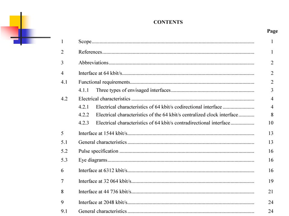
Overview to ITU-T G.703

71
Return to V5

Similar presentations


>")


. HUT Comms Lab., Timo O. Korhonen Topics in PSTN Introduction review of early exchanges PSTN Standards User services.>")


 Given an analog function (voice?) we wish to represent it as a sequence of digital values Pulse Amplitude Modulation.>")


 2. Discuss data communications (15 hrs)>")