Download presentation
Presentation is loading. Please wait.

1
Lights

2
General A non-aeronautical ground light which, by reason of its intensity, configuration or colour, might prevent, or cause confusion in, the clear interpretation of aeronautical ground lights should be extinguished, screened or otherwise modified so as to eliminate such a possibility. In particular, attention should be directed to a non-aeronautical ground light visible from the air within the areas described hereunder: Instrument runway-code number 4: within the areas before the threshold and beyond the end of the runway extending at least m in length from the threshold and runway end and 750 m either side of the extended runway centre line in width. Instrument runway-code number 2 or 3: as in (i), except that the length should be at least m. Instrument runway-code number 1; and non-instrument runway: within the approach area.
, except that the length should be at least m. Instrument runway-code number 1; and non-instrument runway: within the approach area.")
4
Protected zones To protect the safety of aircraft against the hazardous effects of laser emitters, the following protected zones should be established around aerodromes: A laser-beam free flight zone (LFFZ). A laser-beam critical flight zone (LCFZ) A laser-beam sensitive flight zone (LSFZ).
. A laser-beam critical flight zone (LCFZ) A laser-beam sensitive flight zone (LSFZ).")
5
Protected zones

6
Elevated approach lights
Elevated approach lights and their supporting structures shall be frangible except that, in that portion of the approach lighting system beyond 300 m from the threshold: Where the height of a supporting structure exceeds 12 m, the frangibility requirement shall apply to the top 12 m only; and Where a supporting structure is surrounded by non-frangible objects, only that part of the structure that extends above the surrounding objects shall be frangible.

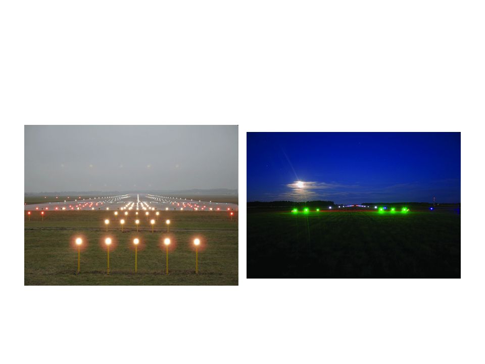
7
Elevated lights Elevated runway, stopway and taxiway lights shall be frangible. Their height shall be sufficiently low to preserve clearance for propellers and for the engine pods of jet aircraft.

8
Surface lights Light fixtures inset in the surface of runways, stopways, taxiways and aprons shall be so designed and fitted as to withstand being run over by the wheels of an aircraft without damage either to the aircraft or to the lights themselves.

9
LIGHT INTENSITY AND CONTROL
The intensity of runway lighting shall be adequate for the minimum conditions of visibility and ambient light in which use of the runway is intended, and compatible with that of the nearest section of the approach lighting system when provided.

10
Aerodrome light intensity settings
Lighting system Number of required intensity settings Intensity setting (%:percentage of required output or cd:effective candelas) (1) (2) (3) 1 2 3 4 5 HIGH INTENSITY LIGHTING SYSTEMS: Precision approach CAT II & III (ALSF-2): - steady burning lamps 0.2% 1% 5% 25% 100% - capacitor discharge lights 450cd 2000cd 20000cd Precision approach CAT I (SSALR): - steady burning lamps Threshold and Wing bar lights Runway edge lights Runway end lights Runway centre line lights Taxiway centre line lights
 (1) (2) (3) HIGH INTENSITY LIGHTING SYSTEMS: Precision approach CAT II & III (ALSF-2): - steady burning lamps. 0.2% 1% 5% 25% 100% - capacitor discharge lights. 450cd. 2000cd cd. Precision approach CAT I (SSALR): - steady burning lamps. Threshold and Wing bar lights. Runway edge lights. Runway end lights. Runway centre line lights. Taxiway centre line lights.")
11
Lighting system Number of required intensity settings Intensity setting (%:percentage of required output or cd:effective candelas) (1) (2) (3) 1 2 3 MEDIUM INTENSITY LIGHTING SYSTEMS Precision approach CAT I (MALSR): - steady burning lamps 4% 20% 100% - capacitor discharge lights 450cd 2000cd 20000cd Simple approach light system (ODALS) 300cd 1500cd 5000cd Threshold lights 10% 30% Runway edge lights Runway end lights
 (2) (3) MEDIUM INTENSITY LIGHTING SYSTEMS. Precision approach CAT I (MALSR): - steady burning lamps. 4% 20% 100% - capacitor discharge lights. 450cd. 2000cd cd. Simple approach light system (ODALS) 300cd. 1500cd. 5000cd. Threshold lights. 10% 30% Runway edge lights. Runway end lights.")
12
Emergency Lighting At an aerodrome provided with runway lighting and without a secondary power supply, sufficient emergency lights should be conveniently available for installation on at least the primary runway in the event of failure of the normal lighting system. When installed on a runway the emergency lights should, as a minimum, conform to the configuration required for a non-instrument runway.

13
Aerodrome Beacon An aerodrome beacon shall be provided at each aerodrome intended for use at night, except when, in special circumstances, the beacon is considered by the Certifying Authority as unnecessary upon determination that it is not required by one or more of the following conditions: the aerodrome is located on or near a frequently used night VFR route. the aerodrome is frequently used by aircraft navigating visually during periods of reduced visibility. it is difficult to locate the aerodrome from the air due to surrounding lights or terrain. The aerodrome beacon shall be located on or adjacent to the aerodrome in an area of low ambient background lighting.
![]()
14
Approach lighting system
The approach lighting system differs according to runway: Non-instrument runway Non precision approach runway Precision approach runway categoryI Precision approach runway categoryII and III

15
Example of approach and runway lighting
for runway with displaced thresholds

16
Precision Approach CategoryI Lighting System

17
Visual Approach Slope Indicator Systems
A visual approach slope indicator system shall be provided to serve the approach to a runway where one or more of the following conditions exits: The runway is not served by an electronic glide path and the runway is used by turbojet or other aircraft with similar approach guidance requirements; The pilot of any type of aircraft may have difficulty in judging the approach due to: Inadequate visual guidance such as is experienced during an approach over water or featureless terrain by day or in the absence of sufficient extraneous lights in the approach area by night, or Misleading information such as is produced by deceptive surrounding terrain or runway slopes;

18
Visual Approach Slope Indicator Systems
The presence of objects in the approach area may involve serious hazard if an aircraft descends below the normal approach path, particularly if there are no non-visual or other visual aids to give warning of such objects; Physical conditions at either end of the runway present a serious hazard in the event of an aircraft under shooting or overrunning the runway; and Terrain or prevalent meteorological conditions are such that the aircraft may be subjected to unusual turbulence during approach.

19
Visual Approach Slope Indicator Systems
The standard visual approach slope indicator systems shall consist of PAPI and APAPI systems conforming to the specifications. PAPI or APAPI shall be provided when one or more of the conditions specified in manual exist in accordance with the following: PAPI shall be installed where the code number is 3 or 4. PAPI or APAPI shall be installed where the code number is 1 or 2.

20
PAPI The PAPI system shall consist of a wing bar of 4sharp transition multi-lamp (or paired single lamp) units equally spaced. The system shall be located on the left side of the runway unless it is physically impracticable to do so.
 units equally spaced. The system shall be located on the left side of the runway unless it is physically impracticable to do so.")
21
PAPI Sitting and Angle of Elevation Settings

22
APAPI The APAPI system shall consist of a wing bar of 2sharp transition multi-lamp (or paired single lamp) units. The system shall be located on the left side of the runway unless it is physically impracticable to do so.

23
APAPI Sitting and Angle of Elevation Settings

24
Obstacle Protection Surface for Visual Approach Slope Indicator Systems

25
Aerodrome Flight Manoeuvring Area Hazard Lights
The dimensions of the flight manoeuvring area shall permit the critical aircraft arriving and departing the airport to manoeuvre safely in both the all engine operating or one engine out configuration. The obstacle free area shall be determined by drawing arcs of a radius of 2 .3NM centred on each runway threshold and joining those arcs with tangent lines and shall provide a minimum of 100m vertical obstacle clearance.

26
Flight Manoeuvring Area

27
Runway Lead-In Lighting Systems
A runway lead-in lighting system should be provided where it is desired to provide visual guidance along a specific approach path, for reasons such as avoiding hazardous terrain or for purposes of noise abatement. Each group of lights of a runway lead-in lighting system should consist of at least three flashing lights in a linear or cluster configuration. The system may be augmented by steady burning lights where such lights would assist in identifying the system.

28
Runway Identification Lights (RILS)
Runway identification lights should be provided: at the threshold of a non-precision approach runway where it is not practical to provide other visual approach aids; or where extraneous non-aeronautical lights or lack of daytime contrast detract from the effectiveness of approach lights or where the threshold is difficult to identify and enhanced conspicuity is necessary; and where a runway threshold is permanently displaced from the runway extremity or temporarily displaced from the normal position and additional threshold conspicuity is necessary.

29
Runway Edge Lights Low intensity runway edge lights shall be provided for a runway intended for use at night where the code number is 1 or 2. Medium intensity runway edge lights shall be provided for a runway intended for use at night where the code number is 3 or 4. High intensity runway edge lights should be provided on a runway intended for take-off with an operating minimum below an RVR of the order of 2600ft (800m) by day.
 by day.")
30
Runway Edge Light Mounting Height

31
Runway Threshold Lights
Runway threshold lights shall be provided for a runway equipped with runway edge lights except on a non-instrument or non-precision approach runway where the threshold is displaced and wing bar lights are provided. The runway threshold lights described in, shall be placed in two groups symmetrically disposed about the runway centre line with the outermost runway threshold lights positioned to align with the runway edge lights and the remainder spaced at intervals of 3m.

32
Wing Bar Lights Wing bar lights shall be provided on a runway where the threshold is displaced to indicate the location of the displaced threshold. Wing bar lights shall consist of two groups of lights (ie. wing bars) each consisting of; three lights when used to mark the location of a displaced threshold for a runway 30m or less in width; four lights when used to mark the location of a displaced threshold for a runway greater than 30m in width but not greater than 45m in width; five lights when used to mark the location of a displaced threshold for a runway greater than 45m in width; and seven or eight lights when provided on a precision approach runway categoryII or III.
 each consisting of; three lights when used to mark the location of a displaced threshold for a runway 30m or less in width; four lights when used to mark the location of a displaced threshold for a runway greater than 30m in width but not greater than 45m in width; five lights when used to mark the location of a displaced threshold for a runway greater than 45m in width; and. seven or eight lights when provided on a precision approach runway categoryII or III.")
33
Examples of Threshold and Wing Bar Lights

34
Runway End Lights Runway end lights shall be provided for a runway equipped with runway edge lights. Runway end lights on a runway less than 45m in width shall consist of six lights arranged in two groups, and on a runway 45m and greater in width, eight lights arranged in two groups. Runway end light mountings shall be frangible.

35
Runway Centre Line Lights
Runway centre line lights shall be provided on a precision approach runway categoryII or III. Runway centre line lights shall be fixed lights showing variable white from the threshold to the point 900m from the runway end; alternate red and variable white from 900m to 300m from the runway end; and red from 300m to the runway end.

36
Runway Touchdown Zone Lights
Touchdown zone lights shall extend from the threshold for a longitudinal distance of 900m, except that, on runways less than 1800m in length, the system shall be shortened so that it does not extend beyond the midpoint of the runway. Touchdown zone lights shall be fixed unidirectional lights showing variable white.

37
Stopway Lights Stopway lights shall be provided for a stopway intended for use at night. Stopway lights shall be fixed unidirectional lights showing red in the direction of the runway. Stopway light mountings shall be frangible.

38
Taxiway Centre Line Lights
Taxiway centre line lights shall be provided on a runway forming part of a standard taxi-route and intended for taxiing in runway visual range conditions less than a value of the order of 1400ft (400m) except that these lights need not be provided where there is a low volume of traffic and taxiway edge lights and centre line marking provide adequate guidance.
 except that these lights need not be provided where there is a low volume of traffic and taxiway edge lights and centre line marking provide adequate guidance.")
39
Taxiway Lighting

40
Taxiway Intersection Lights
Taxiway intersection lights should be provided at a taxiway intersection where it is desirable to define a specific aeroplane holding limit and there is no need for stop-and-go signals as provided by a stop bar. Taxiway intersection lighting shall consist of at least three fixed unidirectional lights showing yellow in the direction of approach to the intersection with a light distribution similar to taxiway centre line lights if provided. The lights shall be disposed symmetrically about, and at 90° to, the taxiway centre line, with individual lights spaced 1.5m apart.

41
Apron Floodlighting Apron floodlighting should be provided on an apron, and on a designated isolated aircraft parking position, intended to be used at night. The spectral distribution of apron floodlights shall be such that the colours used for aircraft marking connected with routine servicing, and/or surface and obstacle marking, can be correctly identified.

42
Aircraft Stand Manoeuvring Guidance Lights
Aircraft stand manoeuvring guidance lights should be provided to facilitate the positioning of an aircraft on an aircraft stand intended for use in poor visibility conditions unless adequate guidance is provided by other means. The lights indicating a stop position shall be fixed, unidirectional lights, showing red.

43
Road-Holding Position Light
A road-holding position light shall be provided at each road-holding position serving a runway when it is intended that the runway will be used in runway visual range conditions less than a value of the order of 1400ft (400m). The road-holding position light shall comprise: a controllable red (stop)/green (go) traffic light; or a flashing red light.
. The road-holding position light shall comprise: a controllable red (stop)/green (go) traffic light; or. a flashing red light.")
Similar presentations


 Left turn to Taxi A>")


