Download presentation
Presentation is loading. Please wait.

1
ASKAP status and commissioning Astronomy and Space Science Max Voronkov | ASKAP Software scientist Kiama - 3 March 2014 Some pictures from Ben Humphreys, John Bunton, Aidan Hotan, Dave McConnel and Tom Cox

2
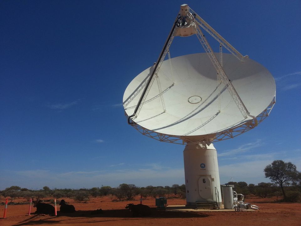
Australian Square Kilometre Array Pathfinder Radio interferometer with 36 identical 12m antennas Located in a radio-quiet zone in Western Australian outback Key new features: Phased array feed Multiple synthetic beams on the sky 3-axis mount Wide field of view

3
Phased Array Feed (PAF) 188 independent receivers Beamformer computes 36 linear combinations making individual beams on the sky 3-axis mount gives a better stability of the system and simplifies imaging
 188 independent receivers Beamformer computes 36 linear combinations making individual beams on the sky 3-axis mount gives a better stability of the system and simplifies imaging")
4
BETA: first 6 antennas of ASKAP, MkI PAF BETA Beamformer supports 9 beams only First tests were done with two 3-antenna arrays

5
Current status: BETA and Beyond Most commissioning efforts goes towards BETA Most development is towards ADE (2 nd generation h/w) cheaper PAF with better Tsys across the frequency range less electronics in the antenna pedestals simpler and more maintainable design in many cases Number of milestones of general importance Remote observations from Sydney Pawsey centre supercomputer is ready Ben’s talk – for HPC matters Aidan’s talk – for info on beamforming
 cheaper PAF with better Tsys across the frequency range less electronics in the antenna pedestals simpler and more maintainable design in many cases Number of milestones of general importance Remote observations from Sydney Pawsey centre supercomputer is ready Ben’s talk – for HPC matters Aidan’s talk – for info on beamforming")
6
The Pawsey High Performance Computing Centre for SKA Science AUD$80M super-computing centre Supports storage and processing of data from the Australian SKA Pathfinder and the Murchison Widefield Array Construction completed April 2013

7
BETA Hardware DRx can delay stream up to about 5 microsec Beamformers have an integrator after the fine filter bank (FFB) H/W fringe rotator is part of the beamformer Initial setup was two 3- antenna arrays Antenna 1-3-6 sub- array is compact enough, so it can be used without fringe rotator
 H/W fringe rotator is part of the beamformer Initial setup was two 3- antenna arrays Antenna sub- array is compact enough, so it can be used without fringe rotator")
8
Early work with the Software correlator 16 MHz bandwidth, 1:10 duty cycle and up to 4 beams, 3 antennas 3-beams (made on Virgo) arranged in a line, 928 MHz, 13h track 1549-790 (pointing centre, boresight beam), 1610-771 (centre of the most offset beam) + two weaker sources Delay tracking via DRx Phase tracking in software Can’t synchronise with DRx Calibration on 1934-638 Each beam separately Image beams separately Linear mosaicing With an idealised beam model Good data reduction exercise
 arranged in a line, 928 MHz, 13h track (pointing centre, boresight beam), (centre of the most offset beam) + two weaker sources Delay tracking via DRx Phase tracking in software Can’t synchronise with DRx Calibration on Each beam separately Image beams separately Linear mosaicing With an idealised beam model Good data reduction exercise")
10
Many months of artefact chasing The biggest issue was tracked down to the idiosyncrasies of the DDR memory controllers on DSP card Also note the ripple in this spectrum (filter response). It can be (and is now) corrected in the software
 corrected in the software.")
11
Delay tracking controlled by ingest pipeline Can synchronise delay and phase tracking and flag invalid samples Simplifies debugging Full control over DRx, H/W fringe rotator and software corrections

12
Getting HW fringe rotator to work

13
Phase is free-wheeling, timing is painful Timing becomes crucial, software needs to understand what the hardware is doing Parameters are loaded on an event but applied when the current 55.296ms block of data ends, correlator knows nothing about it Tried to operate with 90x55.296ms and 91x55.296ms cycles instead of 5s Got beating with 1pps interrupts Large phase jumps when we update phase rate parameter Significant mis-timing

14
Investigate timing astronomically Track geometric delay/phases via DRx + software for a strong source Set different phase rates and measure what phase we get Slope corresponds to 14.5±0.4s delay 3 correlator cycles?

15
Timing – can only account for 2 cycles

16
Imaging with two 3-antenna sub-arrays Full 304 MHz bandwidth 9 beams, stokes I Beams made using the Sun Didn’t survive power cycle (most likely due to attenuators) Calibration on 1934-638 Separately for each beam Also considering a hybrid approach where the calibration per beam is done once per day and routine calibration is antenna-based No isolated calibrators Delay tracking per antenna w-projection fixes differential delay across the field well Correlator has been repatched into the final 6-antenna configuration two weeks ago
 Calibration on Separately for each beam Also considering a hybrid approach where the calibration per beam is done once per day and routine calibration is antenna-based No isolated calibrators Delay tracking per antenna w-projection fixes differential delay across the field well Correlator has been repatched into the final 6-antenna configuration two weeks ago")
17
First (serious) look at bandpasses Frequency-dependent structure of beamformer weights needs a more careful look Wavy pattern is because of confusing sources! Bandpass has been calibrated on another 1934- 638 scan taken a few hours earlier

18
Summary BETA is coming along - extremely valuable engineering experience All but one bug found with BETA also relevant for ADE/ASKAP - saved time Exercise full system, including software. Learn beamforming and refine calibration model Timing across boundary of different systems Source of frustration Avoid free-wheeling behaviour? The presence of beamformer as a separate hardware makes synchronisation difficult. Avoid multiple clock domains? Do as much in the software as possible?

19
Astronomy and Space Science Thank you Astronomy and Space Science Max Voronkov ASKAP Software Scientist t +61 2 9372 4427 e maxim.voronkov@csiro.au w www.narrabri.atnf.csiro.au/people/vor010 We acknowledge the Wajarri Yamatji people as the traditional owners of the Observatory site

Similar presentations


![ASKAP Status Update CSIRO ASTRONOMY AND SPACE SCIENCE David Brodrick EPICS [Spring] Collaboration Meeting 22nd October 2014.](/13/4072011/big_thumb.jpg "ASKAP Status Update CSIRO ASTRONOMY AND SPACE SCIENCE David Brodrick EPICS [Spring] Collaboration Meeting 22nd October 2014.>")


: Focal Plane Arrays Case study: WSRT System overview Receiver and.>")

 Project SKA Meeting - April 2006 Anne Green.>")


