Download presentation
Presentation is loading. Please wait.

1
TE-MSC

2
07/04/2016 Jose Ferradas TE-MSC-MDT Alejandro Carlon TE-MSC-MDT Juan Carlos Perez TE-MSC-MDT On behalf to MSC-MDT section and Coil working group

3
Overview CERN Lab 927 Equipment Nominal models used CERN MQXFS Measurements procedure What’s next? Conclusions

5
1. OVERVIEW Measurements at one single stage: A fter impregnation Currently CERN approach: Short coils Long coils Currently FNAL, BNL & LBNL approach: Short coils Long coils Mechanical measurements using CMM Portable Device (FARO Arm) Mechanical measurements using CMM machine Tests with CMM machine Tests with CMM Portable Device (FARO arm) Work in progress
 Mechanical measurements using CMM machine Tests with CMM machine Tests with CMM Portable Device (FARO arm) Work in progress.")
6
1. OVERVIEW What happens if we compare Faro Arm measurements to CMM measurements? CMM agreement difference between CERN Faro Arm and BNL Faro Arm See presentation from E.Holik – FNAL The aim of this presentation is to explain the procedure followed at Lab.927 CERN First draft delivered

7
1. OVERVIEW Note that: No topics different than the procedure itself will be addressed Important topics were moved to next meeting Procedure sets the actions and their order independently of reference used, software used…

9
2.EQUIPMENT CMM Portable device: Faro Arm Edge 2.7 3 mm. Touch Probe Faro Arm Edge 2.7 volumetric maximum deviation: 41μm Faro Arm Edge 2.7 repeatability: 29 μm Periodically sent to calibration Polyworks Inspection Software 2015

10
2.EQUIPMENT Dedicated area for metrology inside the workshop Marble for measurements (2.5 m x 1.5 m) Arm fixed to the table using rigid support
 Arm fixed to the table using rigid support")
11
2.EQUIPMENT MQXFS coils clamped using a specially designed support Inner cylinder placed at 255 mm height Possible to probe inner diameter Support parts are aligned and screwed before operations Support fixed to the table using conventional clamps

13
3. MODELS Analysis done by CAD comparison: Measured values compared with nominal ones (extracted from the CAD model). Two different CAD models used: 1.Simplified CAD model for analysis Solid block Only external shape considered 2.Simplified CAD model for cross section alignment Surface Outer cylinder and keyway * Note that necessity of one model for alignment is due to the software used. If the software is different it might not be necessary to use it
. Two different CAD models used: 1.Simplified CAD model for analysis Solid block Only external shape considered 2.Simplified CAD model for cross section alignment Surface Outer cylinder and keyway * Note that necessity of one model for alignment is due to the software used. If the software is different it might not be necessary to use it.")
15
5.PROCEDURE Metrology inspection performed as following: Coil clamping Data acquisition Analysis Coil clamping Data acquisition Analysis

16
5.PROCEDURE Distance between supports : 90 cm Distance between each end and support : 30 cm Objective: Avoid any possible movement Gravity working against banana shape deformation

17
5.PROCEDURE Once the coil is correctly clamped: Marble should be cleaned removing any possible disturbing object or tooling Area should be delimited, restricting the access to other person different to operator Data acquisition procedure: 1.Device calibration 2.Device validation 3.Pre-alignment 4.General geometry probing 5.Best-fit alignment 6.Cross section probing

18
5.PROCEDURE Device calibration Device validation Pre- alignment General geometry probing Alignment improving Cross section probing

19
5.PROCEDURE Performed following FARO hardware calibration procedures: Hole compensation : Probe calibration Single point articulation test (SPAT): Arm calibration (Repeatability) In case of failing, error message will be displayed
: Arm calibration (Repeatability) In case of failing, error message will be displayed")
20
5.PROCEDURE Measurements over calibrated pieces In order to assess good performance of the device

21
5.PROCEDURE Usual results: Hole compensation 2-sigma: Below 11μm Calibrated pieces: Below 8μm

22
5.PROCEDURE Starting point: Pre-alignment of real coil to CAD model Using 6 “Surface point alignment” 6 points are defined in the CAD model, operator must probe the same 6 points in real coil For improving reproducibility, singular points are chosen (Corners, edges…)
")
23
5.PROCEDURE Once pre-alignment is done, data is collected over: Lead end plane Return end plane Outer cylinder Inner cylinder Left Mid-plane Right Mid-plane Left key plane Right key plane Bottom key plane Necessary to be as perpendicular as possible while probing

24
5.PROCEDURE After first part of the probing process, information is enough to perform a better alignment Best-fit alignment of real point cloud to CAD model is performed using: Lead end plane Outer cylinder Left key plane Right key plane All degrees of freedom are fixed Coil is aligned to Lead end in order to define the cross section distances

25
5.PROCEDURE With the new alignment, software will locate all the cross section. Cross sections are defined in the CAD model using the following scheme: Cross sections are probed: Projection method – 5 mm. Trying to be as perpendicular as possible with the probe

26
5.PROCEDURE Analysis procedure is done as follows (Software requirement): Normal vectors extraction Each CS is aligned individually to OD and Keyway (Modified CAD) Aligned point cloud is exported as.TXT.TXT point cloud is imported as separate data Results extracted comparing imported data to full CAD
: Normal vectors extraction Each CS is aligned individually to OD and Keyway (Modified CAD) Aligned point cloud is exported as.TXT.TXT point cloud is imported as separate data Results extracted comparing imported data to full CAD")
27
5.PROCEDURE Example of cross section alignment

28
5.PROCEDURE Original CS Banana shape present CS aligned using special CAD Resulting CS Aligned points compared with full CAD

29
5.PROCEDURE General geometry results Banana shape Coil length Mid-planes angle Keyway width … Inner radius Outer radius Cross section results Individual features defined in each cross section Mid-plane excess Inner / outer radius Keyway information

31
6. NEXT Very important topics have been removed from the scope of this presentation These topics will be addressed in next meeting: Reference for measurements: Discussion & standardization Reference influence over results Differences between CERN side and non-CERN side Results extraction analysis: Differences over results extraction / Choosing right method Coil fiducialization CERN Faro arm VS CERN CMM machine study Results for coils to be presented

34
CMM FARO Arm Comparison study between: Results obtained in different relative positions Coil – Device Those obtained at CERN main metrology service Initial results show good agreement on deviation vector map.

35
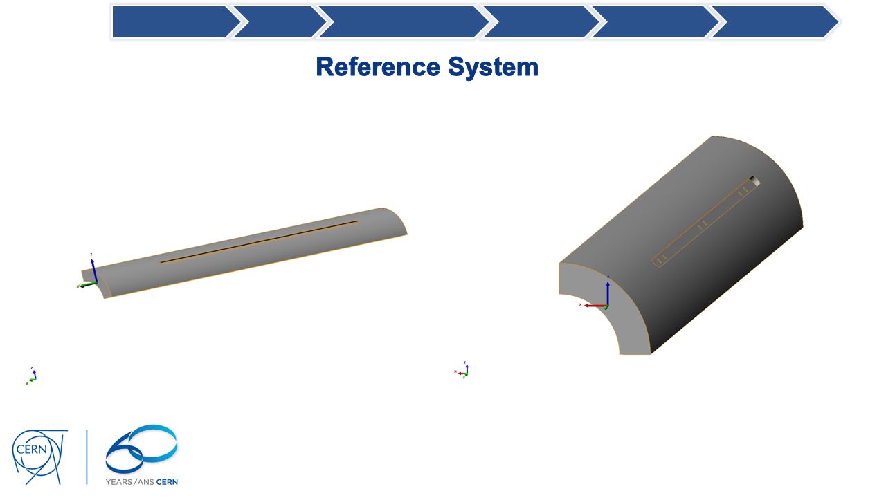
Polyworks Inspection approach: Reference system defined using nominal features (CAD) Origin is set in Lead End Plane. X & Z axis are perpendicular to each mid-plane. Y axis going in longitudinal direction This means, the coordinate system is attached to the CAD. It is not defined during measurements. It is not a metrological reference. It is impossible to completely define the reference by measuring features. To be able to use it, the CAD is best-fitted to our real measured geometry Therefore, reference system relies on the good alignment with the real piece

37
Polyworks Inspection approach: For MQXFS coils: First: All features of the coil are defined by probing Then, the alignment to the CAD model is performed: Longitudinal translation fixed by best-fitting measured lead plane to nominal lead end plane. Lead end measured plane is made coincident with the nominal plane from CAD (First degree of freedom) Second translation fixed by best-fitting to outer cylinder (Second degree of freedom) Rotation fixed by best-fitting to key planes (Third degree of freedom) Final alignment is the global result minimising the deviation between all features used for it. It is an average position trying to get minimum deviation. Once both entities are aligned. Each cross section is measured by probing.
 Second translation fixed by best-fitting to outer cylinder (Second degree of freedom) Rotation fixed by best-fitting to key planes (Third degree of freedom) Final alignment is the global result minimising the deviation between all features used for it. It is an average position trying to get minimum deviation. Once both entities are aligned. Each cross section is measured by probing..")
38
Polyworks Inspection approach: INCONVENIENTS: Reference system relies on the good fit of our real coil to the nominal model If the features used for the alignment are out of tolerance, the alignment could be not good Small alignment deviations in the first part of the coil become bigger with length ADVANTAJES: Time to carry out the measurements is decreased. It is possible to perform the inspection following a stablished inspection guide. Everything is previously defined before starting the measurements. Operator should only probe the stablished points, decreasing probability of additional errors (coils are always measured in the same way). For cross sections, points are projected by the software within a stablished distance of +/- X mm. This fact allows us to not discard this approach. Results in deviation vector map from CMM show good agreement with our measurements (See previous or next slides)
. For cross sections, points are projected by the software within a stablished distance of +/- X mm. This fact allows us to not discard this approach. Results in deviation vector map from CMM show good agreement with our measurements (See previous or next slides).")
39
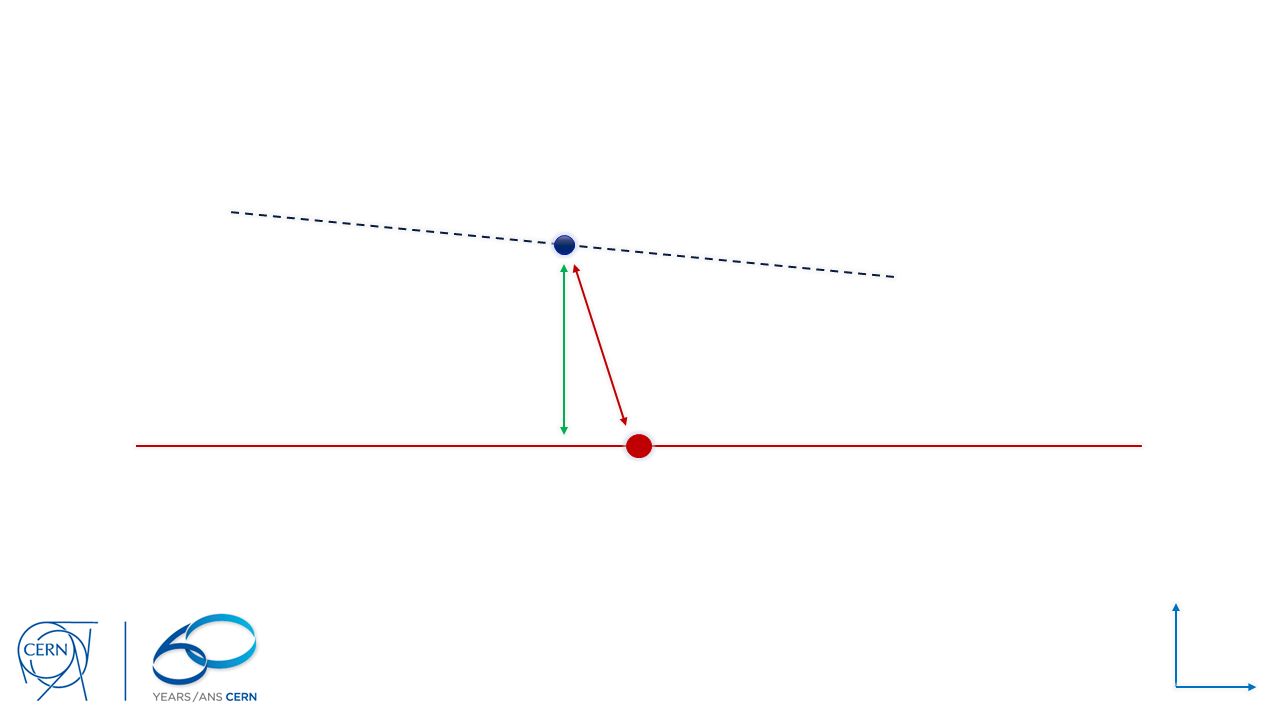
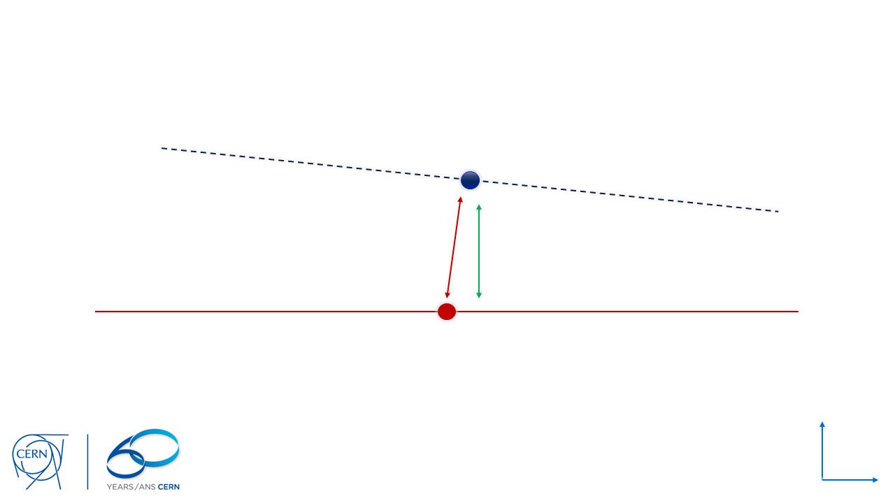
Polyworks Inspection approach: NOTE THAT: Errors on reference system will influence the cross section points acquisition. The possible error in alignment is influencing us when the cross sections are measured. But similar effect is also present in the projection performed by the software. However, the analysis of each cross section is done by treating the points of each cross section and best-fitting them individually to the nominal curve. This is, the alignment used for the final analysis is different (Local).
..")
40
Nominal Measured

41
Correct CS Nominal CS Measured CS Projection Zone

Similar presentations


 with a mechanical focus.Objective: Given the Applying GD&T StAIR.>")


. NFS Engineering Research Center for Reconfigurable Manufacturing Systems College of engineering, University of.>")

>")

