Download presentation
Presentation is loading. Please wait.

1
TPC R3 B R3B – TPC Philippe Legou Krakow, February 2010 2nd
CEA Saclay - France B TPC R3 © Ph. LEGOU & F.G. NIZERY

2
2- Principle of detection 3- Construction of the detector:
Outline 1- Motivation 2- Principle of detection 3- Construction of the detector: - the detector - the front-end electronics 4- Results

3
R3B - TPC in few words … . What is it?
R3B for : Reaction studies with Radioactive Relativistic Beams) What is it? ▪ a multi track Time Projection Chamber detector for protons to beam heavy ions. Why ? to measure precisely kinematics characteristics of particles with minimum amount of material in the beam. Who ? (for instance) several teams of CEA Saclay : SPhN, SIS, SEDI Cracovie (university and Nuclear Physics institute) IN2P3 CNRS CPPM Bratislava (Nuclear Physics Institute) Where ? at GSI, just after GLAD magnet. When ? end of 2015 ?
 What is it ▪ a multi track Time Projection Chamber detector for. protons to beam heavy ions. Why to measure precisely kinematics characteristics of. particles with minimum amount of material in the beam. Who (for instance) several teams of CEA Saclay : SPhN, SIS, SEDI. Cracovie (university and Nuclear Physics institute) IN2P3 CNRS CPPM. Bratislava (Nuclear Physics Institute) Where at GSI, just after GLAD magnet. When end of 2015")
4
R3B hall in the FAIR facility
Still to build FAIR GSI Cave C R3B

5
the Mesh Micromegas : MICROMEsh GASeous
Close-up of a mesh On behalf of Rui de Oliveira at CERN the Mesh Two way of making a mesh for a Micromegas design A Kapton foil streched and glued on a Frame, and the frame is screwed on the PCB A « bulk » which can be seen as Other layers of the PCB Improvements are possible (other gap) Ready to use solution Mounting operation is required No improvements + difficult to repair
 Ready to use solution. Mounting operation is required. No improvements + difficult to repair.")
6
Micromegas used in TPC mode
Micromegas : MICROMEsh GAS detector TPC: Time Projection Chamber Cathode Gas Ionization electrons Electrical field Mesh 100 µm Spacers Mother board with strips Beam

7
Bulk Micromegas ▪ Large area and robustness
▪ Easy implementation ▪Low cost ▪Industrial process Bulk Micromegas obtained by lamination of a woven grid on an anode with a photo-imageable film « Bulk » : construction process Low material detectors

8
Choice of the amplification gap
electron Ion tail Small gap fast signals 12.5 m Micromegas has been tested for NA48-3 Ion collection time are <5 ns No Ballistic deficit

9
a 100 µm mesh bulk detector No frame anymore ! Mesh 10×10 cm2
100mm kapton +5mm Cu

10
R3B – TPC test setup in cave C October 2008 & March 2009
Six detectors along the beam between scintillators for the DACQ trigger Beam direction

11
+ + a TracKer 48 channels Mother board Width of strips : 835 µm
Very fast Preamp Space between 2 strips : 65 µm Or 7 channels of 5mm with 150 µm between 2 strips.
![]()
12
Front-end module : FAMMAS (ph.Legou)
( Fast Amplifier Module for Micromegas ApplicationS) In few figures … Power supply : + 5V -5V Consumption 50 mW Input: positive or negative Size: 22 x 20 x 5 mm weight : 4g Noise: 600 µV rms Rise time : < 1ns
 In few figures … Power supply : + 5V -5V. Consumption 50 mW. Input: positive or negative. Size: 22 x 20 x 5 mm. weight : 4g. Noise: 600 µV rms. Rise time : < 1ns.")
13
Characterization of the front-end in the lab
Very good uniformity of the noise on the 48 channels front-end cards on each tracker detector

14
CEA - FAMMAS Front-end module
FAMMAS vs commercial Module Minicircuits 1GHz ZFL-1000LN CEA - FAMMAS Front-end module Amplitude width Amplitude width 3.07ns F4 F2 F4 2.57ns F2 Fall time 90% - 10% Rise time 10% - 90% Fall time 90% - 10% Rise time 10% - 90% 2.16ns F1 F1 1.11ns 1.08ns F6 0.8ns F6

15
Characterization of the detector
Both detectors have the same gain in the area of the operating point.

16
Test on a 100 µm gap detector at CERN
Test conditions : visualisation at about 30 meters coaxial cable. Gaz : COMPASS. Beam. Mesh Voltage : 350 V Mesh Voltage : 370 V

17
Test on a 100 µm gap detector at CERN
No crosstalk between neighbour channels Test conditions : visualisation at about 30 meters coaxial cable. Gaz : COMPASS. Beam. Mesh Voltage : 340 V Mesh Voltage : 340 V

18
Tests on a 100 µm gap Bulk detector at GSI
… 2008, october 19th. Test conditions : visualisation at about 30 meters coaxial cable. Gaz : P10 Beam. Mesh Voltage : 380 V Drift Voltage : 2000V

19
Resistive micromegas detectors
By adding a resistive foil (2MΩ/□ ) on the strips we can spread the charge on several strips. M. Dixit et al. (Carleton U. – Ottawa) Micromegas mesh Resistive foil Glue Pads
 on the strips we can spread the charge on several strips. M. Dixit et al. (Carleton U. – Ottawa) Micromegas mesh. Resistive foil. Glue. Pads.")
20
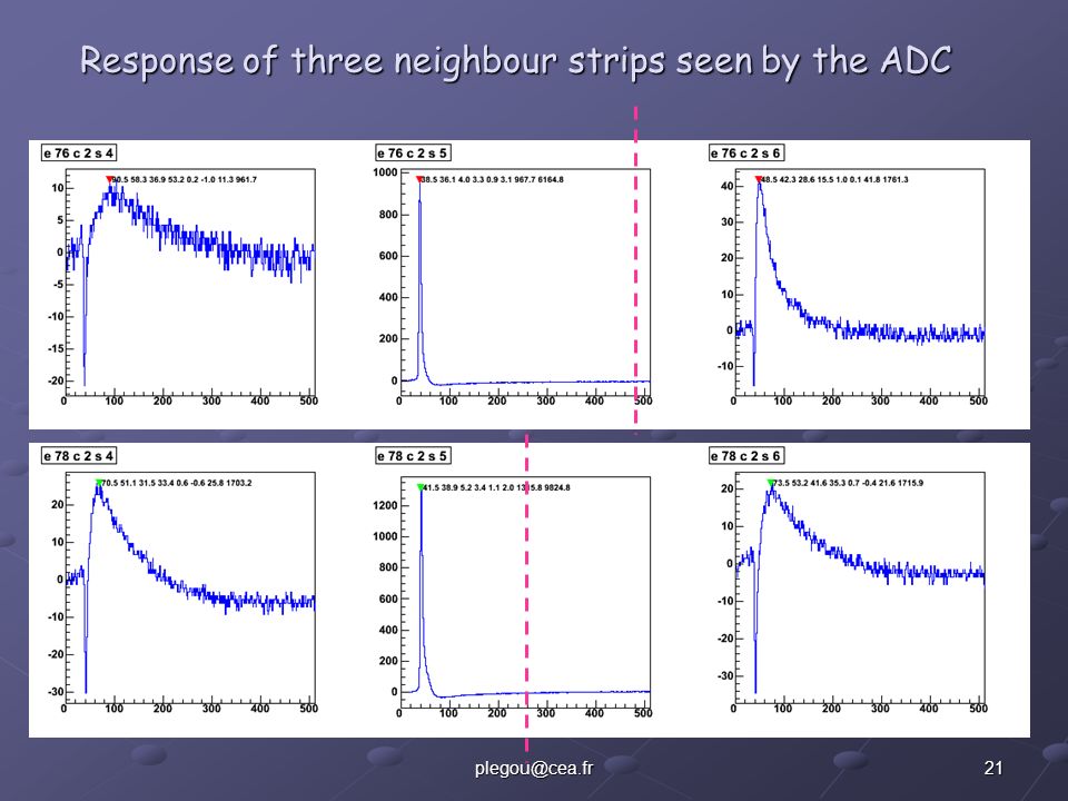
Signals on resistive Bulk detectors Pics from the scope of two
neigbourg strips

21
Response of three neighbour strips seen by the ADC
22
Tests on a resistive 100 µm gap Bulk detector at GSI
March 2009 in Cave C. Classical detectors The charge is more spread on resistive detectors « classic 835 µ » « resistive 835 µ » « resistive 5 mm »

23
The « One meter » detector test - station
One meter station @ saclay in « lab #534 » The elctrical field cage Electric field cage To provide an uniform fieldIn the whole convertion gap ≈2m Aim of this detector : to test the real drift distance

24
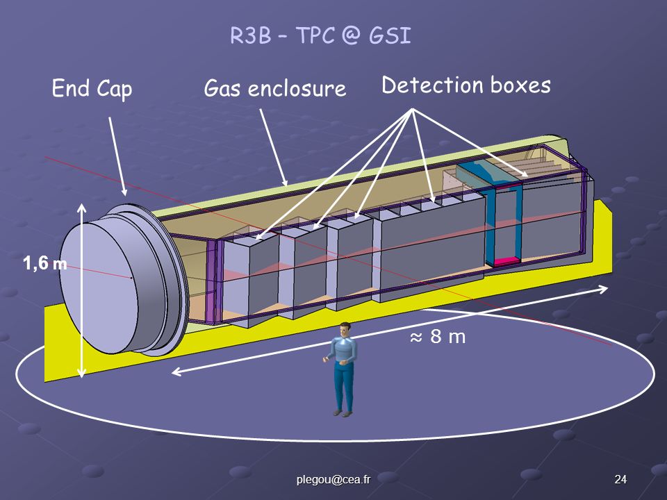
R3B – TPC @ GSI End Cap Gas enclosure Detection boxes 1,6 m ≈ 8 m
25
R3B TPC … the just after GALD magnet and the Helium tank… .
GLAD magnet ≈4 m

26
Tracks seen by all the chambers
C 835 µm C 835 µm R 835 µm R 5 mm R 5 mm C 835 µm

27
Pads response function of the pads
classical 835 µm resistive 835 µm resistive 5 mm

28
- the transfert properties of the magnet.
Taking into account : - the transfert properties of the magnet. - the multiple scattering from the target point to the detector. We need a position reconstruction in the TPC of 200 µm RMS

Similar presentations

 : a multi-stage device using micromeshes for tracking particles MPGD’s Workshop at NIKHEF April 16th2008 April 16th.>")


>")


>")


