Download presentation
Presentation is loading. Please wait.

1
ITEC 275 Computer Networks – Switching, Routing, and WANs Week 7 Robert D’Andrea

2
Agenda Learning Activities – Domain Name Server (DNS) – Summarization – Root Owner DNS – Routing tables – Spanning Tree Protocol – Rapid Spanning Tree Protocol – Static versus Dynamic Routing – Routing Protocols and Characteristics
 – Summarization – Root Owner DNS – Routing tables – Spanning Tree Protocol – Rapid Spanning Tree Protocol – Static versus Dynamic Routing – Routing Protocols and Characteristics")
3
DNS Domain Names

4
Interpreting a DNS domain names DNS has a method of noting and interpreting the fully qualified path to a DNS domain name similar to the way full paths to files or directories are noted or displayed at a command prompt. For example, a directory tree path helps point to the exact location of a file stored on your computer. For Windows computers, the back slash (\) indicates each new directory that leads to the exact location of a file. For DNS, the equivalent is a period (.) indicating each new domain level used in a name.
 indicates each new directory that leads to the exact location of a file. For DNS, the equivalent is a period (.) indicating each new domain level used in a name..")
5
Interpreting File Names UNIX uses the concept of relative and absolute file names. If a file name is preceded by a forward slash (e.g. /bin), the name is absolute. If the name is without a leading slash, it is considered relative to your current working directory. Example1: Present location is /abc/xyz, I am want to remove /abc/xyz/read/hello.txt file. Using relative path: rm read/hello.txt
, the name is absolute. If the name is without a leading slash, it is considered relative to your current working directory. Example1: Present location is /abc/xyz, I am want to remove /abc/xyz/read/hello.txt file. Using relative path: rm read/hello.txt.")
6
Interpreting a DNS domain names For DNS, an example of a domain name with multiple levels is the following, a fully qualified domain name (FQDN): host-a.example.microsoft.com. Unlike the file name example, a DNS FQDN, when read from left to right (/proc/bus/usb), moves from its most specific information (the DNS name for a computer called "host-a") to its highest or most general piece of information (the trailing period (.) that indicates the root of the DNS name tree). This example shows the four separate DNS domain levels that lead away from the specific host location of "host-a":
, moves from its most specific information (the DNS name for a computer called host-a ) to its highest or most general piece of information (the trailing period (.) that indicates the root of the DNS name tree). This example shows the four separate DNS domain levels that lead away from the specific host location of host-a :.")
7
Interpreting a DNS domain names 1. The "example" domain, which corresponds to a subdomain where the computer name "host-a" is registered for use. 2. The "microsoft" domain, which corresponds to the parent domain that roots the "example" subdomain. 3. The "com" domain, which corresponds to the top-level domain designated for use by business or commercial organizations that roots the "microsoft" domain. 4. The trailing period (.), which is a standard separator character used to qualify the full DNS domain name to the root level of the DNS namespace tree.
, which is a standard separator character used to qualify the full DNS domain name to the root level of the DNS namespace tree..")
8
Root Servers When a computer on the Internet needs to resolve a domain name, it uses resolver software to do the lookup. A resolver breaks the name up into its labels from right to left. The first component is queried using a root server to obtain the responsible authoritative server. Queries for each name are performed until a name server returns the answer of the original query.

9
Interpreting a DNS domain names As of 2013, there are 13 root name servers, with names in the form letter.root-server.net. This does not mean that there are only 13 physical servers; each site uses redundant computer equipment to provide reliable service in when hardware and software fail on occasion.

10
Route Summarization

11
Classful Boundary Summarization

12
Routing Tables

13
Dual Stack and Tunneling IPv4/IPv6

14
Bridge Protocol Data Unit (BPDU) What are BPDUs? BPDUs are data messages that are exchanged across the switches within an extended LAN that uses a spanning tree protocol topology. BPDU packets contain information on ports, addresses, priorities and costs and ensure that the data ends up where it was intended to go. BPDU messages are exchanged across bridges to detect loops in a network topology. The loops are then removed by shutting down selected bridge interfaces and placing redundant switch ports in a backup, or blocked, state.

15
Bridge Protocol Data Unit (BPDU)
")
16
Stateless Auto-configuration

17
Stateless Auto Configuration is an important feature offered by the IPv6 protocol. It allows the various devices attached to an IPv6 network to connect to the Internet using the Stateless Auto Configuration without requiring any intermediate IP support in the form of a Dynamic Host Configuration Protocol (DHCP) server. A DHCP server holds a pool of IP addresses that are dynamically assigned for a specified amount of time to the requesting node in a Local Area Network (LAN).
 server. A DHCP server holds a pool of IP addresses that are dynamically assigned for a specified amount of time to the requesting node in a Local Area Network (LAN)..")
18
Stateless Auto-configuration Stateless Auto Configuration is a boom for the Network Administrators since it has automated the IP address configuration of individual network devices. Earlier, configuration of the IP addresses was a manual process requiring support of a DHCP server. However, IPv6 allows the network devices to automatically acquire IP addresses and also has provision for renumbering/reallocation of the IP addresses en masse. With a rapid increase in the number of network devices connected to the Internet, this feature was long overdue. It simplifies the process of IP address allocation by doing away with the need of DHCP servers and also allows a more streamlined assignment of network addresses thereby facilitating unique identification of network devices over the Internet.

19
Switching and Routing Choices Switching – Layer 2 transparent bridging (switching) – Multilayer switching – Spanning Tree Protocol enhancements – VLAN technologies Routing – Static or dynamic – Distance-vector and link-state protocols – Interior and exterior – Etc.
 – Multilayer switching – Spanning Tree Protocol enhancements – VLAN technologies Routing – Static or dynamic – Distance-vector and link-state protocols – Interior and exterior – Etc.")
20
Selection Criteria for Switching and Routing Protocols Network traffic characteristics Bandwidth, memory, and CPU usage The number of peers supported The capability to adapt to changes quickly Support for authentication

21
Making Decisions Goals must be established Many options should be explored The consequences of the decision should be investigated Contingency plans should be made A decision table can be used. Decision tables are composed of rows and columns. Each row corresponds to a single rule, with the columns defining the conditions and actions of the rules.

22
Example Decision Table

23
Transparent Bridging (Switching) Tasks Ethernet switches and bridges use transparent bridging. A transparent bridge connects one or more LAN segments so that end systems on different segments can communicate with each other transparently. An end system sends a frame to a destination without knowing whether the destination is local or on the other side of the bridge.

24
Transparent Bridging (Switching) Tasks Forward frames transparently Learn which port to use for each MAC address Flood frames when the destination unicast address hasn’t been learned yet Filter frames from going out ports that don’t include the destination address Flood broadcasts and multicasts
 Tasks Forward frames transparently Learn which port to use for each MAC address Flood frames when the destination unicast address hasn’t been learned yet Filter frames from going out ports that don’t include the destination address Flood broadcasts and multicasts")
25
STP Definitions STP is a bridge protocol that uses the STA (Spanning Tree Algorithm) to find redundant links dynamically and create a spanning-tree topology database. Bridges exchange BPDU (Bridge Protocol Data Unit) messages with other bridges to detect loops. BPDU STP hello packet that is sent out at configurable intervals to exchange information among bridges in the network.
 messages with other bridges to detect loops. BPDU STP hello packet that is sent out at configurable intervals to exchange information among bridges in the network..")
26
Transparent Bridging Connectivity to different segments

27
Switching Table on a Bridge or Switch MAC AddressPort 1 2 3 08-00-07-06-41-B9 00-00-0C-60-7C-01 00-80-24-07-8C-02

28
Cisco Spanning Tree Protocol Enhancements PortFast is a Cisco feature. It supports the concept of a switch edge port. UplinkFast and Backbone Fast. UpLinkFast is a Cisco feature that is configured on access layer switches. Improves the convergence time of STP. Unidirectional link detection is a hardware failure detection between switches. Loop Guard is a Cisco product. Supports the prevention of loops caused by blocking port erroneously moving to the forwarding state.

29
Redundant Uplinks Access Layer Distribution Layer Core Layer Switch A Switch BSwitch C Primary Uplink Secondary Uplink X X X = blocked by STP If a link fails, how long will STP take to recover? Use UplinkFast to speed convergence

30
Protocols for Transporting VLAN Information Inter-Switch Link (ISL) – Tagging protocol – Cisco proprietary IEEE 802.1Q – Tagging protocol – IEEE standard VLAN Trunk Protocol (VTP) – VLAN management protocol is a switch-to-switch and switch-to-router configuration.
 – Tagging protocol – Cisco proprietary IEEE 802.1Q – Tagging protocol – IEEE standard VLAN Trunk Protocol (VTP) – VLAN management protocol is a switch-to-switch and switch-to-router configuration.")
31
Protocols for Transporting VLAN Information VLAN Trunk Protocol (VTP) – The VLAN management protocol exchanges VLAN configuration changes as they are made to the network. VTP manages additions, deletions, and renaming of VLANs on a campus network without requiring manual intervention at each switch.

32
Selecting Routing Protocols They all have the same general goal: – To share network reachability information among routers They differ in many ways: – Interior versus exterior – Metrics supported hop count or bandwidth. – Dynamic versus static and default – Distance-vector versus link-sate – Classful versus classless – Scalability

33
Interior Versus Exterior Routing Protocols Interior routing protocols are used within an autonomous system Exterior routing protocols are used between autonomous systems Autonomous system (two definitions that are often used): “A set of routers that presents a common routing policy to the internetwork” “A network or set of networks that are under the administrative control of a single entity”
: A set of routers that presents a common routing policy to the internetwork A network or set of networks that are under the administrative control of a single entity")
34
Routing Protocol Metrics Metric: the determining factor used by a routing algorithm to decide which route to a network is better than another Examples of metrics: – Bandwidth - capacity – Delay - time – Load - amount of network traffic – Reliability - error rate – Hop count - number of routers that a packet must travel through before reaching the destination network – Cost - arbitrary value defined by the protocol or administrator

35
Routing Algorithms Static routing – Calculated before hand, offline Default routing – “If I don’t recognize the destination, just send the packet to Router X” Cisco’s On-Demand Routing – Routing for stub networks – Uses Cisco Discovery Protocol (CDP) Dynamic routing protocol – Distance-vector algorithms – Link-state algorithms
 Dynamic routing protocol – Distance-vector algorithms – Link-state algorithms")
36
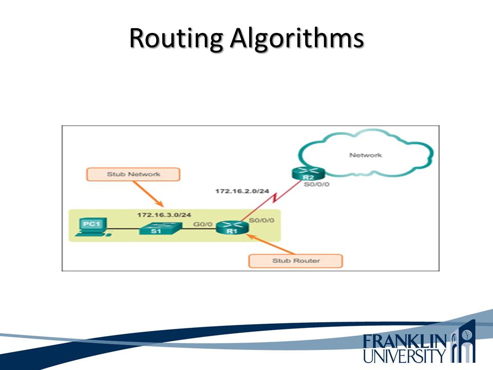
Routing Algorithms Stub network has only one default path to non-local hosts and no outside network knowledge. Non-local stub network traffic uses a single logical path when traveling in and out of the network. A good example would be an individual or group that uses only one router to link to an internet service provider (ISP). The individual or group are considered stub networks by the ISP.
. The individual or group are considered stub networks by the ISP..")
37
Routing Algorithms

39
The default route is the IP address of the next hop when no other routes are known. To configure the default route to be 192.168.1.1: config t ip route 0.0.0.0 0.0.0.0 192.168.1.1 An interface can be used as an alternative to and IP address. To use serial0/0 for destinations not in the routing table, use: ip route 0.0.0.0 0.0.0.0 serial 0/0

40
Routing Algorithms A default route of a computer that is participating in computer networking is the packet forwarding rule (route) taking effect when no other route can be determined for a given Internet Protocol (IP) destination address. All packets for destinations not established in the routing table are sent via the default route. This route generally points to another router, which treats the packet the same way: If a route matches, the packet is forwarded accordingly, otherwise the packet is forwarded to the default route of that router. The process repeats until a packet is delivered to the destination. Each router traversal counts as one hop in the distance calculation for the transmission path.

41
Routing Algorithms

42
Cisco’s On- Demand Routing The Cisco Discovery Protocol (CDP) is a Cisco proprietary protocol that, among other things, is used to discover other Cisco devices on either broadcast or non-broadcast media. CDP provides administrators with information that includes the IP address, software version, as well as the capabilities of the neighbor device. On-Demand Routing (ODR) is an enhancement to Cisco Discovery Protocol that advertises the connected IP prefix or prefixes of a stub router via CDP. ODR also supports VLSM (Variable Length Subnet Mask), which means that it can be used in just about any network.
 is an enhancement to Cisco Discovery Protocol that advertises the connected IP prefix or prefixes of a stub router via CDP. ODR also supports VLSM (Variable Length Subnet Mask), which means that it can be used in just about any network..")
43
Routing Algorithms Cisco’s On- Demand Routing ODR is a feature that provides IP routing for stub sites, with minimum overhead. The overhead of a general, dynamic routing protocol is avoided without incurring the configuration and management overhead of static routing. A stub router can be thought of as a spoke router in a hub-and-spoke network topology where the only router to which the spoke is adjacent is the hub router. In such a network topology, the IP routing information required to represent this topology is fairly simple. These stub routers commonly have a WAN connection to the hub router, and a small number of LAN network segments (stub networks) are directly connected to the stub router.
 are directly connected to the stub router..")
44
Routing Algorithms Cisco’s On- Demand Routing It is important to know that ODR is not a routing protocol. Instead, it is simply an enhancement to CDP that is used to dynamically propagate routing information at Layer 2. The primary reasons ODR is often incorrectly referred to as a routing protocol is because it allows routers to dynamically exchange routing information. The second reason is because ODR is enabled using the router odr global configuration command.

45
Routing Algorithms ODR allows routing information from hub/spoke topology to be exchanged with hub and entered into hub routing table without running any standard routing protocol. ODR (On Demand Routing) is designed to be used in a partially meshed environment (e.g Frame Relay networks) where a hub router maintains one link each to multiple stub routers (spokes routers). Therefore, for any spoke to communicate with another spoke, such traffic must pass through the hub. If each stub networks is simply made up of the stub router and multiple hosts (much like remote location of a corporate organization). There is no need to run any routing protocols on the stub since all host are connected and the routes can be exchanged with hub router using ODR. Hub will henceforth install the routes in routing/forwarding tables as connected routes with next-hop address of each stub respectively.
 is designed to be used in a partially meshed environment (e.g Frame Relay networks) where a hub router maintains one link each to multiple stub routers (spokes routers). Therefore, for any spoke to communicate with another spoke, such traffic must pass through the hub. If each stub networks is simply made up of the stub router and multiple hosts (much like remote location of a corporate organization). There is no need to run any routing protocols on the stub since all host are connected and the routes can be exchanged with hub router using ODR. Hub will henceforth install the routes in routing/forwarding tables as connected routes with next-hop address of each stub respectively..")
46
Routing Algorithms ODR uses CDP protocol that runs, by default on all Cisco devices. CDP is used by Cisco devices to learn & retrieve basic information about their connected neighbors. Therefore, disabling CDP on a router will also disable propagation of ODR traffic.

47
Routing Algorithms

48
Cisco’s On- Demand Routing The primary benefits of using ODR is that it is not CPU intensive and it consumes very little bandwidth.

49
Routing Algorithms Cisco’s On- Demand Routing

50
Static Routing Example RouterA(config)#ip route 172.16.50.0 255.255.255.0 172.16.20.2 Send packets for subnet 50 to 172.16.20.2 (Router B) e0 s0s1 s0 Router ARouter BRouter C Host AHost CHost B 172.16.10.2172.16.30.2172.16.50.2 172.16.20.1172.16.40.1 172.16.10.1172.16.30.1172.16.50.1 172.16.20.2172.16.40.2
#ip route Send packets for subnet 50 to (Router B) e0 s0s1 s0 Router ARouter BRouter C Host AHost CHost B")
51
Default Routing Example Interior Routing Protocols RIPv1 – classful RIPv2 – classless OSPF – Build an entire topology ISIS – IGRP – older CISCO protocol EIGRP – Enhanced Interior CISCO protocol Exterior Routing Protocol BGP

52
Default Routing Example Routing Protocols Provide 1.Discovery of new networks 2.Automatic route updating 3.Best path determination 4.Failover – load balancing 5.Eliminates human error

53
Default Routing Example Distance Vector Routing Protocols Neighboring routers communicate with each other to keep their routing tables updated. A view of the entire network is through all routers connected together. Link State Routing Protocols Share link information (up or down) build a routing table based on the topology that has been built.
 build a routing table based on the topology that has been built..")
54
Default Routing

55
Default Routing Example RouterA(config)#ip route 0.0.0.0 0.0.0.0 172.16.20.2 If it’s not local, send it to 172.16.20.2 (Router B) e0 s0s1 s0 Router ARouter BRouter C Host AHost CHost B 172.16.10.2172.16.30.2172.16.50.2 172.16.20.1172.16.40.1 172.16.10.1 172.16.30.1172.16.50.1 172.16.20.2172.16.40.2
#ip route If it’s not local, send it to (Router B) e0 s0s1 s0 Router ARouter BRouter C Host AHost CHost B")
56
Distance-Vector Routing Router maintains a routing table that lists known networks, direction (vector) to each network, and the distance to each network Router periodically (every 30 seconds, for example) transmits the routing table via a broadcast packet that reaches all other routers on the local segments Routers update their routing table, if necessary, based on received broadcasts
 to each network, and the distance to each network Router periodically (every 30 seconds, for example) transmits the routing table via a broadcast packet that reaches all other routers on the local segments Routers update their routing table, if necessary, based on received broadcasts")
57
Distance-Vector Routing Tables Router A Router B 172.16.0.0192.168.2.0 NetworkDistanceSend To 172.16.0.0 0 Port 1 192.168.2.0 1 Router B NetworkDistanceSend To 192.168.2.0 0 Port 1 172.16.0.0 1 Router A Router A’s Routing TableRouter B’s Routing Table

58
Link-State Routing Routers send updates only when there’s a change Router that detects change creates a link-state advertisement (LSA) and sends it to neighbors Neighbors propagate the change to their neighbors Routers update their topological database if necessary
 and sends it to neighbors Neighbors propagate the change to their neighbors Routers update their topological database if necessary")
59
Distance-Vector Vs. Link-State Distance-vector algorithms keep a list of networks, with next hop and distance (metric) information Link-state algorithms keep a database of routers and links between them – Link-state algorithms think of the internetwork as a graph instead of a list – When changes occur, link-state algorithms apply Dijkstra’s shortest-path algorithm to find the shortest path between any two nodes Dijkstra’s shortest-path algorithm
 information Link-state algorithms keep a database of routers and links between them – Link-state algorithms think of the internetwork as a graph instead of a list – When changes occur, link-state algorithms apply Dijkstra’s shortest-path algorithm to find the shortest path between any two nodes Dijkstra’s shortest-path algorithm.")
60
Link-State Routing Protocol

61
Choosing Between Distance-Vector and Link-State Choose Distance-Vector Simple, flat topology Hub-and-spoke topology Junior network administrators Convergence time not a big concern Choose Link-State Hierarchical topology More senior network administrators Fast convergence is critical

62
Choosing between Distance Vector and Link State Protocols Distance-Vector Routing Information Protocol (RIP) Version 1 and 2 Interior Gateway Routing Protocol (IGRP) Enhanced IGRP Border Gateway Protocol (BGP) Link-State Open Shortest Path First (OSPF) Intermediate System-to- Intermediate System (IS-IS)
 Version 1 and 2 Interior Gateway Routing Protocol (IGRP) Enhanced IGRP Border Gateway Protocol (BGP) Link-State Open Shortest Path First (OSPF) Intermediate System-to- Intermediate System (IS-IS)")
63
Routing Protocols Routers talk to routers on the network, sharing information with each other. Routed protocol: IP Routing protocol: A protocol used by a router. Distance Vector routing protocols include RIP, RIPv1, RIPv2, IGRP, and EIGRP Routers communicate with neighboring routers. Distance = Metric

64
Routing Protocols Link State routing protocols include OSPF and ISIS Routers communicate with all other routers. They exchange link state information to build a topology of the entire network. What direction of interface are you going out of? Link State refers to the interface connections or “links” to other routers and networks.

65
Routing Protocols Convergence is when all routers in the network have the same picture of the network.

66
Routing Information Protocol (RIP) First standard routing protocol developed for TCP/IP environments – RIP Version 1 is documented in RFC 1058 (1988) – RIP Version 2 is documented in RFC 2453 (1998) Easy to configure and troubleshoot Broadcasts its routing table every 30 seconds; 25 routes per packet Uses a single routing metric (hop count) to measure the distance to a destination network; max hop count is 15
 First standard routing protocol developed for TCP/IP environments – RIP Version 1 is documented in RFC 1058 (1988) – RIP Version 2 is documented in RFC 2453 (1998) Easy to configure and troubleshoot Broadcasts its routing table every 30 seconds; 25 routes per packet Uses a single routing metric (hop count) to measure the distance to a destination network; max hop count is 15")
67
RIP V2 Features Includes the subnet mask with route updates – Supports prefix routing (classless routing, super netting) – Supports variable-length subnet masking (VLSM) Includes simple authentication to foil crackers from sending routing updates.
 – Supports variable-length subnet masking (VLSM) Includes simple authentication to foil crackers from sending routing updates.")
68
IGRP Solved Problems with RIP 15-hop limitation in RIP – IGRP supports 255 hops Reliance on just one metric (hop count) – IGRP uses bandwidth, delay, reliability, load – (By default just uses bandwidth and delay) RIP's 30-second update timer – IGRP uses 90 seconds
 – IGRP uses bandwidth, delay, reliability, load – (By default just uses bandwidth and delay) RIP s 30-second update timer – IGRP uses 90 seconds")
69
EIGRP Adjusts to changes in internetwork very quickly Incremental updates contain only changes, not full routing table Updates are delivered reliably Router keeps track of neighbors’ routing tables and uses them as feasible successor Same metric as IGRP, but more granularity (32 bits instead of 24 bits)
")
70
Open Shortest Path First (OSPF) Open standard, defined in RFC 2328 Adjusts to changes quickly Supports very large internetworks Does not use a lot of bandwidth Authenticates protocol exchanges to meet security goals Is an IP routing protocol that is completely link state.
 Open standard, defined in RFC 2328 Adjusts to changes quickly Supports very large internetworks Does not use a lot of bandwidth Authenticates protocol exchanges to meet security goals Is an IP routing protocol that is completely link state.")
71
OSPF Metric A single dimensionless value called cost. A network administrator assigns an OSPF cost to each router interface on the path to a network. The lower the cost, the more likely the interface is to be used to forward data traffic. On a Cisco router, the cost of an interface defaults to 100,000,000 divided by the bandwidth for the interface. For example, a 100-Mbps Ethernet interface has a cost of 1.

72
OSPF Areas Connected via Area Border Routers (ABRs) Area 1Area 3Area 2 Area 0 (Backbone) ABR
 Area 1Area 3Area 2 Area 0 (Backbone) ABR")
73
IS-IS Intermediate System-to-Intermediate System. Link-state routing protocol. Designed by the ISO for the OSI protocols. Integrated IS-IS handles IP also.

74
IS-IS IS-IS is a routing protocol designed to move information efficiently within a computer network, a group of physically connected computers or similar devices. It accomplishes this by determining the best route for datagrams through a packet-switched network. The protocol was defined in ISO/IEC 10589:2002 as an international standard within the Open Systems Interconnections (OSI) reference design
 reference design.")
75
Border Gateway Protocol (BGP) Allows routers in different autonomous systems to exchange routing information – Exterior routing protocol – Used on the Internet among large ISPs and major companies Supports route aggregation Main metric is the length of the list of autonomous system numbers, but BGP also supports routing based on policies
 Allows routers in different autonomous systems to exchange routing information – Exterior routing protocol – Used on the Internet among large ISPs and major companies Supports route aggregation Main metric is the length of the list of autonomous system numbers, but BGP also supports routing based on policies")
76
Border Gateway Protocol (BGP)
")
77
Internet Protocol (EGP) During the early days of the Internet, EGP version 3 (EGP3) was used to interconnect Autonomous Systems. Currently, BGP version 4 is the accepted standard for Internet routing and has essentially replaced the more limited EGP3.

78
Internet Control Message Protocol (ICMP) ICMP works at the Network layer and is used by IP for many different services. ICMP is a management protocol and messaging service for IP. Its messages are carried as IP datagrams.

79
Routing Protocols Summary Distant vector: RIP and IGRP Link-state: OSPF Hybrid: EIGRP

80
Summary The selection of switching and routing protocols should be based on an analysis of – Goals – Scalability and performance characteristics of the protocols Transparent bridging is used on modern switches – But other choices involve enhancements to STP and protocols for transporting VLAN information There are many types of routing protocols and many choices within each type

81
Review Questions What are some options for enhancing the Spanning Tree Protocol? What factors will help you decide whether distance-vector or link-state routing is best for your design customer? What factors will help you select a specific routing protocol? Why do static and default routing still play a role in many modern network designs?

82
This Week’s Outcomes Spanning Tree Protocol Rapid Spanning Tree Protocol Static versus Dynamic Routing Routing Protocols and Characteristics

83
Due this week 6-1 – Concept questions 5

84
Q & A Questions, comments, concerns?

Similar presentations


>")
 –Address Resolution (8.2) –Routing Protocols (8.3) –Administrative Classification (8.4)>")


 of Dynamic Routing Protocols: – Dynamically share information between routers (Discover remote networks). – Automatically.>")


