Download presentation
Presentation is loading. Please wait.

1
Chapter 6 - (Extrusion)
")
2
Extrusion A cylindrical billet is forced through a die (‘push’) Extrusion is the process by which a block/billet of metal is reduced in cross section by forcing it to flow through a die orifice under high pressure. A round billet is placed in a chamber and forced through a die opening. The die opening may be round or of various other shapes.

3
Extrusion Extrusion is a process used to create an objects of a fixed cross-sectional profile. A material is pushed through a die of the desired cross-section. The two main advantages of this process over other bulk deformation processes is: its ability to create very complex cross-sections and to work materials that are brittle, because the material only encounters compressive and shear stresses. It also forms parts with an excellent surface finish Process is similar to squeezing toothpaste out of a toothpaste tube In general, extrusion is used to produce long parts of uniform cross sections and complex shape

4
Extrusion Large deformations can take place without fracture because material is under triaxial compression The reaction of the extrusion billet with the container and die results in high compressive stresses which are effective in reducing cracking of materials during primary breakdown from the ingot. This helps to increase the utilization of extrusion in the working of metals that are difficult to form like stainless steels, nickel-based alloys, and other high-temperature materials. However, better surface finish and higher strengths (strain hardened metals) are provided by cold extrusion.
 are provided by cold extrusion.")
5
Extrusion Process The process begins by heating stock material ( for hot or warm extrusion). It is then loaded into container in the press. A dummy plate is placed behind it where the ram then presses on the material to push it out of the die. The extrusion ratio is defined as the starting cross-sectional area divided by the cross-sectional of the final extrusion. One of the main advantages of extrusion process is that this ratio can be very large while still producing quality parts Commonly extruded materials include metals, polymers, ceramics, concrete. Materials that can be extruded are aluminum, copper, steel, magnesium, and plastic. Aluminum, copper and plastic are most suitable for extrusion
. It is then loaded into container in the press. A dummy plate is placed behind it where the ram then presses on the material to push it out of the die. The extrusion ratio is defined as the starting cross-sectional area divided by the cross-sectional of the final extrusion. One of the main advantages of extrusion process is that this ratio can be very large while still producing quality parts. Commonly extruded materials include metals, polymers, ceramics, concrete. Materials that can be extruded are aluminum, copper, steel, magnesium, and plastic. Aluminum, copper and plastic are most suitable for extrusion.")
6
Advantages of Extrusion
Extrusion results in better Better grain structure Better accuracy and Surface finish of the components. Less wastage of material in extrusion is another attractive feature of extrusion.

7
Advantages of Extrusion
A cross section of the metal part in Fig., showing the grain flow pattern.

8
Extrusion It can be hot or cold depending on the ductility of the material. Extrusion may be continuous (theoretically producing long material) or semi-continuous (producing many pieces because each piece is extruded individually) The products of extrusion are generally called "extrudates". Tool costs are generally low. Examples: solid and hollow shapes, railings for sliding doors, window frames, tubing [various, constant, cross sections], aluminum ladders, gears.
 or semi-continuous (producing many pieces because each piece is extruded individually) The products of extrusion are generally called extrudates . Tool costs are generally low. Examples: solid and hollow shapes, railings for sliding doors, window frames, tubing [various, constant, cross sections], aluminum ladders, gears.")
9
Continuous and semi-continuous extrusion

10
Extrusion products Typical parts produced by extrusion are trim parts used in automotive and construction applications, window frame members, railings for sliding doors, aircraft structural parts. Example: Aluminum extrusions are used in commercial and domestic buildings for window and door frame systems, prefabricated houses/building structures, roofing and curtain walling, shop fronts, etc. Furthermore, extrusions are also used in transport for airframes, and in marine applications.

13
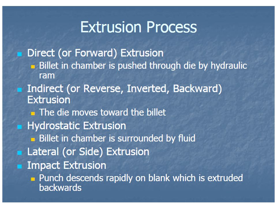
Classification of extrusion processes

14
Direct Extrusion (Forward)
Similar to forcing toothpaste through the opening of tube In this process the billet slides relative to container wall Final cross-sectional shape of extrudate is determined by die opening shape. As ram approaches die opening, a small portion of billet remains that cannot be forced through the die This portion, called the butt, must be separated from the extrudate by cutting it off just beyond the die exit

15
Direct Extrusion (Forward)
Direct extrusion, also called forward extrusion, is a process in which is the billet moves along the same direction as the ram or punch do. Sliding of billet is against stationary container wall. Friction between the container and billet is high. As a result, greater forces are required. A dummy block of slightly lower diameter than the billet diameter is used in order to prevent oxidation of the billet in hot extrusion. Hollow sections like tubes can be extruded by direct method, by using hollow billet and a mandrel attached to the dummy block.

16
Direct Extrusion(Forward)
The metal billet is placed in a container and driven through the die by the ram. The dummy block or pressure plate, is placed at the end of the ram in contact with the billet. Friction is at the die and container wall requires higher pressure than indirect extrusion.

18
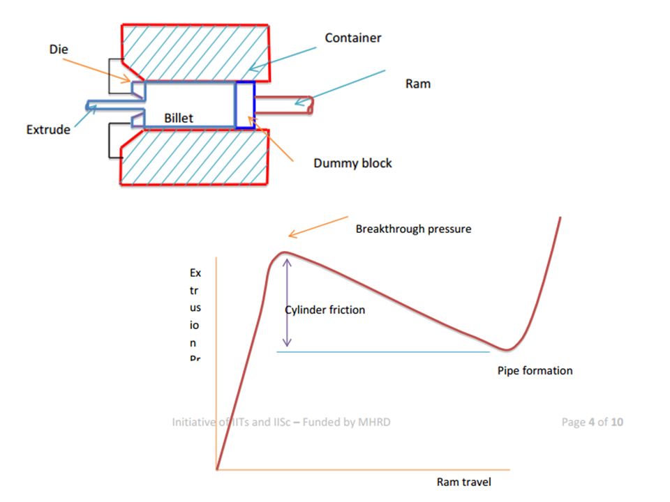
Variation of extrusion force with ram travel in direct extrusion
Extrusion force, which is the force required for extrusion, in direct extrusion, varies with ram travel as shown in figure. Initially the billet gets compressed to the size of container, before getting extruded. Also, initially static friction exists between billet and container. As a result the extrusion pressure or force increases steeply as shown. Once the billet starts getting extruded, it length inside the container is reduced. Friction between billet and container now starts reducing. Therefore, extrusion pressure reduces.

19
Variation of extrusion force with ram travel in direct extrusion
The highest pressure at which extrusion starts is called breakthrough pressure. At the end of the extrusion, the small amount of material left in the container gets pulled into the die, the extrusion pressure rapidly increases, as the small size billet present offers higher resistance. As the length of the billet is increased, the corresponding extrusion pressure is also higher because of friction between container and billet Therefore, billet lengths beyond 5 times the diameter are not preferred in direct extrusion. Direct extrusion can be employed for extruding solid circular or non-circular sections, hollow sections such as tubes or cups.

20
Hollow and Semi-Hollow Shapes
Direct Extrusion (Forward) Hollow and Semi-Hollow Shapes (a) Direct extrusion to produce hollow or semi-hollow cross sections; (b) hollow and (c) semi-hollow cross sections
 Hollow and Semi-Hollow Shapes. (a) Direct extrusion to produce hollow or semi-hollow cross sections; (b) hollow and (c) semi-hollow cross sections.")
21
Direct Extrusion (Forward)
Process variables in direct extrusion. The die angle Reduction in cross section Extrusion speed Billet temperature, and Lubrication all affect the extrusion pressure.

22
Extrusion Force Force, F, depends on: Strength of billet material
Extrusion Ratio, R, Ao/Af Friction between billet and chamber & die surfaces Process variables: temperature, velocity The Extrusion constant, k, is determined experimentally, see the next figure

23
Extrusion Force Extrusion constant k for various metals at different temperatures.

24
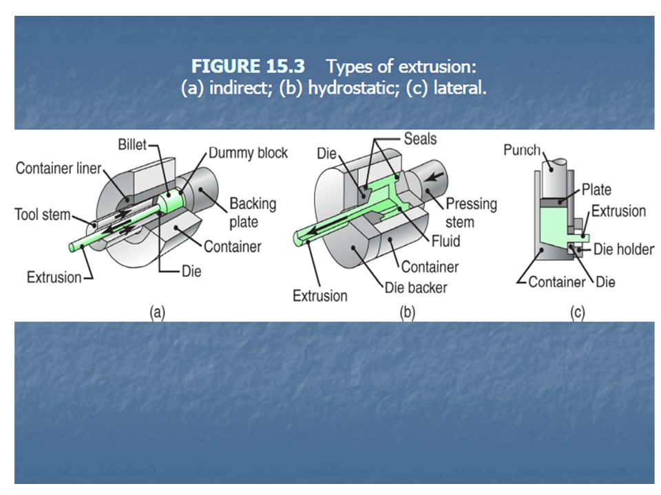
Indirect Extrusion (Backward)
Indirect extrusion (backward extrusion) is a process in which punch moves opposite to that of the billet. Here there is no relative motion between container and billet. Hence, there is less friction and hence reduced forces are required for indirect extrusion. For extruding solid pieces, hollow punch is required. In hollow extrusion, the material gets forced through the annular space between the solid punch and the container.
 is a process in which punch moves opposite to that of the billet. Here there is no relative motion between container and billet. Hence, there is less friction and hence reduced forces are required for indirect extrusion. For extruding solid pieces, hollow punch is required. In hollow extrusion, the material gets forced through the annular space between the solid punch and the container.")
25
Indirect Extrusion(Backward)
The variation of extrusion pressure in indirect extrusion is shown. As seen, extrusion pressure for indirect extrusion is lower than that for direct extrusion. Many components are manufactured by combining direct and indirect extrusions. Indirect extrusion can not be used for extruding long extrudes.

26
Indirect Extrusion (Backward)
The die moves toward the billet and there is no relative motion at the billet-container interface except the die. Friction at the die only (no relative movement at the container wall) - requires roughly constant pressure.
 - requires roughly constant pressure.")
27
Indirect Extrusion (Backward)
Indirect extrusion to produce (a) a solid cross section and (b) a hollow cross section
 a solid cross section and (b) a hollow cross section.")
28
Indirect Extrusion(Backward)
Limitations of indirect extrusion are imposed by Lower rigidity of hollow ram Difficulty in supporting extruded product as it exits die While friction is a factor in determining the ram force in direct extrusion, but is not a factor in indirect extrusion.

29
Indirect Extrusion(Backward)
")
30
Extrusion Types of Extrusion Hot Extrusion Cold Extrusion

31
Hot Extrusion Generally done at fairly high temperatures, approximately at 50 to 75 % of the melting point of the metal. which means it is done above the material's recrystallization temperature to keep the material from work hardening and to make it easier to push the material through the die. Hot extrusion can be employed for higher extrusion ratios.[ Purpose] Inhomogeneous deformation can occur due to die wall chilling of the billet. Metal may get oxidized. The oxide layer can increase friction as well as the material flow.

32
Hot Extrusion Use higher temperatures to improve ductility & metal flow Can cause excessive die wear, result of abrasion from surface oxides Can have nonuniform deformation caused by cooling surfaces of billet and die Improve by preheating die and wall container. Surface oxides on product may be undesirable when good surface finish is important Can prevent extrusion of surface oxides by making the diameter of the dummy block a little smaller than the container; this keeps a thin shell (“skull”) of oxides in the container
 of oxides in the container.")
33
Hot Extrusion The high temperatures and pressures has an adverse effect on the die life as well as other components so good lubrication is a must. Oil graphite and glass powder is preferred as lubricants. Pressures range from 30 to 700 MPa (4,400 to 101,500 psi), therefore lubrication is required, which can be oil graphite for lower temperature extrusions, or glass powder for higher temperature extrusions
, therefore lubrication is required, which can be oil graphite for lower temperature extrusions, or glass powder for higher temperature extrusions.")
34
Extrusion Temperature Ranges for Various Metals
Die material for hot extrusion: Die materials for hot extrusion are hot-worked die steels. Coatings (such as partially stabilized zirconia) may be applied to the dies to extend their life.
 may be applied to the dies to extend their life.")
35
Hot Extrusion It is carried out at elevated temperature for metals and alloys that do not have sufficient ductility at room temperature or in order to reduce the forces required [ Purpose] . Problems: Die wear .Billet develops an oxide film because of heating. Oxide film is abrasive Cooling of the surface of the hot billet in the container (which is normally not heated) can result in highly nonuniform deformation during extrusion. Billet develops an oxide film because of heating. Oxide film is abrasive, can affect the flow pattern of the material, may result in an extruded product that is unacceptable when a good surface finish is important.
 can result in highly nonuniform deformation during extrusion. Billet develops an oxide film because of heating. Oxide film is abrasive, can affect the flow pattern of the material, may result in an extruded product that is unacceptable when a good surface finish is important.")
36
Hot Extrusion Furthermore, since the billet is heated prior to extrusion, it is typically covered with an oxide layer, unless heated in an inert atmosphere. The oxide layer affects the frictional properties, can affect the flow of the material, and can produce an extruded part that is covered with an oxide layer. Lubrication. It is important because it affects on: Material flow during extrusion. Surface finish and integrity. Product quality. Extrusion forces.

37
Hot Extrusion lubricants
For steels, stainless steel, and high temperate materials, glass is a good excellent lubrication. Glass maintains its viscosity at elevated temperatures. Has good wetting characteristics, And act as a thermal barrier between the billet, the container, and the die, thus minimizing cooling. Glass applied as powder to billet surface, or Insert glass pad at die entrance; when heated,melted glass lubricates die surface

38
Effects of temperature on hot extrusion
Decreased deformation resistance due to increasing extrusion temperature. Oxidation of billet and extrusion tools. Softening of dies and tools. Difficult to provide adequate lubrication.

39
Hot Extrusion The top working temperature should be safely below the melting point. Use minimum temperature to provide metal with suitable plasticity. The temperature of the workpiece in metal working depends on; The initial temperature of the tools and the materials Heat generated due to plastic deformation Heat generated by friction at the die/material interface (highest) Heat transfer between the deforming material and the dies and surrounding environment. Note: Working temperature in extrusion is normally higher than used in forging and rolling due to relatively large compressive stresses in minimizing cracking.
 Heat transfer between the deforming material and the dies and surrounding environment. Note: Working temperature in extrusion is normally higher than used in forging and rolling due to relatively large compressive stresses in minimizing cracking.")
40
Cold Extrusion Many ductile metals can be cold extruded into various configurations, with the billet mostly at room temperature [Cold extrusion is the process done at room temperature or near room temperature]. Examples of the metals that can be extruded are lead, tin, aluminum alloys, copper, titanium, molybdenum, vanadium. Typical product made are automotive components and gear blanks. In automobile sector they have found wide applications in Injection technology; Engine control; Fuel supply; Automatic transmissions technology (gear blanks); Safety restraint systems (SRS). SRS connectors play a key role in your safety
; Safety restraint systems (SRS). SRS connectors play a key role in your safety.")
41
Cold Extrusion Production steps for a cold extruded spark plug

42
Cold Extrusion Work hardening leads to improved properties, as long as frictional heat does not cause recrystallization Improved surface finish due to lack of oxide film Advantages vs. Hot Extrusion No oxidation takes place. Good mechanical properties resulting from strain hardening as long as the temperatures created (heat generated by plastic deformation and friction) are below the recrystallization temperature. Good surface finish (due to lack of oxide film) with the use of proper lubricants. High production rate and relatively low cost Less energy required (no preheating) Good dimensional tolerances, thus requiring a minimum of machining and finishing operations. SRS connectors play a key role in your safety
 are below the recrystallization temperature. Good surface finish (due to lack of oxide film) with the use of proper lubricants. High production rate and relatively low cost. Less energy required (no preheating) Good dimensional tolerances, thus requiring a minimum of machining and finishing operations. SRS connectors play a key role in your safety.")
43
Cold Extrusion Disadvantage:
Higher stresses on tooling and dies (Especially with steel workpieces) Thus, the design of tooling and selection of appropriate tool materials are crucial to success in cold extrusion. The hardness of tooling usually ranges between 60 and 65 HRC for the punch (ram), and 58 to 62 HRC for the dies. The punches are critical component; they must have sufficient strength, toughness, and resistance to wear and fatigue
 Thus, the design of tooling and selection of appropriate tool materials are crucial to success in cold extrusion. The hardness of tooling usually ranges between 60 and 65 HRC for the punch (ram), and 58 to 62 HRC for the dies. The punches are critical component; they must have sufficient strength, toughness, and resistance to wear and fatigue.")
44
Cold Extrusion Lubrication is important for this process because new surfaces are generated during deformation, which may cause seizure between the workpiece and tooling. The most effective lubrication is provided by phosphate conversion coatings on the workpiece and with soap or wax as lubrication. Temperature rise in cold extrusion is an important factor, especially at high extrusion ratio. The temperature may be sufficiently high to initiate and complete recrystallization process of cold-worked metal, thus reducing the advantages of cold working

45
Force in Cold Extrusion

46
By equipment Extrusion
Horizontal Hydraulic Press Can control stroke & speed Can apply constant force over long stroke Vertical Hydraulic Press Used for cold extrusion Lower capacity

47
By equipment Extrusion
Horizontal presses • Used for most commercial extrusion of bars and shapes. Disadvantages: Deformation is non-uniform due to different temperatures between top and bottom parts of the billet. Proper alignment is needed Floor space is needed

48
By equipment Extrusion
2) Vertical presses Chiefly used in the production of thin-wall tubing. Advantages: • Easier alignment between the press ram and tools. • Higher rate of production. • Require less floor space than horizontal presses. • Uniform deformation.
 Vertical presses. Chiefly used in the production of thin-wall tubing. Advantages: • Easier alignment between the press ram and tools. • Higher rate of production. • Require less floor space than horizontal presses. • Uniform deformation.")
49
By equipment Extrusion
Vertical extrusion presses Requirements: • Need considerable headroom to make extrusions of appreciable length. • A floor pit is necessary for providing rigidity for the machine. Vertical extrusion machine

50
Miscellaneous Extrusion Operations.
Impact extrusion Is a form of indirect extrusion and is particularly suitable for hollow shapes. The process – often - included in the category of cold extrusion (Often a combination of indirect and cold extrusion). In this operation, the punch descends at a high speed and strikes the blank and extrude it in the opposite direction. A typical example of impact extrusion is the production of collapsible tubes, such as for toothpaste.
. In this operation, the punch descends at a high speed and strikes the blank and extrude it in the opposite direction. A typical example of impact extrusion is the production of collapsible tubes, such as for toothpaste.")
51
Impact extrusion product

52
Impact extrusion product
Schematic illustration of the impact-extrusion process. The extruded parts are stripped by the use of a stripper plate, because they tend to stick to the punch.

53
Impact extrusion product
It should be noted that the thickness of the extruded tubular cross section is a function of the clearance between the punch and the die cavity (Thickness of extruded part depends on clearance between punch and die). The impact-extrusion process typically produces tubular shapes with wall thicknesses that are small in relation to their diameters, a ratio that can be as a small as 0.005
. The impact-extrusion process typically produces tubular shapes with wall thicknesses that are small in relation to their diameters, a ratio that can be as a small as")
54
Impact extrusion product
The concentricity of the punch and blank is important as otherwise the wall thickness will not be uniform. A variety of nonferrous metals are impact extruded in this manner The equipment used is typically vertical presses at production rate as high as two parts per second

55
(a) Impact extrusion of a collapsible tube.
(b) and (c) Two examples of products made by impact extrusion. These parts also may be made by casting, forging, or machining. The choice of process depends on the materials involved, part dimensions and wall thickness, and the properties desired. Economic considerations also are important in final process selection.
 and (c) Two examples of products made by impact extrusion. These parts also may be made by casting, forging, or machining. The choice of process depends on the materials involved, part dimensions and wall thickness, and the properties desired. Economic considerations also are important in final process selection.")
56
Miscellaneous Extrusion Operations - Hydrostatic Extrusion
. In this process, the pressure required for extrusion is supplied through a fluid medium that surrounds the billet. Thus, there is no container-wall contact and hence no friction. The high pressure in the chamber also transmits some of the fluid to die surfaces, significantly reducing friction and forces.

57
Miscellaneous Extrusion Operations.
Hydrostatic Extrusion The pressure in this process is in the order of 1400 Mpa Because of the highly pressurized environment and fluid medium, this operation reduces the defects that may otherwise develop in the extruded product. A variety of metals and polymer have been extruded successfully, such as tubes, solid shapes, clad profiles and other hollow shapes. Hydrostatic extrusion is usually carried out at room temperature, typically using vegetable oils as the fluid, particularly castor oil because its good lubricant and its viscosity is not influenced significantly by pressure

58
Miscellaneous Extrusion Operations.
Clad profiles

59
Miscellaneous Extrusion Operations.
For elevated temperature hydrostatic extrusion, waxes, polymers, and glasses are used as the fluid; these materials also serve as thermal insulators and help maintain the billet temperature during extrusion Hydrostatic extrusion has had limited industries applications: Because of the somewhat complex nature of tooling The experience required in working with high pressure The design of specialize equipment Long cycle times required A practical limit on fluid pressure of a round 1.7Gpa.

60
Miscellaneous Extrusion Operations.
Hydrostatic Extrusion Advantages Eliminating of large friction force between billet and the container wall. Possible to use die with very small angle

61
Miscellaneous Extrusion Operations.
Hydrostatic Extrusion Brittle materials can be extruded successfully by this method because the hydrostatic pressure (along with low friction and the use of small die angles and high extrusion ratios (R = A0/Af) increases the ductility of the material. It has limited applications because it is uneconomical
 increases the ductility of the material. It has limited applications because it is uneconomical.")
62
Extrusion Ratio Also called the reduction ratio, it is defined as:
Where: R = Extrusion ratio; Ao = Cross sectional area of the starting billet cross sectional area Af = Final cross-sectional area of the extruded section R Applies to both direct and indirect extrusion

63
Extrusion Ratio Fractional reduction in area, r
Extrusion ratio, R, is the ratio of the initial cross-sectional area , Ao, of the billet to the final cross-sectional area , Af, after extrusion. Fractional reduction in area, r Rewrite the extrusion ratio R

64
Pressure in extrusion Extrusion pressure = extrusion force /cross sectional area The rapid rise in pressure during initial ram travel is due to the initial compression of the billet to fill the extrusion container. For direct extrusion, the metal begins to flow through the die at the maximum pressure, the breakthrough pressure. • As the billet extrudes through the die the pressure required to maintain flow progressively decreases with decreasing length of the billet in the container. At the end of the stroke, the pressure rises up rapidly in an attempt to exit billet so as to leave a small discard in the container.

65
Force in Hot extrusion For indirect extrusion, extrusion pressure is ~ constant and represent the stress required to deform the metal through the die.

66
Mechanics of Extrusion

67
Direct Extrusion: Ideal force, no friction
Based on the extrusion ratio, the value of true strain: For perfectly plastic material, with a Yield stress Y: the energy dissipated in plastic deformation per unit volume The work done on the billet and the work that is supplied by the ram force, which travels a distance Lo:

68
Direct Extrusion-Ideal force, no friction
By equating the work of plastic deformation to the external work done we have the ideal pressure is: And the ideal force is

69
Direct Extrusion: ideal force with friction
For smaller dies angels, It was shown that with friction at the die-billet interface and ignoring the container-wall friction. The extrusion pressure is: Because of the dead zone formed, the material flows along a 45o die angle. So pressure can be estimated as:

70
Direct Extrusion: ideal force with friction
Note that as the ram travels further toward the die, L, decreases, and thus the pressure, as shown in the figure. However, in indirect extrusion, the extrusion pressure is not a function of billet length

71
Direct Extrusion: Actual Forces
In actual extrusion practices, there are difficulties in estimating: The coefficient of friction and its variation throughout all work piece-die contacting surfaces. The flow stress of the material under the actual conditions of temperature and strain rate And the work involved in inhomogeneous deformation. A simple empirical formula has been developed in the form of: P=Y( a+ b*lnR) a=0.8, and b ranges between 1.2 and 1.5
 a=0.8, and b ranges between 1.2 and 1.5.")
72
Effect of ram speed and temperature on extrusion pressure
As expected, the pressure increases rapidly with ram speed, especially at elevated temperature due to increase strain-rate sensitivity. However, the heat generated at higher speed will not dissipated fast enough. This rise in temperature can lead to incipient melting of the work piece material and possibly causes defects. Also Speed cracking can be occurred because of the high ram speed. These problems can be reduced by lowering the extrusion speed Extrusion pressure Increasing temperature Extrusion speed

73
Force in Hot extrusion A parameter that is used to estimate the force in hot extrusion is an experimentally determined extrusion constant, k, which includes various factors involved in the process

74
Force in Hot extrusion Extrusion force:
where k = extrusion constant, an overall factor which accounts for the flow stress, friction, and inhomogeneous deformation.. A0: is the billet area. Af: is the extruded product area. R: extrusion ratio Extrusion force depends on: Extrusion ratio Strength of the billet Friction between the billet and the chamber and the die surfaces. The process variables such as temperature of the billet and the speed of extrusion.

75
Extrusion Constant k for Various Metals
Figure Extrusion constant k for various metals at different temperatures. Source: P. Loewenstein.

76
Example Calculation of force in hot extrusion
A round billet made of 70 – 30 brass is extruded at a temperature of 1250 F (675 C). The billet diameter is 5 in. (125mm), and the diameter of the extrusion is 2 in. (50mm). Calculate the extrusion force required.
. The billet diameter is 5 in. (125mm), and the diameter of the extrusion is 2 in. (50mm). Calculate the extrusion force required.")
77
Extrusion Die Features
(a) Definition of die angle; (b) effect of die angle on ram force
 Definition of die angle; (b) effect of die angle on ram force.")
78
Optimum die angle The die angle has an important effect on forces in extrusion. Its effect can be summarized as follows: The ideal force (with no friction) is a function of the strain that the material undergoes, thus a function of extrusion ratio R. consequently, it is independent of die angle, as shown in curve b
 is a function of the strain that the material undergoes, thus a function of extrusion ratio R. consequently, it is independent of die angle, as shown in curve b.")
79
Optimum die angle The force due to friction increases with decreasing die angle. This is because, the length of contact along the billet-die interface increases as the die angle decreases; thus the force required increases as shown in curve d.

80
Optimum die angle An additional force is required for redundant work due to the inhomogeneous deformation of the material during extrusion. This redundant work is assumed to increase with the die angle, because the higher the angle, the more nonuniform the deformation becomes, as shown in curve c

81
Optimum die angle The total extrusion forces is the sum of these three components. Also there is an angle at which this force is a minimum. Because the force is minimized at this angle, it is called the optimum angle

82
Metal flow in extrusion
Types of metal flow in extruding (a) Flow pattern obtained at low friction or in indirect extrusion. (b) Pattern obtained with high friction at the billet–chamber interfaces. (c) Pattern obtained at high friction or with cooling of the outer regions of the billet in the chamber. This type of pattern, observed in metals whose strength increases rapidly with decreasing temperature, leads to a defect known as pipe (or extrusion) defect.
 Flow pattern obtained at low friction or in indirect extrusion. (b) Pattern obtained with high friction at the billet–chamber interfaces. (c) Pattern obtained at high friction or with cooling of the outer regions of the billet in the chamber. This type of pattern, observed in metals whose strength increases rapidly with decreasing temperature, leads to a defect known as pipe (or extrusion) defect.")
83
Metal flow in extrusion
A common technique for investigating the flow pattern is to cut a round billet and mark one face with a square grid pattern. The two halves are then placed together in the container (they may also be fastened together to keep the two halves intact) and extruded as one piece. They are then taken apart and observations are made regarding the distortion of the grid line. The main factors involved in how these different flow patterns develop are: Friction at billet-container and billet- die interfaces Thermal gradients within the billet.
 and extruded as one piece. They are then taken apart and observations are made regarding the distortion of the grid line. The main factors involved in how these different flow patterns develop are: Friction at billet-container and billet- die interfaces. Thermal gradients within the billet.")
84
Metal flow in extrusion
The most homogeneous (uniform) flow pattern is obtained when there is no friction at the billet container-die interfaces (shown in the figure). This type of flow occurs when the lubricant is very effective or with indirect extrusion, where there is no friction at the billet-container interface.
 flow pattern is obtained when there is no friction at the billet container-die interfaces (shown in the figure). This type of flow occurs when the lubricant is very effective or with indirect extrusion, where there is no friction at the billet-container interface.")
85
Metal flow in extrusion
When friction along all interfaces [billet–Wall interfaces] is high a dead-metal zone develops (Fig. 3 b). Note the high-shear area forms as the material flows into the die exit, somewhat like a funnel. This configuration may indicate that the billet surfaces (with their oxide layer and lubricant) could enter this high-shear zone and be extruded, causing defects in the extruded product. When we don’t use an effective lubrication
. Note the high-shear area forms as the material flows into the die exit, somewhat like a funnel. This configuration may indicate that the billet surfaces (with their oxide layer and lubricant) could enter this high-shear zone and be extruded, causing defects in the extruded product. When we don’t use an effective lubrication.")
86
Metal flow in extrusion
The high-shear zone extends farther into the billet (shown in the figure). This situation can be due to high container-wall friction (which retards the flow of the billet on the surface due to heat transfer) or from materials in which the flow stress drops rapidly at the billet surface with increasing heat transfer. In hot working, the material near the container walls cools rapidly and hence increases in strength. Thus the material in the central regions flows toward the die more easily than that at the outer regions. As a result, a large dead-metal zone forms and the flow is inhomogeneous. This flow pattern leads to a defect known as a pipe or extrusion defect. This follow related to thermal gradients within the billet
. This situation can be due to high container-wall friction (which retards the flow of the billet on the surface due to heat transfer) or from materials in which the flow stress drops rapidly at the billet surface with increasing heat transfer. In hot working, the material near the container walls cools rapidly and hence increases in strength. Thus the material in the central regions flows toward the die more easily than that at the outer regions. As a result, a large dead-metal zone forms and the flow is inhomogeneous. This flow pattern leads to a defect known as a pipe or extrusion defect. This follow related to thermal gradients within the billet.")
87
Extrusion defects There are three principal defects in extrusion as described below: Surface cracking: High extrusion temperature, friction, speed cause high surface temperatures [surface temperatures rise significantly and can lead to surface cracking and tearing (Fir-tree cracking or speed cracking)]. In hot extrusion, this form of cracking usually is intergranular (along grain boundaries)and is associated with high temperature Caused by hot shorting: local cooling of constituents or impurities at grain boundaries This situation can be avoided by using lower temperatures and speeds.
]. In hot extrusion, this form of cracking usually is intergranular (along grain boundaries)and is associated with high temperature. Caused by hot shorting: local cooling of constituents or impurities at grain boundaries. This situation can be avoided by using lower temperatures and speeds.")
88
Extrusion defects Surface cracking:
Surface cracking also may occur at lower temperatures where it has been attributed to periodic sticking of the extruded product along the die land during extrusion (At lower temperature, sticking in the die land and the sudden building up of pressure will cause transverse cracking). Caused by sticking of extrusion along die land Sticking raises pressure transverse cracking
. Caused by sticking of extrusion along die land. Sticking raises pressure. transverse cracking.")
89
Extrusion defects 2. Extrusion Defects it can be noted that the type of metal flow as shown will tend to draw surface oxides and impurities toward the center of billet. This defect is known as extrusion defect, pipe, tailpipe, or fishtailing, renders a considerable portion of the extruded materials useless, by as much as one-third the length of the extrusion The metal flow tends to draw surface oxides and impurities toward the center of the billet much likes a funnel.

90
Extrusion defects 2. Extrusion Defects This defect can be reduced by:
Modifying the flow pattern to a less inhomogeneous one to be more uniform, such as by controlling friction and minimizing temperature gradients. Another method is to machine the surface of the billet prior to extrusion to eliminate scale and impurities The extrusion defect can also be avoided by using a dummy block that is smaller in diameter than the container, thus leaving a thin shell along the container wall as extrusion progresses.

91
Extrusion defects 3. Internal Cracking
Cracks variously known as centerburst, center cracking, arrowhead fracture, or chevron cracking, can develop at the center of an extruded product These cracks are attributed to a state of tensile stresses at the centerline of the deformation zone in the die. This situation is similar to the necked region in a uniaxial tensile-test specimen. The major variables affecting this defects are the die angle [Increases with increasing die angle], extrusion ratio [Decreases with increasing extrusion ratio the deformation zones will meet], friction [Decreases with increasing friction], and the die contact length (the smaller the die angle, the longer is the contact length).
.")
92
Chevron Cracking (b) (a) Figure (a) Chevron cracking (central burst) in extruded round steel bars. Unless the products are inspected, such internal defects may remain undetected, and later cause failure of the part in service. This defect can also develop in the drawing of rod, of wire, and of tubes. (b) Schematic illustration of rigid and plastic zones in extrusion. The tendency toward chevron cracking increases if the two plastic zones do not meet.
![]()
93
Extrusion defects Fishtailing

94
Die design Die design is the heart of efficient extrusion production.
Dies must withstand considerable amount of stresses, thermal shock, and oxidation. Die design consideration Wall thickness: different wall thicknesses in one section should be avoided. Sharp or rounded corners: sharp corners should be avoided. Symmetrical: should be more accurate.

95
Die material Dies are made from highly alloy tools steels or ceramics or (zirconia) Heat treatments such as nitriding are required (several times) to increase hardness ( Hv or HRC). This improves die life and avoiding unscheduled press shutdown.
 to increase hardness ( Hv or HRC). This improves die life and avoiding unscheduled press shutdown.")
Similar presentations


>")


 B.Sc (ENGINEERING) LEVEL 2 (Semester 2)>")


