Download presentation
Presentation is loading. Please wait.

1
25 – Wastewater Conveyance System Design April, 23, 2013 Professor Doran CEE 410

2
Learning goals for today are to improve understanding of: Typical building and service connections Types of collecting sewer systems Key design approach for gravity sewers SizeSlopeCover MHsDetailsDrawings Typical gravity sewer layout concepts

3
Learning goals for today are to improve understanding of: Typical building and service connections Types of collecting sewer systems Key design approach for gravity sewers SizeSlopeCover MHsDetailsDrawings Typical gravity sewer layout concepts

4
Learning goals for today are to improve understanding of: Typical building and service connections Types of collecting sewer systems Key design approach for gravity sewers SizeSlopeCover MHsDetailsDrawings Typical gravity sewer layout concepts

5
Learning goals for today are to improve understanding of: Typical building and service connections Types of collecting sewer systems Key design approach for gravity sewers SizeSlopeCover MHsDetailsDrawings Typical gravity sewer layout concepts

6
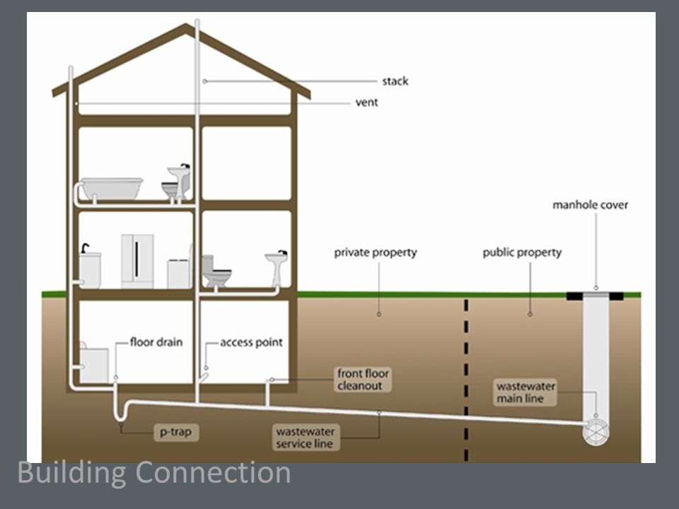
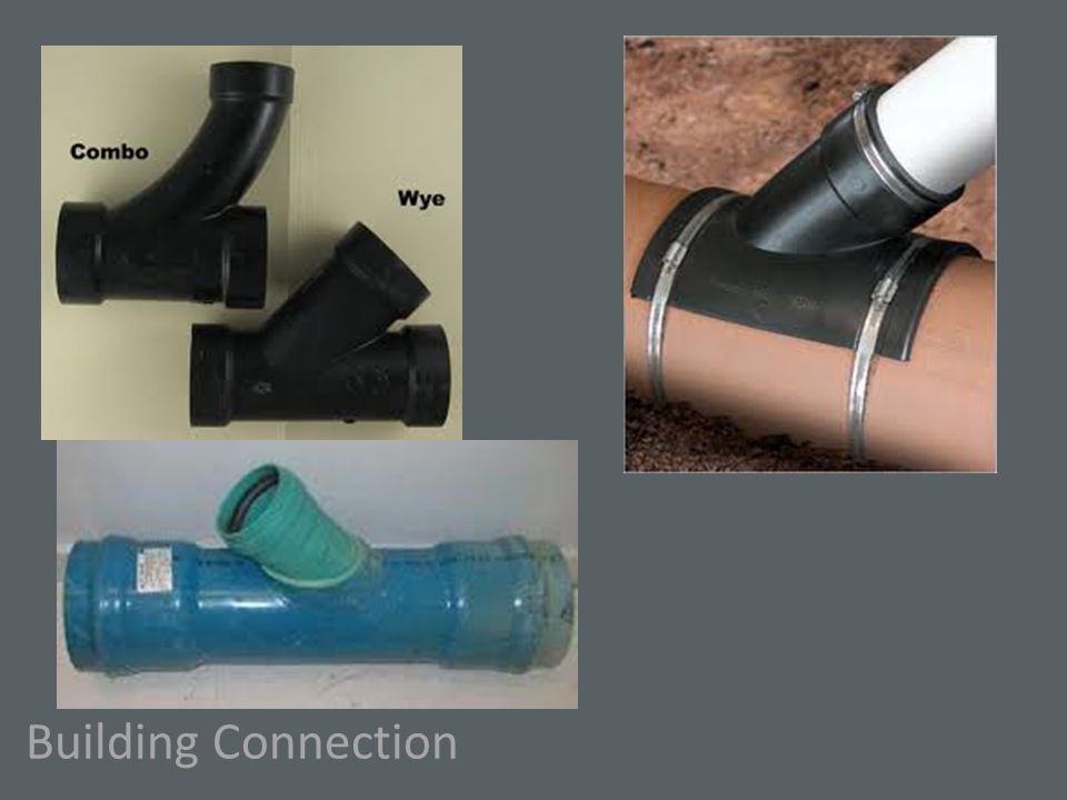
Building Connection

9
Sewer Alternatives Gravity Sewer Septic Tank Pumping Pressure Systems Vacuum Systems

10
Alternatives - STEP System

11
Alternatives – Pressure System

12
Alternatives - STEP System Centrifugal type Grinder Pump Curve

13
Alternatives – Pressure System

14
Pumping Rate (gpm) Discharge Head (ft) Moineau Type Pump Curve (e.g., E-One)
 Discharge Head (ft) Moineau Type Pump Curve (e.g., E-One)")
15
Alternatives – Vacuum System

16
http://www.roevac.com/page/ en/page_ID/42?PHPSESSID=d1 265aa3cfe97b116960cb0ce1d6 5499

17
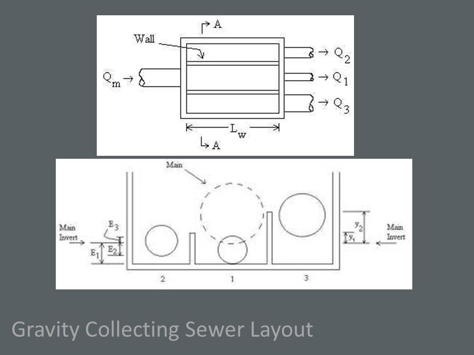
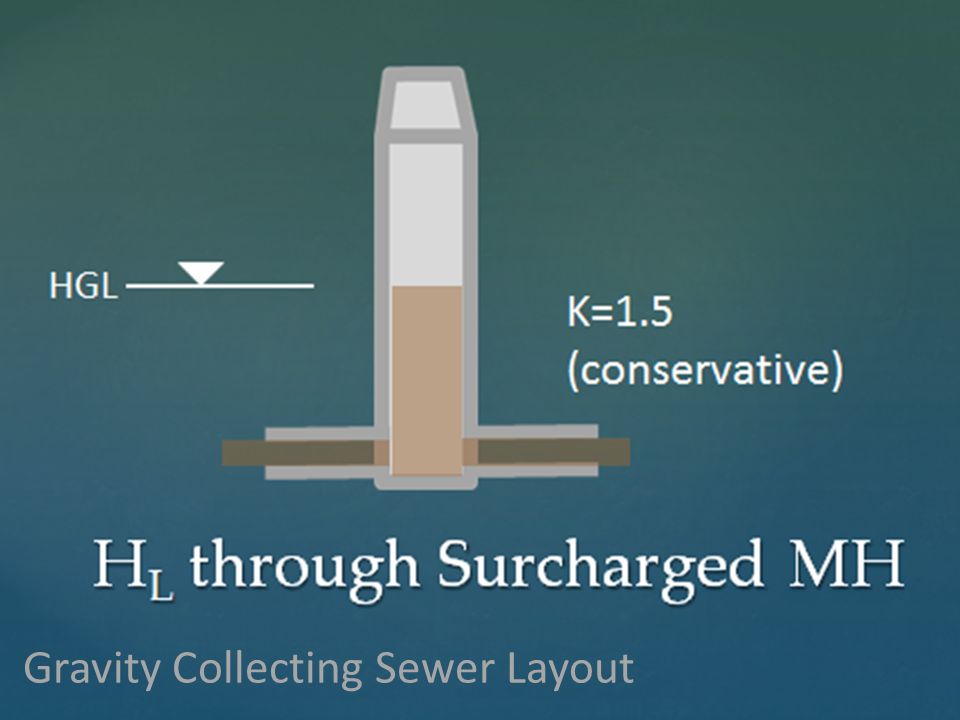
Gravity Collecting Sewer Layout Hypothetical Vertical Distances Required For Gravity Collector 9-12 ft 2.7-3.7 m S = 0.02

18
Gravity Collecting Sewer Layout

20
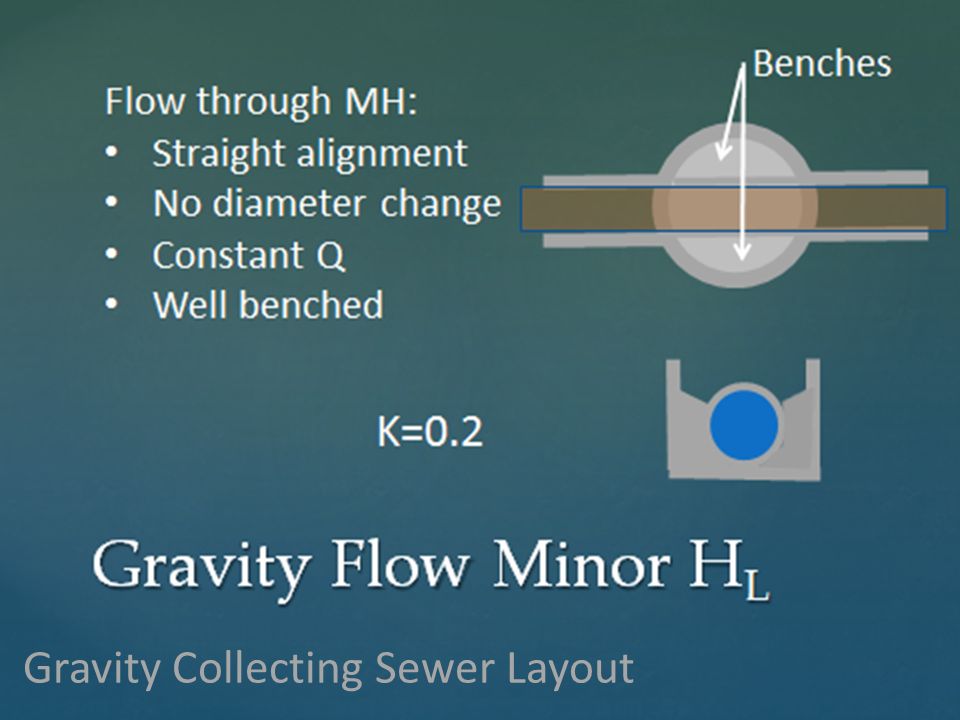
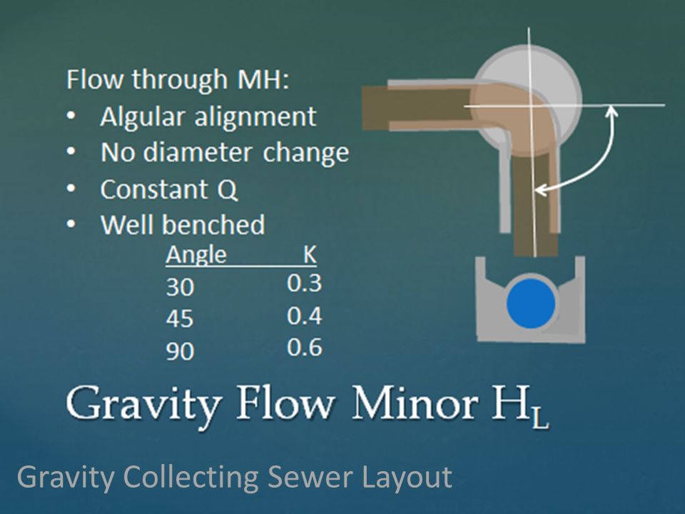
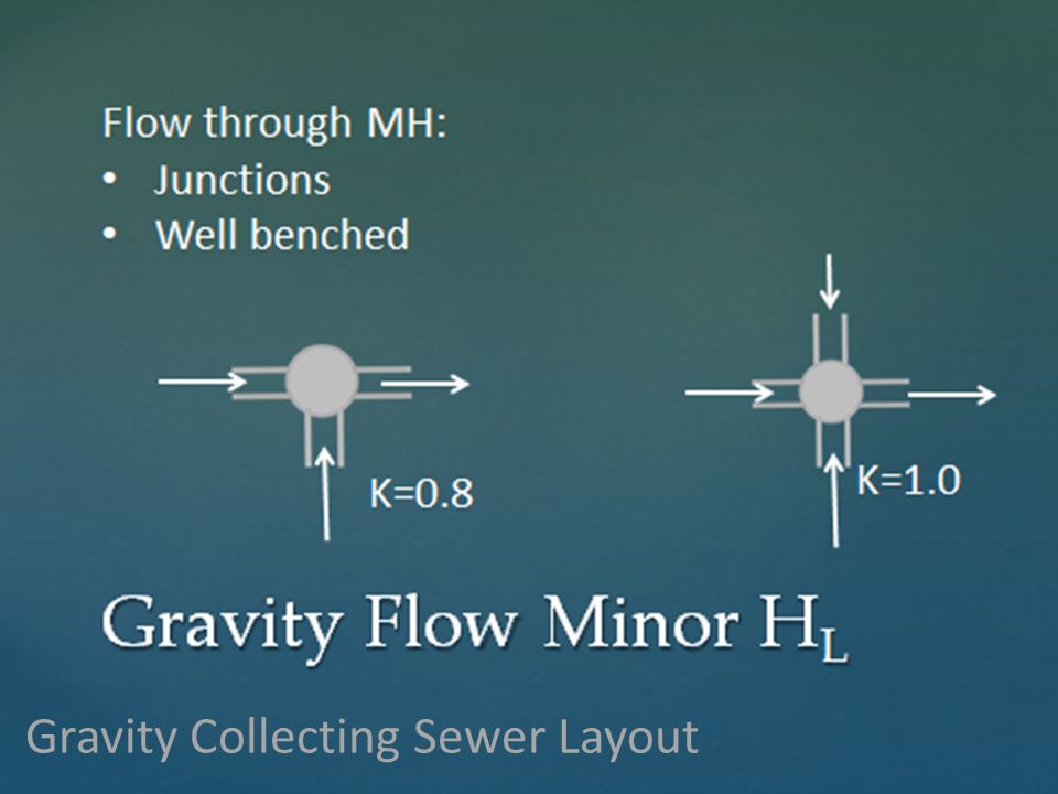
Manhole Requirements: At Upstream End of Sewer Where Connecting to Another Sewer At Change of Grade or Direction At Change of Size At Least Every 400 ft Normally no service connections

21
Gravity Collecting Sewer Layout 100 year flood + 1 ft Flood Proof MH Drop MH of > 2ft difference in elevation

22
Gravity Collecting Sewer Layout

24
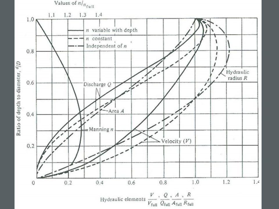
Hydraulics of Gravity Sewers Minimum velocity (self-cleansing velocity) = 0.6 m/s (2.0 ft/s) Maximum velocity = 3.5 m/s (11.5 ft/s) Minimum pipe diameter = 205 mm (8”) Sanitary sewers up to 375 mm diameter (15”) should be designed to run half full Larger pipes may run three-fourths full Manning’s “n” of 0.013-0.015 normally used Allow for minor losses at MHs
 = 0.6 m/s (2.0 ft/s) Maximum velocity = 3.5 m/s (11.5 ft/s) Minimum pipe diameter = 205 mm (8 ) Sanitary sewers up to 375 mm diameter (15 ) should be designed to run half full Larger pipes may run three-fourths full Manning’s n of normally used Allow for minor losses at MHs")
25
Gravity Collecting Sewer Layout Hydraulics of Gravity Sewers Minimum velocity (self-cleansing velocity) = 0.6 m/s (2.0 ft/s) Maximum velocity = 3.5 m/s (11.5 ft/s) Minimum pipe diameter = 205 mm (8”) Sanitary sewers up to 375 mm diameter (15”) should be designed to run half full Larger pipes may run three-fourths full Manning’s “n” of 0.013-0.015 normally used Allow for minor losses at MHs
 = 0.6 m/s (2.0 ft/s) Maximum velocity = 3.5 m/s (11.5 ft/s) Minimum pipe diameter = 205 mm (8 ) Sanitary sewers up to 375 mm diameter (15 ) should be designed to run half full Larger pipes may run three-fourths full Manning’s n of normally used Allow for minor losses at MHs")
26
Gravity Collecting Sewer Layout Hydraulics of Gravity Sewers Minimum velocity (self-cleansing velocity) = 0.6 m/s (2.0 ft/s) Maximum velocity = 3.5 m/s (11.5 ft/s) Minimum pipe diameter = 205 mm (8”) Sanitary sewers up to 375 mm diameter (15”) should be designed to run half full Larger pipes may run three-fourths full Manning’s “n” of 0.013-0.015 normally used Allow for minor losses at MHs
 = 0.6 m/s (2.0 ft/s) Maximum velocity = 3.5 m/s (11.5 ft/s) Minimum pipe diameter = 205 mm (8 ) Sanitary sewers up to 375 mm diameter (15 ) should be designed to run half full Larger pipes may run three-fourths full Manning’s n of normally used Allow for minor losses at MHs")
27
Gravity Collecting Sewer Layout Hydraulics of Gravity Sewers Minimum velocity (self-cleansing velocity) = 0.6 m/s (2.0 ft/s) Maximum velocity = 3.5 m/s (11.5 ft/s) Minimum pipe diameter = 205 mm (8”) Sanitary sewers up to 375 mm diameter (15”) should be designed to run half full Larger pipes may run three-fourths full Manning’s “n” of 0.013-0.015 normally used Allow for minor losses at MHs
 = 0.6 m/s (2.0 ft/s) Maximum velocity = 3.5 m/s (11.5 ft/s) Minimum pipe diameter = 205 mm (8 ) Sanitary sewers up to 375 mm diameter (15 ) should be designed to run half full Larger pipes may run three-fourths full Manning’s n of normally used Allow for minor losses at MHs")
28
Gravity Collecting Sewer Layout Hydraulics of Gravity Sewers Minimum velocity (self-cleansing velocity) = 0.6 m/s (2.0 ft/s) Maximum velocity = 3.5 m/s (11.5 ft/s) Minimum pipe diameter = 205 mm (8”) Sanitary sewers up to 375 mm diameter (15”) should be designed to run half full Larger pipes may run three-fourths full Manning’s “n” of 0.013-0.015 normally used Allow for minor losses at MHs
 = 0.6 m/s (2.0 ft/s) Maximum velocity = 3.5 m/s (11.5 ft/s) Minimum pipe diameter = 205 mm (8 ) Sanitary sewers up to 375 mm diameter (15 ) should be designed to run half full Larger pipes may run three-fourths full Manning’s n of normally used Allow for minor losses at MHs")
29
Gravity Collecting Sewer Layout Hydraulics of Gravity Sewers Minimum velocity (self-cleansing velocity) = 0.6 m/s (2.0 ft/s) Maximum velocity = 3.5 m/s (11.5 ft/s) Minimum pipe diameter = 205 mm (8”) Sanitary sewers up to 375 mm diameter (15”) should be designed to run half full Larger pipes may run three-fourths full Manning’s “n” of 0.013-0.015 normally used Allow for minor losses at MHs
 = 0.6 m/s (2.0 ft/s) Maximum velocity = 3.5 m/s (11.5 ft/s) Minimum pipe diameter = 205 mm (8 ) Sanitary sewers up to 375 mm diameter (15 ) should be designed to run half full Larger pipes may run three-fourths full Manning’s n of normally used Allow for minor losses at MHs")
30
Gravity Collecting Sewer Layout Hydraulics of Gravity Sewers Minimum velocity (self-cleansing velocity) = 0.6 m/s (2.0 ft/s) Maximum velocity = 3.5 m/s (11.5 ft/s) Minimum pipe diameter = 205 mm (8”) Sanitary sewers up to 375 mm diameter (15”) should be designed to run half full Larger pipes may run three-fourths full Manning’s “n” of 0.013-0.015 normally used Allow for minor losses at MHs
 = 0.6 m/s (2.0 ft/s) Maximum velocity = 3.5 m/s (11.5 ft/s) Minimum pipe diameter = 205 mm (8 ) Sanitary sewers up to 375 mm diameter (15 ) should be designed to run half full Larger pipes may run three-fourths full Manning’s n of normally used Allow for minor losses at MHs")
31
Regulations will specify minimum slope From WI NR 110.13 Gravity Collecting Sewer Layout

32
Regulations will specify minimum slope From WI NR 110.13 Gravity Collecting Sewer Layout Use greater slope if possible.

33
Use Hydraulic Elements Table or Chart Gravity Collecting Sewer Layout

35
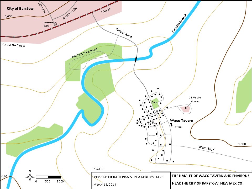
Layout of collection network makes advantage of topography Gravity Collecting Sewer Layout

36
Layout of collection network makes advantage of topography Gravity Collecting Sewer Layout Normally locate in Public ROW Access for Maintenance

37
Alternative approach using back yards Gravity Collecting Sewer Layout

38
Alternative approach using back yards Gravity Collecting Sewer Layout Difficult physical access for maintenance Easement-Access issues Landowners may build over sewer

39
Alternative approach using back yards Gravity Collecting Sewer Layout

44
Drop Sewer used for > 2 ft difference in invert elevations

45
Gravity Collecting Sewer Layout When diameter increases, match at crowns or 0.8 depth

46
Gravity Collecting Sewer Layout When diameter increases, match at crowns or 0.8 depth 0.8 D u 0.8 D D

48
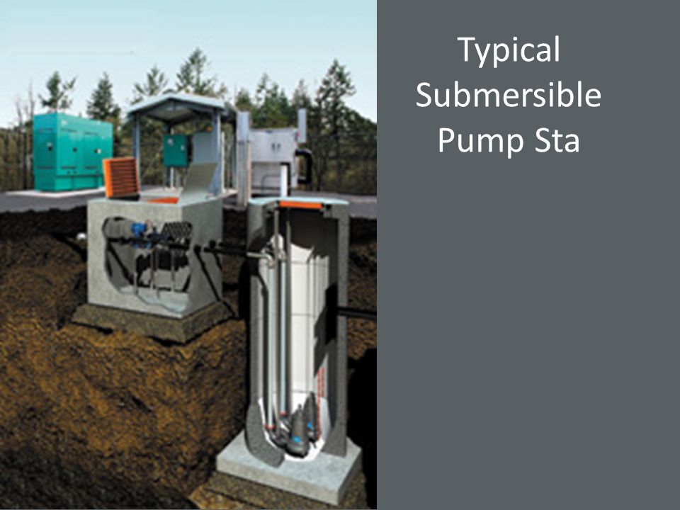
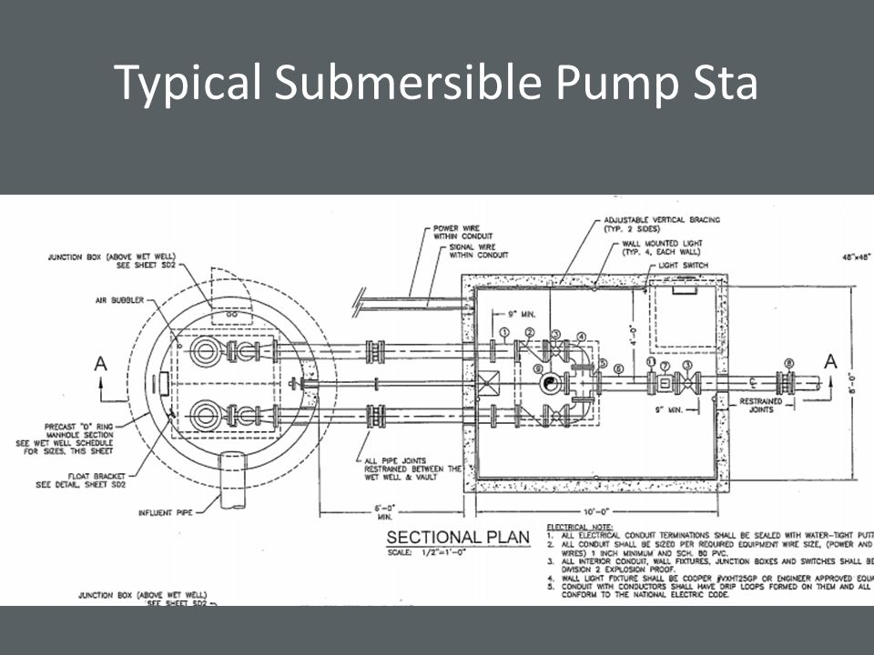
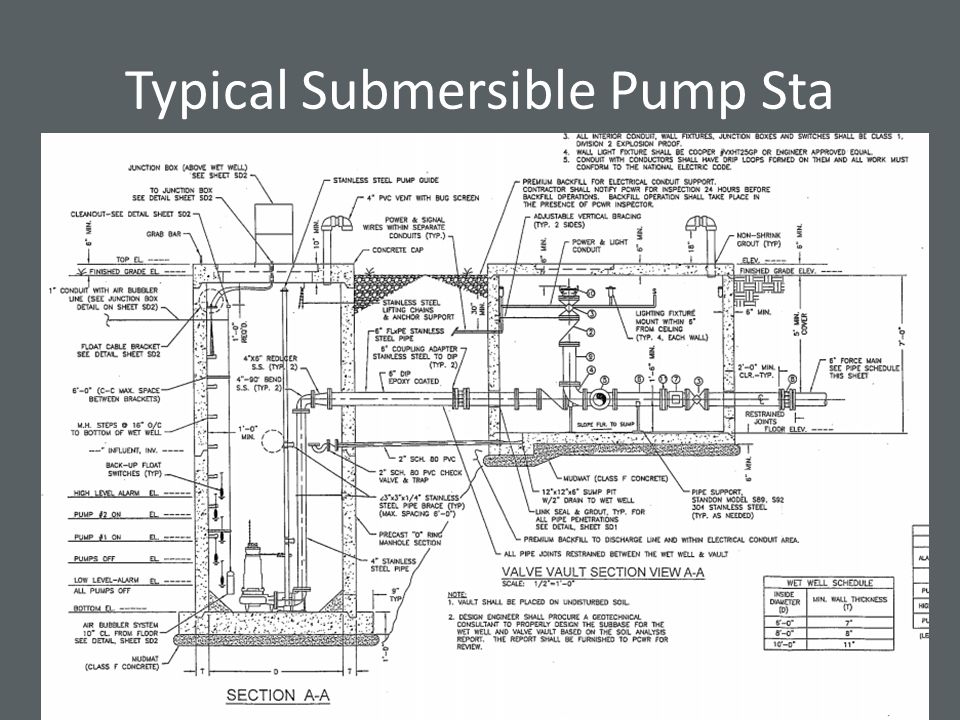
Typical Submersible Pump Sta

54
1A 1B 1C 1D 1E 1F 1G 1H 1I 1K 1L 11A 11B 11C 111A 111B 11D 1111A 1111B 111C 12A 12B 12C 12E 12D 121A 121B 122B 122A 123A 123B Branch MH Numbering Scheme

55
A B C D 123

56
A2a

Similar presentations


. Sewer Basics Collection and transport of wastewater from each home/building to the point where treatment occurs.>")


>")


 Below you see a cross-section of a ditch. It runs parallel to a 200-acre field consisting of permanent pasture.>")


![Assignment No. 1 [Grup 8] Figure below shows a portion of a hydraulic circuit. The pressure point B must be 200 psig when the volume flow rate is 60 gal/min.](/20/6053192/big_thumb.jpg "Assignment No. 1 [Grup 8] Figure below shows a portion of a hydraulic circuit. The pressure point B must be 200 psig when the volume flow rate is 60 gal/min.>")