Download presentation
Presentation is loading. Please wait.

1
Chapter 9 Memory Organization

2
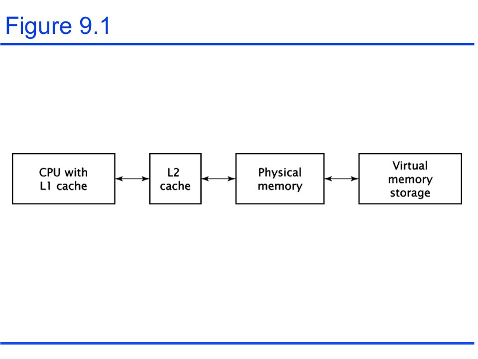
9.1 Hierarchical Memory Systems Figure 9.1

4
9.2 Cache Memory Associative memory (or CAM: Contents Addressable Memory) Figure 9.2 –Valid bit –Argument(or data): data register –Mask(or key): mask register –Match: match register –Output register
 Figure 9.2 –Valid bit –Argument(or data): data register –Mask(or key): mask register –Match: match register –Output register")
5
Figure 9.2

6
Cache memory with associative mapping Associative cache: cache with associative mapping (Figure 9.3) –Lines or blocks of data (Figure 9.4) Locality of reference –Spatial locality –Temporal locality –Sequentiality
 –Lines or blocks of data (Figure 9.4) Locality of reference –Spatial locality –Temporal locality –Sequentiality")
7
Figure 9.3

8
Figure 9.4

9
Cache memory with direct mapping Index: to select one specific location in the cache. (low-order address bits) Tag(the high-order bits of original address which were not a part of the index) Figure 9.5 Direct-mapped cache allows for lines of data. (Figure 9.6) The direct-mapped cache is much less expensive than the associative cache, but also much less flexible.
 Tag(the high-order bits of original address which were not a part of the index) Figure 9.5 Direct-mapped cache allows for lines of data. (Figure 9.6) The direct-mapped cache is much less expensive than the associative cache, but also much less flexible..")
10
Figure 9.5

11
Figure 9.6

12
Cache memory with set- associative mapping N-way set-associative cache Two-way set-associative cache: Figure 9.7 Two-way set-associative cache with 4 bytes of data per line: Figure 9.8

13
Figure 9.7

14
Figure 9.8

15
Replacing data in the cache Direct mapping offers the easiest solution to the replacement problem. The associative cache allows any location in the physical memory to be mapped to any location in cache. Three typical replacement strategies are –FIFO –LRU –Random The set-associative cache also needs replacement strategy. (Figure 9.9)
.")
16
Figure 9.9

17
Writing data to the cache Write-through Write-back

18
Cache performance Cache hits and cache misses Hit ratio Average memory access time Where Tc: cache access time, Tp:memory access time, h: hit ratio Refer to Table 9.1,9.2,9.3,9.4,9.5,9.6 and 9.7

19
9.8 Virtual Memory Most advanced CPUs can address more memory location than physical memory space. virtual memory –MMU – swap disk or swap file –Logical address –Physical memory address

20
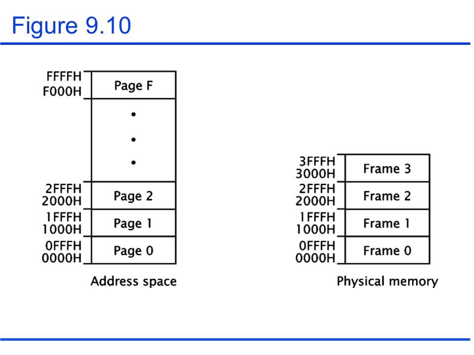
Paging Pages Frames Figure 9.10

22
Issues of paging When should a page be moved into physical memory? How does the CPU find data in physical memory, if its logical address is not same as its physical address? What happens when all the frames have pages and the CPU needs to access data from a page not currently stored in physical memory?

23
Issues of paging(continued) The MMU handles all of these issues. –Page fault –Page table –Valid bit –Offset –Demand paging –TLB Figure 9.11, 9.12, and 9.13

24
Figure 9.11

25
Figure 9.12

26
Figure 9.13

27
Figure 9.14

28
Segmentation Segments Internal fragmentation External fragmentation Figure 9.15and 9.16 Combining a segmentation and paging (Figure 9.17)
")
29
Figure 9.15

30
Figure 9.16

31
Figure 9.17

32
Memory protection Protection bits Supervisor or kernel mode

33
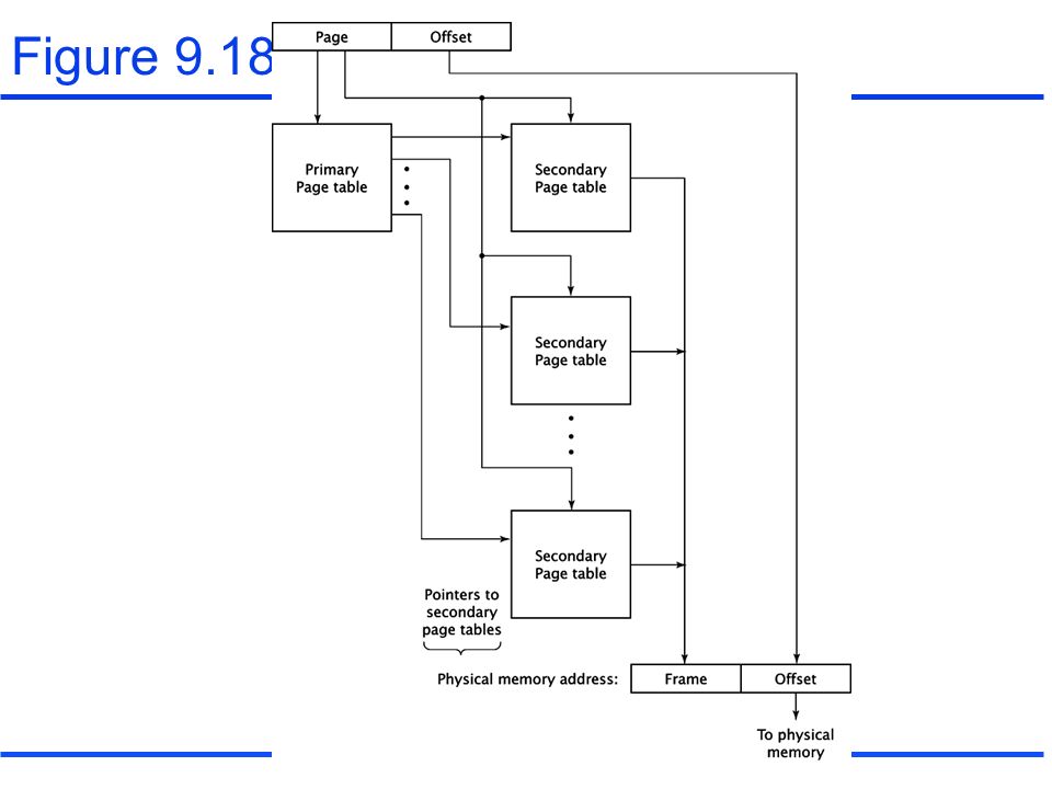
Multiple page table Figure 9.18

35
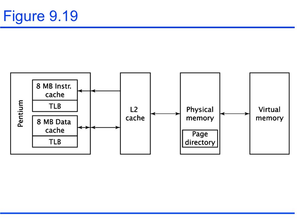
Memory management in a Pentium/Windows PC Figure 9.19

Similar presentations


 storage l Managed jointly by CPU hardware.>")


 Cache memories.>")


 (Caches, Main Memory and.>")

