Download presentation
Presentation is loading. Please wait.

1
11/12/20151 Status of high intensity polarized electron gun project at MIT-Bates Evgeni Tsentalovich MIT

2
General Information Polarized electron guns utilize GaAs photo cathodes. When polarized laser beam strikes the cathode, polarized electrons are ejected. Photocathodes must have atomically clean surface and they must be activated by heating to about 600°C and applying Cs and NF3 to the surface. UHV conditions are required in the gun. Any traces of gases (excluding hydrogen and noble gases) poison the crystal.
 poison the crystal..")
3
09/11/20133 eRHIC (Linac-ring version) Requires a polarized electron source with an extremely high current ( at least 10 mA). Modern state-of-the-art guns produce ~100-200 A Average current of ~ 1 mA achieved in tests at JLab and Mainz; Average current of up to 10 mA achieved at Mainz with very short lifetime (needs active cathode cooling) Main problem – ion back bombardment. Anode hole acts like a focusing lens for ions. Ion damage is most severe at the center of the cathode.
 Main problem – ion back bombardment. Anode hole acts like a focusing lens for ions. Ion damage is most severe at the center of the cathode..")
4
09/11/20134 Ion damage mostly the center of cathode (Bates results) Laser beam profile Damage pattern
 Laser beam profile Damage pattern")
5
High Intensity Polarized Electron Gun The principal points to achieve high average current: Large area cathode. Ions tend to damage the central area of the cathode – ring-shaped emission pattern. Active cathode cooling. Very small beam losses could be allowed near the gun ( ).
..")
6
Additional requirements Heat-cleaning and activation compromise vacuum condition, they should be done in a separate chamber (preparation chamber). It takes months to achieve good vacuum, so gun chamber and preparation chamber should never be vented. New cathodes should be loaded into the system via load lock.

7
Cathode cooling (Fluorinert) Cathode puck (Moly) Heat exchanger
 Cathode puck (Moly) Heat exchanger")
8
Cathode – anode assembly Fluorinert (cooling agent)
")
9
Cathode – anode assembly Fluorinert (cooling agent)
")
10
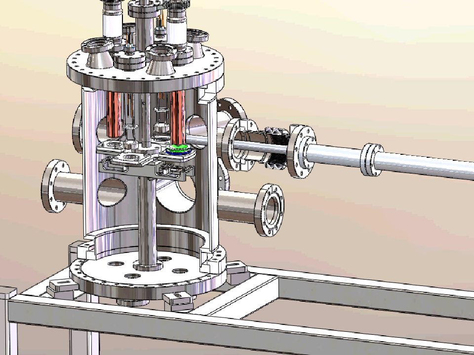
Gun chamber

11
Preparation chamber

12
Load lock

16
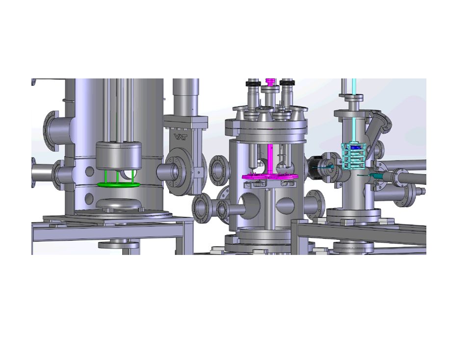
Gun + beam line

17
Beam line. Pipe aperture ~±34 mm. Gun Dipoles Solenoidal lenses Beam dump

18
Gun + beam line

19
Gun chamber

20
Prep. chamber

21
Vacuum features of the chambers Gun chamber: 100 l/s Ion pump with 400 l/s NEG and 4 additional 400 l/s NEGs. The chamber walls are thin (~ 3 mm) to reduce outgasing. The chamber and most of the parts have been prebaked to 400°C before the final assembly. Bake-out at 250°C after the final assembly. Vacuum ~ (all Hydrogen) Prep. chamber: 100 l/s Ion pump with 400 l/s NEG and 2 additional 400 l/s NEGs. Vacuum ~ (all Hydrogen)
 to reduce outgasing. The chamber and most of the parts have been prebaked to 400°C before the final assembly. Bake-out at 250°C after the final assembly. Vacuum ~ (all Hydrogen) Prep. chamber: 100 l/s Ion pump with 400 l/s NEG and 2 additional 400 l/s NEGs. Vacuum ~ (all Hydrogen).")
22
BUDGET FYFrom BNLFrom DOEActual cost to date 07-09$444 K 10-11$150 K$586 K$736 K 12-13$388 K 14-15$500 K$197 K Total$594 K$1474 K$1765 K

23
PROJECT PROGRESS FY 2007-2009 - preliminary simulations and tests. Beam simulations through the gun and entire beam line. Emphasis – no beam losses near the gun. Tests of active cooling. HV tests. FY 2010-2011 – gun chamber and preparation chamber built and assembled. Load lock and beam line designed, and manufacturing began. FY 2012-2013 – load lock build and assembled. Beam line and unbiased beam dump built. FY2014-2015 – beam line and beam dump completed. First beam tests.

24
PROJECT PROBLEMS Gun chamber, preparation chamber, load lock manufacturing and assembly – not a glitch. Excellent vacuum conditions. Reliable cathode transfer between chambers (good illumination and observation conditions). Very high QE (~2% at λ=805 nm) has been achieved. However, the dark lifetime of the cathode in the gun is short (less than 100 hours). Beam line assembly – successful. Beam tuning through the beam line – the shape of the beam in a full agreement with simulations. Beam dump bake out – first problem. The solder in the assembly melted venting the chamber. Lost NEG. Tight budget makes such accidents time consuming (delivery time 6 weeks). Beam tests – real problem. The lifetime is much shorter than in old generation guns even at low current.
. Very high QE (~2% at λ=805 nm) has been achieved. However, the dark lifetime of the cathode in the gun is short (less than 100 hours). Beam line assembly – successful. Beam tuning through the beam line – the shape of the beam in a full agreement with simulations. Beam dump bake out – first problem. The solder in the assembly melted venting the chamber. Lost NEG. Tight budget makes such accidents time consuming (delivery time 6 weeks). Beam tests – real problem. The lifetime is much shorter than in old generation guns even at low current..")
25
Beam on BeO target

26
SECOND TRY Most likely the problem is a fluorinert leak into the gun chamber. The molecules ar very compact and penetrate through very narrow cracks, they are too heavy to be detected with RGA, and they are chemically active. The gun was vented and the problem addressed. Preparation chamber was vented as well to fix minor problems. Reassembly and rebake. A whole bunch of accidents: Gasket failure during bake out (twice) Magnetic manipulator support system putting pressure on the gasket during alignment, causing leak and venting both gun and preparation chamber Ceramic support standoff for Cs strips creaked shortening the strips to the ground (another 6 weeks delivery item).
 Magnetic manipulator support system putting pressure on the gasket during alignment, causing leak and venting both gun and preparation chamber Ceramic support standoff for Cs strips creaked shortening the strips to the ground (another 6 weeks delivery item)..")
27
CURRENT STATUS After all those problems have been solved, a fresh cathode was activated and transferred into the gun chamber for dark lifetime measurements. The dark lifetime (was less than 100 hours) has increased to almost infinity ( at least tens of thousands hours). Whatever decease the gun had is gone. The section of the beam line vented previously was rebaked last week. We still need to reinstall all magnetic elements (dipoles, steering coils) and magnetic shielding. We plan to resume beam tests in 2 weeks.
 has increased to almost infinity ( at least tens of thousands hours). Whatever decease the gun had is gone. The section of the beam line vented previously was rebaked last week. We still need to reinstall all magnetic elements (dipoles, steering coils) and magnetic shielding. We plan to resume beam tests in 2 weeks..")
Similar presentations


 M. Yamamoto, T. Miyajima, Y. Honda KEK H. Iijima, M.>")


>")


