Download presentation
Presentation is loading. Please wait.

1
Goal: 10 -29 e cm and with an upgrade (stochastic cooling,…) can reach 10 -30 e cm R&D: 1) SQUID-based BPMs, 2) Polarimeter, 3) Precision tracking/SCT, 4) E-field tests Staging: <10 -27 e cm; <10 -29 e cm; <10 -30 e cm Snowmass on the Mississippi Minneapolis, July 31, 2013 Intro to Storage Ring EDMs and proton EDM experiment Yannis Semertzidis, BNL
 can reach e cm R&D: 1) SQUID-based BPMs, 2) Polarimeter, 3) Precision tracking/SCT, 4) E-field tests Staging: < e cm; < e cm; < e cm Snowmass on the Mississippi Minneapolis, July 31, 2013 Intro to Storage Ring EDMs and proton EDM experiment Yannis Semertzidis, BNL")
4
Colloquium questions related to EDM IF19. If the LHC does not discover new physics, what can be learned from more precise measurements in the quark flavor sector? What level of precision is desirable for neutron/proton, electron and atomic EDM experiments in this scenario? What if LHC does find New Physics?

5
Physics of EDM of fundamental particles. Proton EDM: >10 3 TeV for SUSY-like New Physics Nima Arkani-Hamed, Intensity Frontier, Rockville, 2011

6
Electroweak Baryogenises GUT SUSY J.M.Pendlebury and E.A. Hinds, NIMA 440 (2000) 471 e-cm Gray: Neutron Red: Electron n current n target Sensitivity to Rule on Several New Models e current e target p, d target If found it could explain Baryogenesis If found it could explain Baryogenesis pEDM experiment complementary to LHC pEDM experiment complementary to LHC Statistics limited Upgrade?
 471 e-cm Gray: Neutron Red: Electron n current n target Sensitivity to Rule on Several New Models e current e target p, d target If found it could explain Baryogenesis If found it could explain Baryogenesis pEDM experiment complementary to LHC pEDM experiment complementary to LHC Statistics limited Upgrade .")
7
EDMs of different systems Theta_QCD: Super-Symmetry (SUSY) model predictions: Measure all three: proton, deuteron and neutron EDMs to determine CPV source
 model predictions: Measure all three: proton, deuteron and neutron EDMs to determine CPV source")
8
Physics reach of magic pEDM (Marciano) The proton EDM at 10 -29 e∙cm has a reach of >300TeV or, if new physics exists at the LHC scale, <10 -7 -10 -6 rad CP-violating phase; an unprecedented sensitivity level. The deuteron EDM sensitivity is similar. Sensitivity to SUSY-type new Physics: Sensitivity to new contact interaction: 3000 TeV

9
A balanced approach is best…!

10
G. Isidori at ESPP Open Symposium, Cracow (Sept. 2012) Physics: Potential of EDMs 10
 Physics: Potential of EDMs 10")
11
For particles with intrinsic angular momentum (spin S): In a magnetic field (B), there is a torque:
: In a magnetic field (B), there is a torque:")
12
For particles with an EDM along the spin: In an Electric field (E), there is a torque:
, there is a torque:")
13
- p. 13/28 Phys. Rev. 78 (1950) Purcell and Ramsey: “ The question of the possible existence of an electric dipole moment of a nucleus or of an elementary particle…becomes a purely experimental matter”
 Purcell and Ramsey: The question of the possible existence of an electric dipole moment of a nucleus or of an elementary particle…becomes a purely experimental matter .")
14
A charged particle between Electric Field plates would be lost right away… - + + So work on the EDM starts with the neutron and neutral atoms (e - )
")
15
Measuring an EDM of Neutral Particles H = -(d E + μ B) ● I/I m I = 1/2 m I = -1/2 ω1ω1 ω2ω2 d EB µ d µ EB d = 10 -28 e cm E = 200 kV/cm = 10 -7 rad/s ~1 turn/year
 ● I/I m I = 1/2 m I = -1/2 ω1ω1 ω2ω2 d EB µ d µ EB d = e cm E = 200 kV/cm = rad/s ~1 turn/year ")
16
EDM Experimental Issues 1.Statistics (~1-10 n/cm 3 ) 2.Magnetic fields can mimic EDM signal (need to measure B-fields acting on the particles) 3.Geometrical phase: spin rotations in three dimensions don’t commute.
 2.Magnetic fields can mimic EDM signal (need to measure B-fields acting on the particles) 3.Geometrical phase: spin rotations in three dimensions don’t commute.")
17
Charged particles in a Storage Ring! Position is determined by the fields

18
Clock-wise (CW) & Counter-Clock-wise Storage Any radial magnetic field sensed by the stored particles will also cause their vertical splitting. Electric storage ring

19
Comparing Methods Neutrons in a box have an advantage: no electric force, small volumes Protons in a storage ring: 1.Primary source, revolution in statistics 2.Position displacement sensitive to background magnetic fields 3.Geometrical phase: EDM-like signal depends on azimuthal location; position displacement

20
Short History of EDM 1950’s neutron EDM experiment started to search for parity violation (Ramsey and Purcell). After P-violation EDMs require both P,T-Violation 1960’s EDM searches in atomic systems 1970’s Indirect Storage Ring EDM method from the CERN muon g-2 exp. 1980’s Theory studies on systems (molecules) w/ large enhancement factors 1990’s First exp. attempts w/ molecules. Dedicated Storage Ring EDM method developed for muons. 2000’s Proposal for sensitive dEDM exp. developed. 2010’s Proposal for sensitive pEDM exp. developed.
 w/ large enhancement factors 1990’s First exp. attempts w/ molecules. Dedicated Storage Ring EDM method developed for muons. 2000’s Proposal for sensitive dEDM exp. developed. 2010’s Proposal for sensitive pEDM exp. developed..")
21
We have developed the Storage Ring EDM Method: (http://www.bnl.gov/edm) Muon EDM sensitivity 10 -24 e cm Proton EDM sensitivity 10 -29 e cm 10 -30 e cm Deuteron EDM sensitivity 10 -29 e cm Under develop.: eEDM pre-cursor exp.: 10 -27 ? 3 He (~neutron equivalent), …p, d, n EDMs are needed to decipher the CP-violation source…
, …p, d, n EDMs are needed to decipher the CP-violation source….")
22
Physics strength comparison (Marciano) SystemCurrent limit [e cm] Future goalNeutron equivalent Neutron<1.6×10 -26 ~10 -28 10 -28 199 Hg atom<3×10 -29 10 -25 -10 -26 129 Xe atom<6×10 -27 ~10 -30 -10 -33 10 -26 -10 -29 Deuteron nucleus ~10 -29 3×10 -29 - 5×10 -31 Proton nucleus <7×10 -25 ~10 -29 -10 -30 10 -29 -10 -30
![Physics strength comparison (Marciano) SystemCurrent limit [e cm] Future goalNeutron equivalent Neutron<1.6× ~ Hg atom<3× Xe atom<6× ~ Deuteron nucleus ~ × × Proton nucleus <7× ~](http://images.slideplayer.com/36/10672325/slides/slide_22.jpg "Physics strength comparison (Marciano) SystemCurrent limit [e cm] Future goalNeutron equivalent Neutron<1.6× ~ Hg atom<3× Xe atom<6× ~ Deuteron nucleus ~ × × Proton nucleus <7× ~")
23
Storage Ring Proton EDM Method Precision physics in storage rings

24
Yannis Semertzidis, BNL Muon g-2: Precision physics in a Storage Ring Statistics limited… to improve sensitivity by a factor of 4 at Fermilab

25
Yannis Semertzidis, BNL Muon g-2: 4 Billion e + with E>2GeV Sub-ppm accuracy, statistics limited

26
Breakthrough concept: Freezing the horizontal spin precession due to E-field Muon g-2 focusing is electric: The spin precession due to E-field is zero at “magic” momentum (3.1GeV/c for muons, 0.7 GeV/c for protons,…) The “magic” momentum concept was used in the muon g-2 experiments at CERN, BNL, and …now at FNAL.
 The magic momentum concept was used in the muon g-2 experiments at CERN, BNL, and …now at FNAL.")
27
Yannis Semertzidis, BNL B Ron McNabb’s Thesis 2003: x y z s β Indirect Muon EDM limit from the g-2 Experiment

28
Yannis Semertzidis, BNL The proton EDM uses an ALL-ELECTRIC ring: spin is aligned with the momentum vector Momentum vector Spin vector E E E E At the magic momentum the spin and momentum vectors precess at same rate in an E-field. Similar to muon g-2 method.

29
proton EDM proposal to DOE NP: November 2011 Weak vertical focusing to optimize SCT and BPM operation B: quadrupoles Lattice: R. Talman

30
Extraction: lowering the vertical focusing strength “defining aperture” polarimeter target carries EDM signal increases slowly with time carries in-plane (g-2) precession signal pEDM polarimeter principle (placed in a straight section of the ring): probing the proton spin components as a function of storage time Micro-Megas TPC detector and/or MRPC
 precession signal pEDM polarimeter principle (placed in a straight section of the ring): probing the proton spin components as a function of storage time Micro-Megas TPC detector and/or MRPC")
31
(L-R)/(L+R) vs. Time [s] M.C. data The EDM signal: early to late change Comparing the (left-right)/(left+right) counts vs. time we monitor the vertical component of spin Signal is max when ω a ~0
![(L-R)/(L+R) vs. Time [s] M.C.](http://images.slideplayer.com/36/10672325/slides/slide_31.jpg "data The EDM signal: early to late change Comparing the (left-right)/(left+right) counts vs. time we monitor the vertical component of spin Signal is max when ω a ~0.")
32
The polarimeter analyzing power at P magic is very large Analyzing power can be further optimized

33
Proton beam parameters Counter-Rot. P-beams 0.7 GeV/c, 233 MeV 80% polariz.; ~4×10 10 protons/store <200ns base length Repetition period: 20 minutes Beam energy: ~1J Average beam power: ~1mW Beam emittance: 95%, norm. Horizontal: 2 mm- mrad Vertical: 6 mm-mrad (dp/p) rms ~ 2×10 -4 CW & CCW injections. One RF-cavity. Beam parameters can be presently available at BNL; need to duplicate at FNAL (pol. protons, etc.)
 rms ~ 2×10 -4 CW & CCW injections. One RF-cavity. Beam parameters can be presently available at BNL; need to duplicate at FNAL (pol. protons, etc.).")
34
The current status Have developed R&D plans for 1) BPM magnetometers (need to test in rings) 2) SCT tests at COSY (benchmark estimations) 3) E-field development (first phase R&D done) 4) Polarimeter prototype (first phase R&D done) 5) Simulation/tracking (great progress) We had two successful technical reviews: Dec 2009, and March 2011. Proposal to DOE NP for proton EDM at BNL: November 2011; LOI to FNAL: October 2012 34

35
International srEDM Network Common R&D srEDM Coll. pEDM Proposal to DOE NP EOI to FNAL SQUID-based BPMs tests at RHIC Precision simulation Systematic error studies E-field tests … JEDI (COSY/Jülich) Ring design EDM at COSY Polarimeter tests Spin Coherence Time tests Precision simulation Cooling E-field tests …
 Ring design EDM at COSY Polarimeter tests Spin Coherence Time tests Precision simulation Cooling E-field tests ….")
36
R&D progress

37
Two storage ring projects being pursued (from R. Talman) (from A. Lehrach) 37 USA: protons all-electric machine Jülich, focus on deuterons, or a combined machine CW and CCW stored beams
 37 USA: protons all-electric machine Jülich, focus on deuterons, or a combined machine CW and CCW stored beams.")
38
Experiment Parameters (proposal) 1.Proton magic momentum: 0.7 GeV/c (233 MeV kinetic) 2.E = 10.5 MV/m for 3 cm plate separation 3.R = 40 m; plus straight sections 4.Weak vertical focusing: vertical tune 0.2 0.1 5.Stored particles: ~10 10 per 10 3 s, 10 4 injections
 1.Proton magic momentum: 0.7 GeV/c (233 MeV kinetic) 2.E = 10.5 MV/m for 3 cm plate separation 3.R = 40 m; plus straight sections 4.Weak vertical focusing: vertical tune 0.2 Stored particles: ~10 10 per 10 3 s, 10 4 injections")
39
What makes the pEDM experiment 1.Magic momentum (MM): high intensity charged beam in an all-electric storage ring 2.High analyzing power: A>50% at the MM 3.Weak vertical focusing in an all-electric ring: SCT allows for 10 3 s beneficial storage; prospects for much longer SCT with mixing (cooling and heating, smaller dp/p) 4.The beam vertical position tells the average radial B-field; the main systematic error source 5.Geometrical-phase specs: 0.1mm
: high intensity charged beam in an all-electric storage ring 2.High analyzing power: A>50% at the MM 3.Weak vertical focusing in an all-electric ring: SCT allows for 10 3 s beneficial storage; prospects for much longer SCT with mixing (cooling and heating, smaller dp/p) 4.The beam vertical position tells the average radial B-field; the main systematic error source 5.Geometrical-phase specs: 0.1mm")
40
1. SQUID-Based BPM The beam separation depends on the strength of the vertical tune: plan for 0.1 Modulate vertical tune by ~10% at 10 3 -10 4 Hz This creates a radial B-field at 10 3 -10 4 Hz to be picked up by a SQUID

41
D. Kawall Modulation frequency range

42
2. Polarimeter Development Polarimeter tests with runs at COSY (Jülich/Germany) demonstrated < 1ppm level systematic errors: N. Brantjes et al., NIM A 664, 49, (2012) Technologies under investigation: 1.Micro-Megas/Greece: high rate, pointing capabilities, part of R&D for ATLAS upgrade 2.MRPC/Italy: high energy resolution, high rate capability, part of ALICE development
 demonstrated < 1ppm level systematic errors: N. Brantjes et al., NIM A 664, 49, (2012) Technologies under investigation: 1.Micro-Megas/Greece: high rate, pointing capabilities, part of R&D for ATLAS upgrade 2.MRPC/Italy: high energy resolution, high rate capability, part of ALICE development.")
43
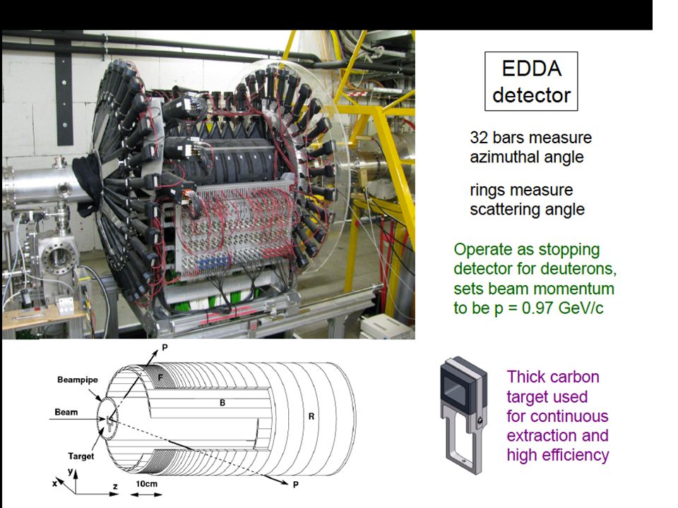
Storage Ring EDM Technical Review – 12/7/2009 4 Polarimeter Development COSY ring: Use EDDA detector COSY in Jülich/Germany tests EDDA detector: Rings and bars to determine angles. LEFT UP DOWNRIGHT Azimuthal angles yield two asymmetries: E. Stephenson, Indiana University

44
3. Spin Coherence Time: need >10 2 s Not all particles have same deviation from magic momentum, or same horizontal and vertical divergence (all second order effects) They cause a spread in the g-2 frequencies: Present design parameters allow for 10 3 s store Cooling/mixing during storage could prolong SCT (upgrade option).
 They cause a spread in the g-2 frequencies: Present design parameters allow for 10 3 s store Cooling/mixing during storage could prolong SCT (upgrade option)..")
45
Vert. tune =.1 Vertical oscillations Horizontal oscillations Horizontal Oscill. dp/p With RF-cavity ON

46
46 4. Large Scale Electrodes, New: pEDM electrodes with HPWR ParameterTevatron pbar-p Separators BNL K-pi Separators pEDM Length2.6m4.5m3m Gap5cm10cm3cm Height0.2m0.4m0.2m Number24210 2 Max. HV 180KV 200KV 150KV

47
E-field plate module: Similar to the (26) FNAL Tevatron ES-separators 0.4 m 3 m Beam position
 FNAL Tevatron ES-separators 0.4 m 3 m Beam position")
48
E-field plate module: Similar to the (26) FNAL Tevatron ES-separators 0.4 m 3 m Beam position
 FNAL Tevatron ES-separators 0.4 m 3 m Beam position")
49
E-field strength vs. plate gap PRSTAB 15,083502, 2012 R&D work at JLAB Large grain Nb plates

50
Recent E-field results at JLab

51
Technically driven pEDM timeline Two years R&D (E-field, BPM, Polarimeter, SCT) One year final ring design Two years ring/beam-line construction Two years installation One year “string test” 121314 15 1617 18 192021
 One year final ring design Two years ring/beam-line construction Two years installation One year string test")
52
Staging the experiment Proton Intensity 10 8-9 / storage; sensitivity: <10 - 27 e cm. Beam intensity and specs relaxed Proton Intensity 4x10 10 / storage; sensitivity: 10 - 29 e cm Stochastic cooling (mixing large SCT); 4x10 10 / storage; sensitivity: 10 -30 e cm.
; 4x10 10 / storage; sensitivity: e cm..")
53
Why does the world need a Storage Ring EDM experiment at the 10 -29 e-cm level ? 1.The proton, deuteron and neutron combined can pin-down the CP-violating source should a non-zero EDM value is discovered. Critical: they can differentiate between a theta-QCD source and beyond the SM. 2.The proton and deuteron provide a path to the next order(s) of sensitivity. Yannis Semertzidis, BNL
 of sensitivity. Yannis Semertzidis, BNL.")
54
What now? BNL proposal to NP DOE November 2011 FNAL: Expression of Interest presentation at PAC in October 15. DOE, HEP effort. Submit a proposal to FNAL in FY2014.

55
Storage Ring EDM Collaboration Aristotle University of Thessaloniki, Thessaloniki/Greece Research Inst. for Nuclear Problems, Belarusian State University, Minsk/Belarus Brookhaven National Laboratory, Upton, NY/USA Budker Institute for Nuclear Physics, Novosibirsk/Russia Royal Holloway, University of London, Egham, Surrey, UK Cornell University, Ithaca, NY/USA Institut für Kernphysik and Jülich Centre for Hadron Physics Forschungszentrum Jülich, Jülich/Germany Institute of Nuclear Physics Demokritos, Athens/Greece University and INFN Ferrara, Ferrara/Italy Laboratori Nazionali di Frascati dell'INFN, Frascati/Italy Joint Institute for Nuclear Research, Dubna/Russia Indiana University, Indiana/USA Istanbul Technical University, Istanbul/Turkey University of Massachusetts, Amherst, Massachusetts/USA Michigan State University, East Lansing, Minnesota/USA Dipartimento do Fisica, Universita’ “Tor Vergata” and Sezione INFN, Rome/Italy University of Patras, Patras/Greece CEA, Saclay, Paris/France KEK, High Energy Accel. Res. Organization, Tsukuba, Ibaraki 305-0801, Japan University of Virginia, Virginia/USA >20 Institutions >80 Collaborators http://www.bnl.gov/edm

56
Issues are/to be working on 1.Effect of fringe field to beam/spin dynamics. (BNL, Eric Metodiev/Harvard Univ. et al., …) 2.SQUID-based BPM detector development based on present technology. (FNAL/BNL) 3.Reproduce J-LAB E-field tests for our geometry; test a 1m long prototype. 4.SCT benchmarking at COSY. Ed Stephenson/Indiana, COSY, et al.,
 2.SQUID-based BPM detector development based on present technology. (FNAL/BNL) 3.Reproduce J-LAB E-field tests for our geometry; test a 1m long prototype. 4.SCT benchmarking at COSY. Ed Stephenson/Indiana, COSY, et al.,.")
57
Summary Proton EDM: A revolution in EDM sensitivity When done it can shed light on the EW- Baryogenesis models E-field measurements for our E-field plate geometry will define ring radius A flagship-experiment at a prestigious lab

58
Extra slides

59
Budget for testing at RHIC by D. Kawall

61
E-field strength The field emission without and with high pressure water rinsing (HPR) for 0.5cm plate separation. Recent developments in achieving high E-field strengths with HPR treatment (from Cornell ILC R&D)
.")
62
B-field from (same sign) CR beams Low Tc SQUID sensitivity is adequate Need to demonstrate in an accelerator environment (RHIC IP) Two years R&D, $0.6M; first support: US-Japan Azimuthal B-field cancels Vertical splitting creates a radial B-field oscill. 10 3 -10 4 Hz

63
Maximum E-field vs. Plate gap PRSTAB 15,083502, 2012 16 MV/m at 30 mm 30 MV/m at 10 mm No dark current detected for large grain Nb!

64
Smaller-Ring Parameters Ring circumference: 150 m Bending radius: ~20 m Plate distance: 2 cm Radial E-field: ~210 kV/cm High Voltage: ±210 kV

65
Total cost: exp + ring + beamline for two different ring locations @ BNL SystemExperiment w/ indirects Conventional plus beamline w/ indirects Total pEDM at ATR $25.6M$20M$45.6M pEDM at SEB $25.6M$14M$39.6M SystemExperiment w/ 55% contingency Conv. & Beamline w/ contingency Total pEDM at ATR $39.5M$29.2M$68.7M pEDM at SEB $39.5M$22.6M$62.1M EDM ring EDM ring+tunnel and beam line

66
We have developed the Storage Ring EDM Method (g-2 technique with Electric fields) (http://www.bnl.gov/edm) Muon EDM sensitivity 10 -24 e cm Proton EDM sensitivity 10 -29 e cm 10 -30 e cm Deuteron EDM sensitivity 10 -29 e cm 3 He (~neutron equivalent), …p, d, n EDMs are needed to decipher the CP-violation source…
 ( Muon EDM sensitivity e cm Proton EDM sensitivity e cm e cm Deuteron EDM sensitivity e cm 3 He (~neutron equivalent), …p, d, n EDMs are needed to decipher the CP-violation source…")
67
Gas cluster ion beam surface treatment: getting rid of ~μm level asperities

68
Electropolishing Process Verses Mechanical Polishing Electropolish Mechanical polish Roughness: 4 - 40 microinches (depends from abrasive grit number) Roughness: 2 - 5 microinches Electropolishing (used since early 1950’s) is the electrochemical removal of microscopic irregularities or diminution scratches, burns and unwanted harp edges from metal surfaces. Typical material removal is.0001”-.0004” per surface. Mechanical polishing is an operation designed to prepare a metal surface for electropolishing or to satisfy non-critical surface roughness requirements. Mechanical polishing reduces all surface ridges, microprotrusions, pits and discrepancies to provide a homogeneous appearance and roughness. Smoothness of the metal surface is one of the primary and most advantageous effects of electropolishing. Electropolishing should improve separator performance.

69
High Voltage Electrical Breakdown in Vacuum It is generally agreed that a vacuum breakdown is a vapor arc, taking place in material evaporated from the electrodes. Evidence is the observation of localized light during breakdown and electrode material transferred across the gap. Electron field emission mechanism for initiating the breakdown According with this model, electrons are assumed to be field emitted from the tip of microprotrusion at an isolated site on the surface of broad-area cathode. Question: where is the metal vapor produced at the anode or cathode? Is it enough power to vaporize anode material by field emitted electrons bombarded anode or positive ions produced at the anode lead to rupture of the cathode or that resistive heating on the cathode causes them to melt and ultimately to vaporize. This mechanism dominates at gaps less than 2 mm. Microparticle or “clump” model Clump of loosely adhesive material is drawn across the gap by the electric field so as to strike the opposite electrode with enough energy to produce high local temperature in the electrode or clump material with melting and vaporizing. Pre-operational electrode surface will be characterized by having a finite number of microscopic particles. These will originate from various stages of mechanical polishing, and may be in the form of either impurity particle of polishing material or dust particles. Another source of microparticles are those originated from thermal instabilities at either the cathode or anode “hot” spot. For uniform gaps the breakdown voltage should vary as the square root of the gap spacing. The model is dominating at large gaps. Ion exchange mechanism This mechanism is assumed to be initiated by say random positive ion created in the gap that is then accelerated by the field to generate further negative ions on impact with cathode, which subsequently generate more positive ions on impact with the anode etc. Thus, if the ion multiplication factor > 1, the process will develop in the breakdown mode. It is very sensitive to chemicals contaminations. Cathode Anode e Primary Secondary The breakdown consists of many complicated and complex phenomena with no single process involved. e

70
Experiment Parameters (proposal) 1.Proton magic momentum: 0.7 GeV/c (233 MeV kinetic) 2.E = 10.5 MV/m for 3 cm plate separation 3.R = 40 m; plus straight sections 4.Weak vertical focusing: vertical tune 0.2 0.1 5.Stored particles: ~10 10 per 10 3 s, 10 4 injections
 1.Proton magic momentum: 0.7 GeV/c (233 MeV kinetic) 2.E = 10.5 MV/m for 3 cm plate separation 3.R = 40 m; plus straight sections 4.Weak vertical focusing: vertical tune 0.2 Stored particles: ~10 10 per 10 3 s, 10 4 injections")
71
Recent development: Data! Maximum E-field vs. Plate gap PRSTAB 15,083502, 2012 16 MV/m @ 30 mm 20 MV/m @ 20 mm 30 MV/m @ 10 mm No dark current detected for large grain Nb! R=40 m

72
Smaller-Ring Parameters Ring circumference: 150 m; 100 m Bending radius: ~20 m; 13 m Plate distance: ~2 cm; 1 cm Radial E-field: ~21 MV/m; ~30 MV/m EDM limit: 10 -28 e cm; 10 -27 e cm

73
Staging the experiment Proton Intensity >10 8 / storage; sensitivity: <10 - 27 e cm; cost < $50M (fully loaded) Proton Intensity 4x10 10 / storage; sensitivity: 10 - 29 e cm Stochastic cooling: 4x10 10 / storage; sensitivity: 10 -30 e cm
 Proton Intensity 4x10 10 / storage; sensitivity: e cm Stochastic cooling: 4x10 10 / storage; sensitivity: e cm")
74
Summary Proton EDM: A revolution in EDM sensitivity 10 - 29 e cm 10 -30 e cm, different systematics from nEDM Two major technical reviews at BNL: Dec 2009, March 2011 Mini, conceptual review, at FNAL by the local accelerator group: March 2012 (“we love it”; “it is time to develop the proposal for FNAL”)
")
75
Total cost: exp + ring + beamline for two different ring locations @ BNL SystemExperiment w/ indirects Conventional plus beamline w/ indirects Total pEDM at ATR $25.6M$20M$45.6M pEDM at SEB $25.6M$14M$39.6M SystemExperiment w/ 55% contingency Conv. & Beamline w/ contingency Total pEDM at ATR $39.5M$29.2M$68.7M pEDM at SEB $39.5M$22.6M$62.1M EDM ring EDM ring+tunnel and beam line

76
D. Kawall Modulation frequency range

77
2. Polarimeter Development Polarimeter tests with runs at COSY (Jülich/Germany) demonstrated < 1ppm level systematic errors: N. Brantjes et al., NIM A 664, 49, (2012) Technologies under investigation: 1.Micro-Megas/Greece: high rate, pointing capabilities, part of R&D for ATLAS upgrade 2.MRPC/Italy: high energy resolution, high rate capability, part of ALICE development
 demonstrated < 1ppm level systematic errors: N. Brantjes et al., NIM A 664, 49, (2012) Technologies under investigation: 1.Micro-Megas/Greece: high rate, pointing capabilities, part of R&D for ATLAS upgrade 2.MRPC/Italy: high energy resolution, high rate capability, part of ALICE development.")
78
3. Spin Coherence Time: need >10 2 s Not all particles have same deviation from magic momentum, or same horizontal and vertical divergence (all second order effects) They cause a spread in the g-2 frequencies: Present design parameters allow for 10 3 s store Cooling/mixing during storage could prolong SCT (upgrade option?).
 They cause a spread in the g-2 frequencies: Present design parameters allow for 10 3 s store Cooling/mixing during storage could prolong SCT (upgrade option )..")
79
Spin is the only vector defining a direction of a “fundamental” particle with spin - +

80
Electric Dipole Moment: two possibilities - + + -

81
If we discover that the proton Has a non-zero EDM value, i.e. prefers only one of the two possible states: Then P and T symmetries are violated and through CPT, CP-symmetry is also violated. + - - +

82
T-Violation CP-Violation CPT Andrei Sakharov 1967: CP-Violation is one of three conditions to enable a universe containing initially equal amounts of matter and antimatter to evolve into a matter-dominated universe, which we see today….

Similar presentations


 for the KOPIO collaborations Contents Physics Motivation.>")

 The Neutron EDM Experiments at the ILL.>")


 Since last review.>")


 Possible place: FNAL,…? How? Proton EDM in Storage.>")


, K. Ishida (RIKEN), Y. Semertzidis (BNL) Summary of WG4, Part Two. Yannis Semertzidis, BNL 1 August, 2004 Most muon.>")


