Download presentation
Presentation is loading. Please wait.

1
Geotechnical Investigation Report
July 2008 Hadi J. Yap, PhD, PE, GE

2
Table of Contents 1.0 Introduction 2.0 Scope of Services
Field Investigation Laboratory Testing Geology and Seismicity regional geology regional seismicity and faulting geologic hazards Site Conditions site conditions subsurface conditions Discussions and Conclusions foundation support groundwater excavation dewatering shoring and underpinning Recommendations mat foundation pile foundation below-grade walls basement floors seismic design site preparation excavation dewatering shoring 8.10 earthwork 8.11 utilities 8.12 construction monitoring 8.13 site drainage Additional Geotechnical Services 10.0 Limitations

3
Introduction Present our understanding of the project:
Site: location, size, conditions building type, number of stories and basements, column loads Site grading/fill to be placed additional elements of the project (retaining walls, parking areas, etc.)
")
4
Scope of Services Field exploration Laboratory testing
Engineering analysis Develop conclusions and recommendations regarding: soil and groundwater conditions at the site the most appropriate foundation type(s) for the structure estimates of foundation settlement lateral earth pressures for the design of permanent and temporary below-grade walls site seismicity and seismic hazards, including ground rupture, liquefaction, lateral spreading and differential compaction San Francisco Building Code seismic design parameters subgrade preparation criteria for fill, quality, placement and compaction pavement design construction considerations
 for the structure. estimates of foundation settlement. lateral earth pressures for the design of permanent and temporary below-grade walls. site seismicity and seismic hazards, including ground rupture, liquefaction, lateral spreading and differential compaction. San Francisco Building Code seismic design parameters. subgrade preparation. criteria for fill, quality, placement and compaction. pavement design. construction considerations.")
5
Field Investigation Evaluate existing data Perform site reconnaissance
T&R database city records geologic maps historic maps Perform site reconnaissance Develop field investigation program: test pits dynamic cone penetrometer tests test borings Cone Penetration Tests (CPTs)
")
6
United States Coast Survey Map - February 1852

8
Laboratory Testing Geotechnical parameters Corrosivity
index testing for classification shear strength compressibility R-value (for pavement design) Corrosivity
 Corrosivity.")
9
Site Conditions Describe site history, if known
reclamation history past development previous grading Describe existing conditions surface conditions existing site use known obstructions

10
Subsurface Conditions
Describe soil encountered thickness density/strength compressibility Groundwater conditions

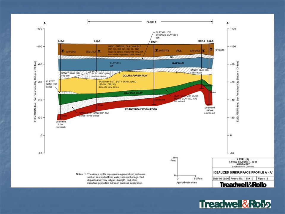
11
Typical Stratigraphic Layers
Fill Dune Sand Bay Mud Colma Formation Old Bay Clay Franciscan Complex Bedrock

13
Typical Stratigraphic Layers
Fill Heterogeneous soil consisting of: sands, clays, silts, gravels, construction debris Engineered fill or not? If not-engineered fill, can not be relied upon for foundation support

14
Typical Stratigraphic Layers
Dune Sand clean fine-grained sand, wind-blown deposit covers the majority of San Francisco Typically loose in upper 10’ Typically medium dense, 10’ to 30’ Typically dense below 30’

15
Typical Stratigraphic Layers
Bay Mud consists of clay and silt with occasional sand lenses and organic material relatively low strength material relatively compressible material If underlain by new fill, it could settle, causing downdrag on piles

16
Typical Stratigraphic Layers
Colma Formation consists predominantly of sands with occasional clay lenses typically contains between 0 to 20% silt/clay relatively strong material relatively incompressible material excellent foundation support

17
Typical Stratigraphic Layers
Old Bay Clay consists of stiff to hard overconsolidated clay may contain sand and gravel lenses relatively strong moderately compressible

18
Typical Stratigraphic Layers
Franciscan Complex bedrock deformed bedding planes and shear zones due to seismic activity highly variable hardness & strength moderately to highly weathered Relatively strong and incompressible excellent foundation support

19
Geology and Seismicity
Regional Geology Seismicity & Faulting distance to faults Geologic Hazards ground shaking liquefaction lateral spreading landsliding tsunami

20
Discussion, Conclusions & Recommendations
discuss issues, alternatives, implications conclude foundations type and settlement, shoring, soil improvement Recommendations provide recommendations regarding the geotechnical aspects of the project

21
Settlement Consolidation Liquefaction Seismic Densification
A slow process of squeezing water out in soft clay, resulting in denser packing of soil particles, when overlain by new fill Liquefaction Temporary loss of shear strength in loose sand due to a rise in excess pore water pressure generated by strong seismic shaking Seismic Densification Densification of loose sand above the water table due to ground shaking Foundation Settlement

22
Groundwater Depth groundwater encountered Likely fluctuations Design

23
Ground Improvement Stone columns Compaction grouting Chemical grouting
Jet grouting Dynamic compaction

24
Foundations The most appropriate foundation type depends on:
Subsurface conditions Building type and size loading conditions basement levels Site constraints noise vibrations proximity to existing improvements proximity to bay, channel Economics

25
Shallow Foundations Footings isolated continuous grid (waffle) Mat
 Mat")
26
Shallow Foundations suitable where competent material is encountered at subgrade elevation can be used in fill where it is improved and building is small and light mat can be used to span localized areas of non-support mat can be used on softer soil in excavation where weight of structure is equal to or less than weight of soil removed

27
Deep Foundations Piers Piles

28
Piers Efficient – can use one large diameter pier in lieu of several piles Lengths can be adjusted in the field – reduce waste Derive capacity mainly from friction Use casing and/or drilling fluid if groundwater and/or loose soil is present

29
Driven Pile Concrete piles are economical in Bay Area
Use where soft soil or un-documented fill is present Can be used at sites with high groundwater table or thick Bay Mud Fabricated at yard (concrete) – good quality control Moderately high capacity
 – good quality control. Moderately high capacity.")
30
Retaining Walls Restrained vs. Unrestrained Walls
Design wall pressure is higher for restrained walls Drained vs. Undrained Walls undrained walls are designed to resist hydrostatic pressure Drainage drainage panels gravel drain weep holes/pipes Waterproofing where moisture transmission is unacceptable

31
Floor Slabs Slab-on-grade Structural slab supported on ground
less expensive will lose support and settle/crack if settlement occurs beneath slab Structural slab supported on foundations more expensive can span areas of non-support due to liquefaction and/or settlement

32
Floor Slabs Vapor Barrier
typically included beneath floor slabs above the water table consists of: 4” crushed rock 10+ mil visqueen 2” sand alternatives include Griffolyn T65-G easier to install takes less space more expensive perform moisture emission testing prior to placement of floor covering

33
Seismic Design Provide site class (A through F)
Provide spectral acceleration values for Maximum Considered Earthquake (MCE) and Design Earthquake (DE)
 and Design Earthquake (DE)")
34
Seismic Design Site Class A hard rock B rock
C very dense soil and soft rock D stiff soil profile E soft soil profile F liquefiable more than 10 feet of peat more than 25 feet of very high plasticity clays (PI>75) more than 120 feet of soft/medium stiff clay (Bay Mud)
 more than 120 feet of soft/medium stiff clay (Bay Mud)")
35
Excavation Allowable slopes Shoring Dewatering

36
Site Preparation & Earthwork
remove pavements, organics abandon utilities abandon/remove old foundations overexcavation Earthwork compaction requirements acceptable fill materials

37
Utilities Settlement hangers flexible connections sleeved connections

38
Pavements Flexible Rigid Pavers pedestrian vehicular

39
Site Drainage Keep water away from building
Collect all downspouts and surface water All water should be directed to storm drain

40
Additional Geotechnical Services
Review geotechnical aspects of plans and specifications Observation geotechnical aspects of construction confirm subsurface conditions are as expected contractor performs work in accordance with plans and specifications

41
Limitations Conclusions and recommendations are based on limited subsurface exploration We should provide observation services to check work is completed per plans, specs, and our recommendations

Similar presentations


 Session 11 Course: S0892 - Ground Improvement Method Year: 2010.>")


 Geotechnical Properties of Soil>")


