Download presentation
Presentation is loading. Please wait.

1
ENGINEERING MECHANICS (15BS105)
SESSION NO.9

2
Session Outcomes At the end of this session, Students will be able to
Understand the real time application of a truss structure. Analyze the internal forces in a stable truss. Solve relevant problems.

3
SESSION PLAN 05 25 15 20 Time in Minutes Topic
Blooms Taxonomy Level-1 Blooms Taxonomy Level-2 Blooms Taxonomy Level-3 05 Introduction: Recap of moment of a force about a point, line or axis. 25 Sub-topic-1 (Lecture) Introduction to Truss, applications, assumptions, types of truss (perfect, imperfect & redundant). Zero force members. Method to find out internal forces in the members of a stable truss. (Physical model, windows software, presentation & animation assisted). Solution of relevant text book problems by method of joints.(Problem set-4.3) 15 Participative session Quiz Sub-topic-2 (Lecture) 20 Assignment problems will be practiced by students manually & using windows software. Conclusion Session will be concluded by discussing types of trusses and methods to find out internal forces in the members of a stable truss. 95 Minutes Total Contact Session + 5 Minutes for Attendance and Transition activities = 100 minutes
 Introduction to Truss, applications, assumptions, types of truss (perfect, imperfect & redundant). Zero force members. Method to find out internal forces in the members of a stable truss. (Physical model, windows software, presentation & animation assisted). Solution of relevant text book problems by method of joints.(Problem set-4.3) 15. Participative session. Quiz. Sub-topic-2 (Lecture) 20. Assignment problems will be practiced by students manually & using windows software. Conclusion. Session will be concluded by discussing types of trusses and methods to find out internal forces in the members of a stable truss. 95 Minutes Total Contact Session + 5 Minutes for Attendance and Transition activities = 100 minutes.")
4
Examples

5
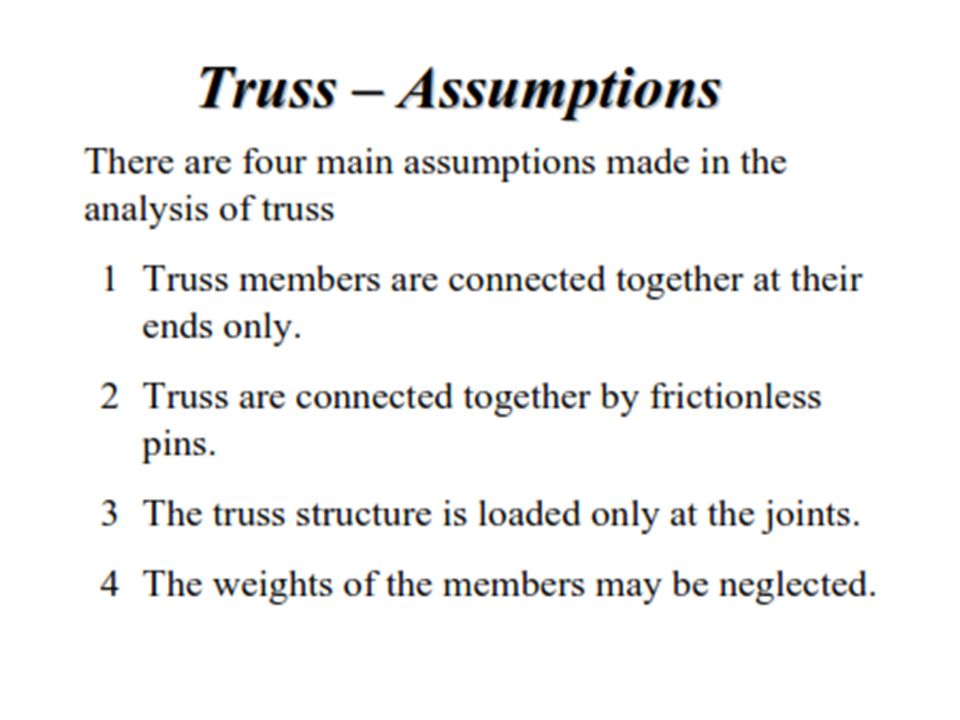
Introduction Three categories of engineering structures are: Frames: contain at least one multi-force member, i.e., member acted upon by 3 or more forces. Trusses: formed from two-force members, i.e., straight members with end point connections Machines: structures containing moving parts designed to transmit and modify forces.

6
Transmission of force through members of truss
ANIMATION

7
Definition of a Truss A truss is a fully constrained and stationary structure used for supporting loads. It has two force and straight members connected by joints at their ends. When forces tend to pull the member apart, it is in tension. When the forces tend to compress the member, it is in compression.

9
Types of trusses

10
MAXWELL'S TRUSS EQUATION: To distinguish between "statically determinate structure" and "statically indeterminate structure" Maxwell formulated an equation involving the number of linkages (m) and number of joints (j). The trusses which satisfies the equation, m = 2j - 3 are statically determinate structures and named as "Perfect Trusses". If m > 2j - 3, then the number of linkages are more than required, hence, called as "Redundant Trusses". Where as if m < 2j - 3 for any truss, then the number of linkages are less than that of a perfect truss. These kinds of trusses are called as "Deficient Trusses".

11
Simple Trusses A rigid truss will not collapse under the application of a load. A simple truss is constructed by successively adding two members and one connection to the basic triangular truss. In a simple truss, m = 2j- 3 where m is the total number of members and j is the number of joints.

12
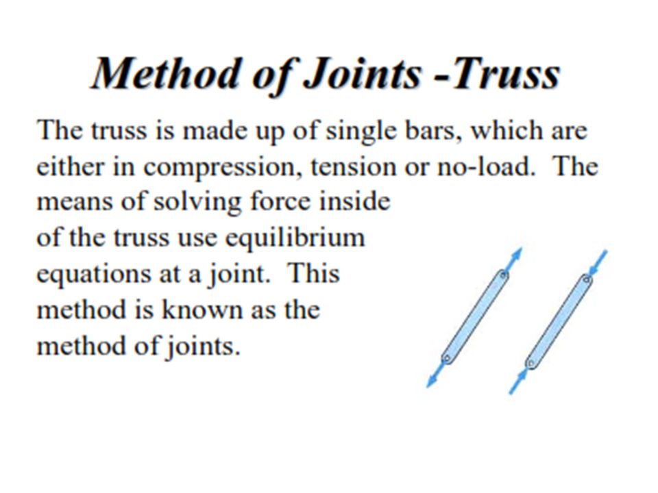
Analysis of trusses Method of Joints Method of Sections

15
Quiz What are different types of structures? Define truss?
Distinguish truss and frame? How do you form a simple truss? How do you check a truss is rigid? How do you analyse internal forces of members of a truss?

16
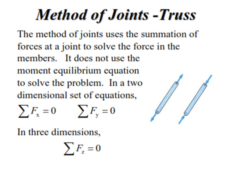
Analysis of Trusses by the Method of Joints
Dismember the truss and create a freebody diagram for each member and pin. The two forces exerted on each member are equal, have the same line of action, and opposite sense. Forces exerted by a member on the pins or joints at its ends are directed along the member and equal and opposite. Conditions of equilibrium on the pins provide 2n equations for 2n unknowns. For a simple truss, 2n = m May solve for m member forces and 3 reaction forces at the supports. Conditions for equilibrium for the entire truss provide 3 additional equations which are not independent of the pin equations.

17
Zero Force Members Truss analysis using the method of joints is greatly simplified if one is able to determine those members which support no loading (zero-force members) These zero-force members are used to increase stability of the truss during construction and to provide support if the applied loading is changed
 These zero-force members are used to increase stability of the truss during construction and to provide support if the applied loading is changed.")
18
If only two members form a truss joint and no external load or support reaction is applied to the joint, the members must be zero-force members. If three members form a truss for which two of the members are collinear, the third member is a zero-force member provided no external force or support reaction is applied.

19
Zero-force members Frequently the analysis can be simplified by identifying members that carry no load two typical cases are found When only two members form a non-collinear joint and there is no external force or reaction at that joint, then both members must be zero-force If either TCB or TCD ≠ 0, then C cannot be in equilibrium, since there is no restoring force towards the right. Hence both BC and CD are zero-load members here. P A B C D E

20
When three members form a truss joint for which two members are collinear and the third is at an angle to these, then this third member must be zero-force in the absence of an external force or reaction from a support Here, joint B has only one force in the vertical direction. Hence, this force must be zero or B would move (provided there are no external loads/reactions) Also TAB = TBC A B C D TBC TAB TBD B E
 Also TAB = TBC. A. B. C. D. TBC. TAB. TBD. B. E.")
21
While zero-force members can be removed in this configuration, care should be taken
any change in the loading can lead to the member carrying a load the stability of the truss can be degraded by removing the zero-force member P You may think that we can remove AD and BD to make a triangle … This satisfies the statics requirements However, this leaves a long CE member to carry a compressive load. This long member is highly susceptible to failure by buckling. A B C D E

22
Problem set-4.3 C 1 2 3 60° A B 4 D 5 P 1. Calculate the axial force in each bar of the simple truss supported and loaded as shown in the figure. The triangle ACB is isosceles with 30ᵒ angles at A and B and P = 5 kN.

23
Problem set-4.3 E C F A H B D G P 2. Prove that a tensile force equal to the applied load P is produced in the bar DE of the truss shown in the figure.

24
Problem set-4.3 500 N 500 N 0.6 m 0.6 m 4 1 3 5 2 0.9 m 6 4. Determine the axial force in each bar of the plane truss loaded as shown in the figure.

25
Problem set-4.3 3 m 3 m 6 1.5 m 1 5 3 1.5 m 2 4 P 7. Determine the axial force in each bar of the plane truss loaded as shown in the figure.

26
Problem set-4.3 3 m 3 m 6 1.5 m 1 5 3 1.5 m 2 4 P 7. Determine the axial force in each bar of the plane truss loaded as shown in the figure.

27
Problem set-4.3

28
Problem set-4.3 8 45° 6 9 7 5 2 4 3 1 45° 5 kN 5 kN 9. Determine the axial force Si in each bar of the plane truss supported and loaded as shown in the figure.

Similar presentations


 Structural Analysis>")


