Download presentation
Presentation is loading. Please wait.

2
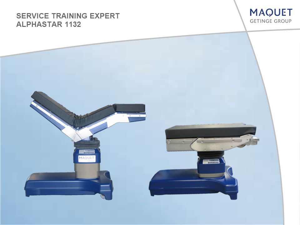
SERVICE TRAINING EXPERT ALPHASTAR 1132

3
© MAO-SE-TC 1132_SE_EX_Handout_EN_12_2012 3 Collision protection switch Collision protection switch retrofit Remote control with back lit Adjustment of the IR code on an IR transmitter with back lit New potentiometer for the leg and the back plate Change of the hydraulic pressure Modification of the Hydraulic pump 1132.2XXX ALPHASTAR PRO Production stop for 1132.11XX and 1132.12XX 1. Modifications : TOPICS

4
© MAO-SE-TC 1132_SE_EX_Handout_EN_12_2012 4 Since May 2007 the OR tables are equipped with a so-called collision protection switch. The collision protection switch is activated if for example the leg plates are moved downward by -90° and the height function is also moved down. Only the “height up“ and the back rest plate functions can be moved while the collision protection switch is activated. A “beep“ signal is generated when other functions are actuated by means of the remote control. Collision protection switch (Since May 2007) COLLISION PROTECTION SWITCH
 COLLISION PROTECTION SWITCH.")
5
© MAO-SE-TC 1132_SE_EX_Handout_EN_12_2012 5 The collision protection switch can be installed later for older O.R. tables. There are 2 retrofit sets for the different Alphastar models (1132.0XXX und 1132.1XXX). They consist of a control PCB, the corresponding micro controllers, the micro switches, supports, wires, the instructions and 2 cover caps. The 2 cover caps are used to cover visible damages at the corners of the large part of the OR table base. The cover caps can also be ordered separately. COLLISION PROTECTION SWITCH RETROFIT
. They consist of a control PCB, the corresponding micro controllers, the micro switches, supports, wires, the instructions and 2 cover caps. The 2 cover caps are used to cover visible damages at the corners of the large part of the OR table base. The cover caps can also be ordered separately. COLLISION PROTECTION SWITCH RETROFIT.")
6
© MAO-SE-TC 1132_SE_EX_Handout_EN_12_2012 6 The difference between the 2 retrofit sets is that different micro controllers are used (1132.0XX has 4 potentiometers,1132.1XX has 5 potentiometers). The retrofit kit for 1132.0XXX includes a new spiral cable in addition. The spiral cable of the 1132.0XXX has only 11 wires. A 12th wire (red/blue wire) is necessary to send the signal from the collision protection switch to the control PCB. This wire is already included in the spiral cable of the 1132.1XXX. For more information see the retrofit instructions. The control PCB and the micro controller must be replaced. A jumper (J1) must be removed to enable the controller unit to evaluate the status of the collision protection switch. If the control PCB has to be replaced in an O.R. table with no collision protection switch jumper J1 must be left plugged in. COLLISION PROTECTION SWITCH RETROFIT
 is necessary to send the signal from the collision protection switch to the control PCB. This wire is already included in the spiral cable of the XXX. For more information see the retrofit instructions. The control PCB and the micro controller must be replaced. A jumper (J1) must be removed to enable the controller unit to evaluate the status of the collision protection switch. If the control PCB has to be replaced in an O.R. table with no collision protection switch jumper J1 must be left plugged in. COLLISION PROTECTION SWITCH RETROFIT.")
7
© MAO-SE-TC 1132_SE_EX_Handout_EN_12_2012 7 ┴ Circuit ground X5 X6 X7 Tilting X8 Trendelenburg X9 Back plate X10 Leg plate X11 Height X3 -1:WH 0V. -2:GN 24V. permanent -3:BN 24V. valves -4:YE Signal Pump on -5:GY Mains on -6:PK Data -7:BK V. Lock -8:RD V. Unlock -9:BK S. Lock -10:VT S. Unlock -11:GY/PK 24V. -12:RD/BU S. Collision * X1 Jumper J1 CONTROL PCB

8
© MAO-SE-TC 1132_SE_EX_Handout_EN_12_2012 8 The 2 wires of the collision protection switch have to be connected to the socket X2 on the charger board in parallel to the 2 wires of the spiral cable. One wire on pin 1 (White wire: Circuit ground). The second wire on pin 12 (Red/ blue wire: Signal from the collision protection switch). The charger board was modified at the beginning of the year 2007. A further socket (X7) was added to enable connection of the 2 wires to separate terminals X2 Connection to the controller A1 X7 S. collision (Since the beginning of 2007) Pin 1: White Circuit ground Pin 12: red/blue Signal from the collision protection switch COLLISION PROTECTION SWITCH RETROFIT
. The second wire on pin 12 (Red/ blue wire: Signal from the collision protection switch). The charger board was modified at the beginning of the year A further socket (X7) was added to enable connection of the 2 wires to separate terminals X2 Connection to the controller A1 X7 S. collision (Since the beginning of 2007) Pin 1: White Circuit ground Pin 12: red/blue Signal from the collision protection switch COLLISION PROTECTION SWITCH RETROFIT.")
9
© MAO-SE-TC 1132_SE_EX_Handout_EN_12_2012 9 Corded hand control with Back lit 1132.90J0 OR tables delivered before September 2008 can be controlled without any modification Effective by 01.09.2008 the IR transmitter and corded hand controls were replaced by new versions with backlit key pads: To charge the batteries of an IR transmitter with Back lit a new charger is necessary: 1009.70A0 IR hand control with Back lit 1132.91J0 1132.11/12/13XX delivered before September 2008 have to be retrofitted to be controlled by means of the IR transmitter (Micro controller and control PCB) 1132.01/02/03XX can not be controlled by means of the IR transmitter. For more information see retrofit instructions REMOTE CONTROL WITH BACK LIT

10
© MAO-SE-TC 1132_SE_EX_Handout_EN_12_2012 10 If no action is done for 30 seconds the IR transmitter will return to the normal status Activating the Adjustment mode : Press the pairs of keys simultaneously for 2 sec. In the following order : Trend and Rev Tilt L. and Tilt R. Up and Down (A short acoustic signal confirms the different steps) The setting of the IR code on a IR transmitter with Back lit is different compared to the older IR transmitter. The LEDs will blink as a confirmation. SETTING OF THE IR SYSTEM CODE AT THE IR TRANSMITTER REMOTE CONTROL WITH BACK LIT
 The setting of the IR code on a IR transmitter with Back lit is different compared to the older IR transmitter. The LEDs will blink as a confirmation. SETTING OF THE IR SYSTEM CODE AT THE IR TRANSMITTER REMOTE CONTROL WITH BACK LIT.")
11
© MAO-SE-TC 1132_SE_EX_Handout_EN_12_2012 11 Adjustment : Press the Tilt L. key: The LED´s indicate the adjusted IR Code (HB) Change of the IR Code is acknowledged by actuation of the Level button for about 3 seconds Mark the IR transmitter with the new IR code by means of the included letters and numbers stickers SETTING OF THE IR SYSTEM CODE AT THE IR TRANSMITTER REMOTE CONTROL WITH BACK LIT IR digit 0 IR digit 1 IR digit 2 IR digit 3 IR digit 4 IR digit 5 IR digit 6 IR digit 7 IR digit 8 IR digit 9 IR digit A IR digit B IR digit C IR digit D IR digit E IR digit F IR Code table Press the Tilt R. key: The LED´s indicate the adjusted IR Code (LB) Press and hold down Tilt L. followed by Up or Down to change the IR The LED´s indicate the adjusted IR Code (HB). Same procedure with Tilt R. for the IR Code (LB)
 Change of the IR Code is acknowledged by actuation of the Level button for about 3 seconds Mark the IR transmitter with the new IR code by means of the included letters and numbers stickers SETTING OF THE IR SYSTEM CODE AT THE IR TRANSMITTER REMOTE CONTROL WITH BACK LIT IR digit 0 IR digit 1 IR digit 2 IR digit 3 IR digit 4 IR digit 5 IR digit 6 IR digit 7 IR digit 8 IR digit 9 IR digit A IR digit B IR digit C IR digit D IR digit E IR digit F IR Code table Press the Tilt R. key: The LED´s indicate the adjusted IR Code (LB) Press and hold down Tilt L. followed by Up or Down to change the IR The LED´s indicate the adjusted IR Code (HB). Same procedure with Tilt R. for the IR Code (LB).")
12
© MAO-SE-TC 1132_SE_EX_Handout_EN_12_2012 12 The leg and back plate potentiometer were replaced by a new model since the middle of the year 2008. The old potentiometers are no more available. The retrofit set includes 2 new potentiometers, plugs and sockets, instructions, and replacement cover plates for the potentiometers. Potentiometer for the leg plates and the backrest The cover plates must be replaced with the potentiometers. A plastic screw fixed in the cover plate is used to guide the potentiometers. The fork on the potentiometer fixation is secured against by means of the plastic screw in the cover plate to prevent it from rotating. Cover plate for the leg plate potentiometer: 2 version depending on the OR table model Cover plate for the back plate potentiometer REPLACEMENT OF A POTENTIOMETER

13
© MAO-SE-TC 1132_SE_EX_Handout_EN_12_2012 13 Since the beginning of the year 2009 the over pressure valve is adjusted to 115 +5 bar. Re-adjustment of the hydraulic pressure on older OR tables is not intended to be done by the service. Current consumption of the hydraulic unit is normally between 6 and 7,5 Amp. at the max. pressure. If the current is higher than 9 Amp. the hydraulic unit must be replaced. CHANGE OF THE HYDRAULIC PRESSURE

14
© MAO-SE-TC 1132_SE_EX_Handout_EN_12_2012 14 At the beginning of the year of 2009 the hydraulic pump was replaced by a new model. The motor can not be separated from the pump. The hydraulic unit must be replaced as a complete spare part. For older OR tables the motor can be separated from the pump as long as spare parts are available. Afterwards the hydraulic pump must be replaced by a modification set that consists of the new hydraulic pump and the fixation. The hydraulic pump (without the fixation) can also be ordered for OR tables which are already equipped with the new hydraulic pump. MODIFICATION OF THE HYDRAULIC PUMP
 can also be ordered for OR tables which are already equipped with the new hydraulic pump. MODIFICATION OF THE HYDRAULIC PUMP.")
15
© MAO-SE-TC 1132_SE_EX_Handout_EN_12_2012 15 Europa USA ALPHASTAR PRO ALPHASTAR PRO (low) 1132.21B0 1132.21B2 1132.22B0 1132.22B2 1132.21F0 1132.21F2 1132.22F0 1132.22F2 x x The 1132.21XX and the 1132.22XX are a combination of the base and the column of the 1132.1XXX and the table top of the 1131.12XX IR transmitter and corded hand control are optional. Only the remote controls with back lit are compatible with 1132.2X. 1132.2XXX ALPHASTAR PRO New versions of the ALPHASTAR, 1132.2XXX so-called ALPHASTAR PRO, have been produced along with the existing versions since 07/2010.

16
© MAO-SE-TC 1132_SE_EX_Handout_EN_12_2012 16 RANGE OF ADJUSTMENT 1132.2XXX Trendelenburg: +30°/ -30° Tilting: +18°/ -18° Backrest: +70°/ -40° Leg plates: +80°/ -90° Capacity for patient loads (Patient and accesories): up to 454 kg Weight of the O.R. table itself: approx. 300 kg Height: for 1132.21: 685 -1125 mm for 1132.22: 598 - 950 mm

17
© MAO-SE-TC 1132_SE_EX_Handout_EN_12_2012 17 RANGE OF ADJUSTMENT 1132.2XXX Flex Position Normal: trendelenburg : +20° backrest : -20° Flex Position Reverse: trendelenburg : -30° leg plate : -30° Reflex Position Normal: trendelenburg : -30° backrest : +40° Reflex Position Reverse: trendelenburg : +30° leg plate : +40°

18
© MAO-SE-TC 1132_SE_EX_Handout_EN_12_2012 18 ACOUSTIC SIGNALS 1132.2XXX Level position reached (except leg plates) Level position reached (including leg plates) Neurolock is active Adjustment mode is active Potentiometer at level position (2,5V.+/-0,2V.) The acoustic signals are the same as for the BETASTAR.
 Level position reached (including leg plates) Neurolock is active Adjustment mode is active Potentiometer at level position (2,5V.+/-0,2V.) The acoustic signals are the same as for the BETASTAR.")
19
© MAO-SE-TC 1132_SE_EX_Handout_EN_12_2012 19 Leg plate potentiometer Backrest potentiometer Backrest cylinders Leg plate cylinders Trendelenburg potentiometer Tilting potentiometer TABLE TOP 1132.2XXX

20
© MAO-SE-TC 1132_SE_EX_Handout_EN_12_2012 20 For more information on repair work and adjustment see the repair manual REPAIRS AND AJUSTMENT OF THE 1132.2X TABLE TOP Repair work and adjustment procedures for the table top of an ALPHASTAR PRO 1132.2XX are the same as for the BETASTAR 1131.12XX table top.

21
© MAO-SE-TC 1132_SE_EX_Handout_EN_12_2012 21 PRODUCTION STOP FOR 1132.11XX AND 1132.12XX From January 2013 the O.R. tables 1132.11XX and 1132.12XX will be no longer in production. Except the models 1132.21XX and 1132.22XX Alphastar PRO.

22
THANK YOU FOR YOUR ATTENTION

Similar presentations


 2.Wired barcode scanner holder (optional) 3.Mouse holder and tray 4. Removable rear technology panel 5. Power cord.>")


