Download presentation
Presentation is loading. Please wait.

1
Supparerk Prichayudh M.D
Pacemaker Supparerk Prichayudh M.D

3
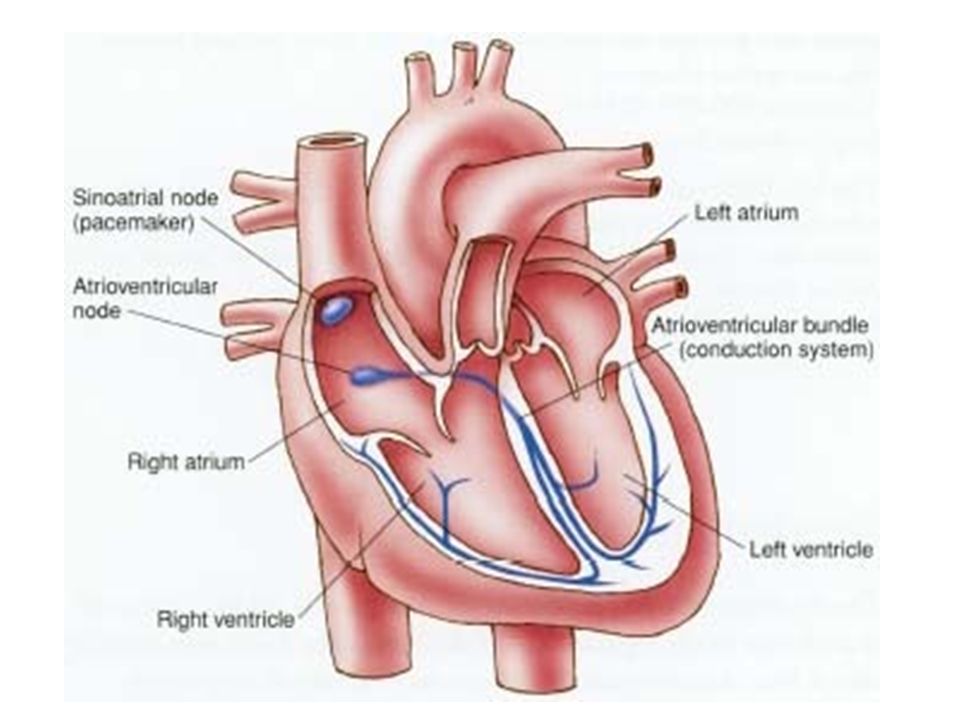
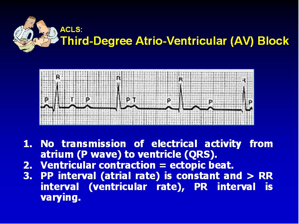
Normal EKG P wave = atrial depolarization
QRS wave = ventricular depolarization T wave = ventricular repolarization

4
Outline Indications Types Modes of pacemaker Temporary pacemaker
Problems with pacemakers Surgical diathermy and pacemakers

5
Indications

6
Indication: Symptomatic bradycardia
Sinus node dysfunction 3° and advanced 2° AV block Bradycardia associated with AMI

7
Prophylactic Implant Patients with LBBB requiring Swan-Ganz catheter placement Cardioversion in the setting of SSS New BBB in the setting of acute endocarditis Peri-operatively

8
Sick Sinus Syndrome

13
Types Temporary Permanent

14
Permanent pacemaker Box = pulse generator

15
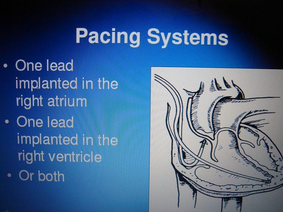
Pacemaker Leads Pacemaker leads are the conduits from the generator to the myocardium. Most leads are implanted transvenously.

16
Wiring systems Unipolar Bipolar One electrode on the heart (-)
Signals return through body fluid and tissue to the pacemaker (+) Bipolar Two electrodes on the heart (- & +) Signals return to the ring electrode (+) above the lead (-) tip
 Bipolar. Two electrodes on the heart (- & +) Signals return to the ring electrode (+) above the lead (-) tip.")
17
UNIPOLAR AND BIPOLAR PACING

19
Modes of pacemaker

20
NASPE-BPEG Generic Five-Position Code
Position I II III IV V Parameter measured Chamber(s) paced Chamber(s) sensed Response to sensing Rate modulation Anti-tachyarrhythmia function Possible values O = None A = Atrium I = Inhibited R = Rate modulation on P = Pace V = Ventricle T = Triggered S = Shock D = Dual (A + V) D = Dual (I + T) D = Dual NASPE, North American Society of Pacing and Electrophysiology; BPEG, British Pacing and Electrophysiology Group
 paced. Chamber(s) sensed. Response to sensing. Rate modulation. Anti-tachyarrhythmia function. Possible values. O = None. A = Atrium. I = Inhibited. R = Rate modulation on. P = Pace. V = Ventricle. T = Triggered. S = Shock. D = Dual (A + V) D = Dual (I + T) D = Dual. NASPE, North American Society of Pacing and Electrophysiology; BPEG, British Pacing and Electrophysiology Group.")
21
First letter: Chamber Paced
V- Ventricle A- Atrium D- Dual (A & V) O- None
 O- None.")
22
Second letter: Chamber Sensed
V- Ventricle A- Atrium D- Dual (A & V) O- None
 O- None.")
23
Third letter: Sensed Response
T- Triggers Pacing I- Inhibits Pacing (demand) D- Dual (synchronous) O- None (asynchronous)
 D- Dual (synchronous) O- None (asynchronous)")
24
Chamber Paced Atrial pacing Ventricular pacing
Intact AV conduction system required Ventricular pacing Loss of atrial kick Atrial/Ventricular pacing Natural pacing Atrial-ventricular synchrony

25
Commonly used modes AAI - atrial demand pacing
VVI - ventricular demand pacing DDD – Dual chamber pacemaker AOO - atrial asynchronous pacing VOO - ventricular asynchronous pacing

26
ventricular asynchronous pacing VOO
Indications Temporary mode some-times used during surgery to prevent interference from electrocautery

27
ventricular demand pacing VVI
Indications The combination of AV block and chronic atrial arrhythmias (particularly atrial fibrillation).
.")
28
atrial demand pacing AAI
Indications Sick sinus syndrome in the absence of AV node disease or atrial fibrillation.

29
atrial synchronous ventricular inhibited pacemaker VDD
Indications AV block with intact sinus node function (particularly useful in congenital AV block).
.")
30
Dual chamber pacemaker DDD
Indications 1. The combination of AV block and SSS. 2. Patients with LV dysfunction and LV hypertrophy who need coordination of atrial and ventricular contractions to maintain adequate CO.

31
Temporary pacemaker

32
Types Transvenous- pacing wire via central line to RV under X ray, usually bipolar i.e., with 2 electrodes at the end of wire Transthoracic (epicardial lead) post op pacer wires. Transcutaneous one electrode over cardiac apex, other over right scapula or clavicle. Transesophageal
 post op pacer wires. Transcutaneous one electrode over cardiac apex, other over right scapula or clavicle. Transesophageal.")
33
Transcutaneous pacemaker
Posterior Lt side of the spine, behind the scapula, directly behind the anterior electrode. Avoid placement over bone. Anterior Upper = below nipple, center =V2, V3 position, Female= under the breast, above diaphragm. Output Increase gradually until captures, then increase 10% more. Require sedation and analgesia.

34
Transvenous pacemaker

40
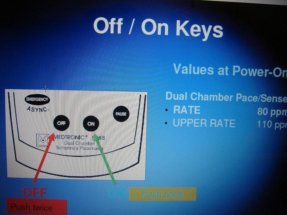
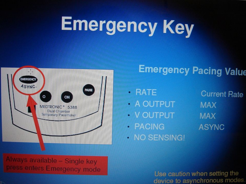
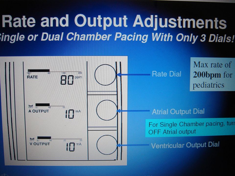
Medtronic 5388 Dual Chamber

44
Setting Atrial and ventricular output (lowest possible)
Milliamperes (mA) Typical atrial mA 5 Typical ventricular mA 8-10 Atrial/ventricular rate Set at physiologic rate for individual patient Post open heart sugery 90/min AV Interval, upper rate, & PVARP automatically adjust with set rate changes Atrial and ventricular sensitivity Millivolts (mV) Typical atrial: 0.4 mV Typical ventricular: 2.0mV
 Typical atrial mA 5. Typical ventricular mA Atrial/ventricular rate. Set at physiologic rate for individual patient. Post open heart sugery 90/min. AV Interval, upper rate, & PVARP automatically adjust with set rate changes. Atrial and ventricular sensitivity. Millivolts (mV) Typical atrial: 0.4 mV. Typical ventricular: 2.0mV.")
45
Setting (cont.) AV Interval Milliseconds (msec) Upper rate
Time from atrial sense/pace to ventricular pace Synonymous with “PR” interval Upper rate Automatically adjusts to 30 bpm higher than set rate Prevents pacemaker mediated tachycardia from unusually high atrial rates Wenckebach-type rhythm results when atrial rates are sensed faster than the set rate Refractory period PVARP: Post Ventricular Atrial Refractory Period Time after ventricular sensing/pacing when atrial events are ignored

48
Normal Pacing Atrial Pacing Atrial pacing spikes followed by P waves

49
Normal Pacing Ventricular pacing
Ventricular pacing spikes followed by wide, bizarre QRS complexes

50
Normal Pacing A-V Pacing
Atrial & Ventricular pacing spikes followed by atrial & ventricular complexes

51
Normal Pacing DDD mode of pacing Ventricle paced at atrial rate

52
Assessing Underlying Rhythm

53
Problems with pacemakers

54
Problems with pacemakers
Failure to pace Failure to capture Failure to sense (overpacing) Wenkebach Pacemaker syndrome
 Wenkebach. Pacemaker syndrome.")
55
1. Failure to Pace Causes: Oversensing Battery failure
Braunwald's Heart Disease: A Textbook of Cardiovascular Medicine, 7th ed., 2005. Causes: Oversensing Battery failure Internal insulation failure Conductor coil fracture

56
Problems with Pacemakers Failure to Pace
Braunwald's Heart Disease: A Textbook of Cardiovascular Medicine, 7th ed., 2005. Causes: Crosstalk (V oversensing when A paced)
")
57
Oversensing Pacing does not occur when intrinsic rhythm is inadequate

58
Oversensing Causes Danger - heart block, asystole
Pacemaker inhibited due to sensing of “P” waves & “QRS” complexes that do not exist Pacemaker too sensitive Possible wire fracture, loose contact Pacemaker failure Danger - heart block, asystole

59
Oversensing Solution View rhythm in different leads Change electrodes
Check connections Decrease pacemaker sensitivity (↑mV) Change cables, battery, pacemaker Reverse polarity Check electrolytes Unipolar pacing with subcutaneous “ground wire”
 Change cables, battery, pacemaker. Reverse polarity. Check electrolytes. Unipolar pacing with subcutaneous ground wire")
60
Reversing polarity Changing polarity Requires bipolar wiring system
Reverses current flow Switch wires at pacing wire/bridging cable interface

61
2. Failure to Capture Atrial non-capture
Atrial pacing spikes are not followed by P waves

62
Failure to Capture Ventricular non-capture
Ventricular pacing spikes are not followed by QRS complexes

63
Failure to Capture Causes Danger - poor cardiac output
Insufficient energy delivered by pacer Low pacemaker battery Dislodged, loose, fibrotic, or fractured electrode Electrolyte abnormalities Acidosis Hypoxemia Hypokalemia Danger - poor cardiac output

64
Failure to Capture Solutions View rhythm in different leads
Change electrodes Check connections Increase pacer output (↑mA) Change battery, cables, pacer Reverse polarity
 Change battery, cables, pacer. Reverse polarity.")
65
3. Failure to Sense (overpacing)
Atrial undersensing Atrial pacing spikes occur regardless of P waves Pacemaker is not “seeing” intrinsic activity

66
Failure to Sense Ventricular undersensing
Ventricular pacing spikes occur regardless of QRS complexes Pacemaker is not “seeing” intrinsic activity

67
Competition Pacemaker & patient’s intrinsic rate are similar
Unrelated pacer spikes to P wave, QRS complex Fusion beats

68
Failure to Sense Causes
Pacemaker not sensitive enough to patient’s intrinsic electrical activity (mV) Insufficient myocardial voltage Dislodged, loose, fibrotic, or fractured electrode Electrolyte abnormalities Low battery Malfunction of pacemaker or bridging cable
 Insufficient myocardial voltage. Dislodged, loose, fibrotic, or fractured electrode. Electrolyte abnormalities. Low battery. Malfunction of pacemaker or bridging cable.")
69
Failure to Sense Danger – potential (low) for paced ventricular beat to land on T wave (R on T) VF!!
 for paced ventricular beat to land on T wave (R on T) VF!!")
70
Failure to Sense Solution View rhythm in different leads
Change electrodes Check connections Increase pacemaker’s sensitivity (↓mV) Change cables, battery, pacemaker Reverse polarity Check electrolytes Unipolar pacing with subcutaneous “ground wire”
 Change cables, battery, pacemaker. Reverse polarity. Check electrolytes. Unipolar pacing with subcutaneous ground wire")
71
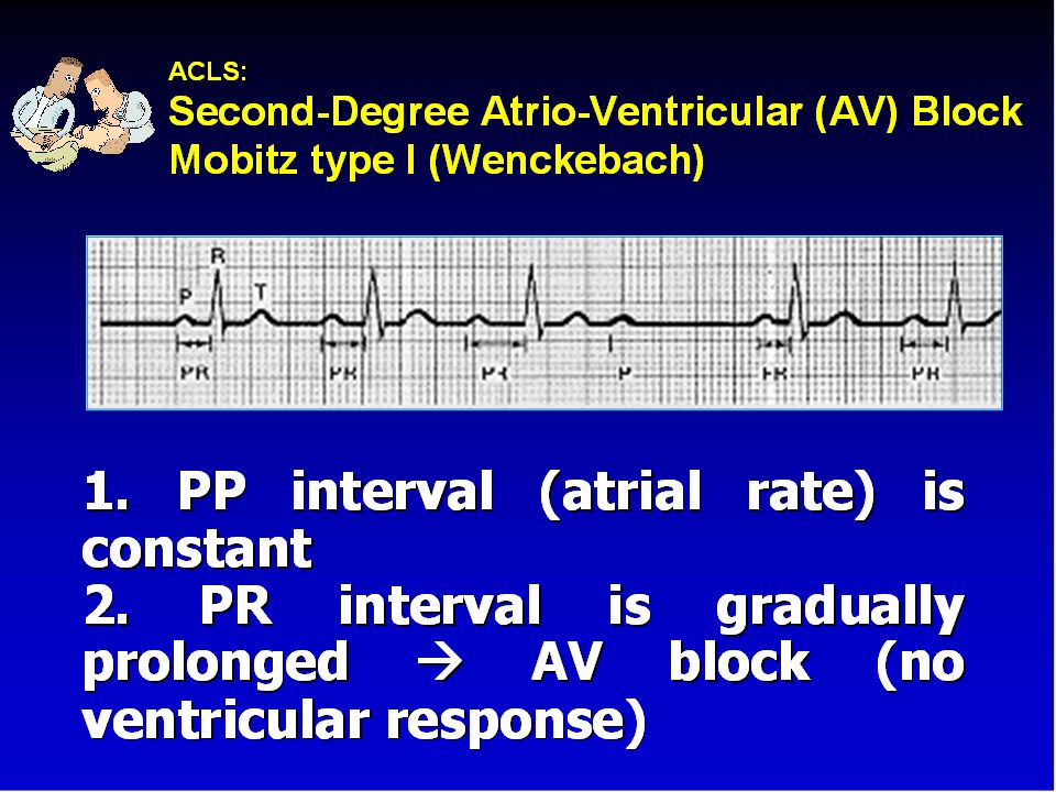
4. Wenckebach Assessment Appears similar to 2nd degree heart block
Occurs with intrinsic tachycardia

72
Wenckebach Causes DDD mode safety feature
Prevents rapid ventricular pacing impulse in response to rapid atrial rate Sinus tachycardia Atrial fibrillation, flutter Prevents pacer-mediated tachycardia Upper rate limit may be inappropriate

73
Wenckebach Solution Treat cause of tachycardia
Fever: Cooling Atrial tachycardia: Anti-arrhythmic Pain: Analgesic Hypovolemia: Fluid bolus Adjust pacemaker upper rate limit as appropriate

74
5. Pacemaker syndrome Ventricular pacing sacrifice the atrial contribution to ventricular output Loss of AV synchrony Atrium contracts against closed TV,MV ↓ CO, ↑ JVD Retrograde ventriculoatrial (VA) conduction inverted P, ↑ PR, AV dissociation Absence of rate response to physiologic need 14-57% in VVI Patients with intact VA conduction are at greater risk
 conduction inverted P, ↑ PR, AV dissociation. Absence of rate response to physiologic need % in VVI. Patients with intact VA conduction are at greater risk.")
75
Rx VVI Add A-lead, ↓ Rate
Other interrogation and reprogramming to fix loss of AV synchrony

76
Surgical diathermy and pacemakers

77
Ventricular fibrillation – most common if pacemaker unit is older type
Inhibition of demand function- sensing may be triggered, with resultant chamber inhibition or arrhythmias induced Unpredictable setting of programmable types Asystole Unit failure

78
Recommendations Place indifferent electrode on same side as operation & as far from pacemaker unit as possible Limit use of diathermy Use lowest current setting possible Use bipolar diathermy Careful monitoring of pulse, pulse oximetry & arterial pressure Transcutaneous pacing should be available Isoprenaline should be available Interrogation before Sx Magnet Reset PM to asynchronous Inactivate defribillation feature in AICD

79
Post operative care Full telemetric check
Reprogramming back to original setting

80
THANK YOU

Similar presentations


 Position I IIIII Category Chamber(s) Chamber(s) Response to paced sensed sensing.>")


