Download presentation
Presentation is loading. Please wait.

1
Grounding & Shielding Ved Prakash Sandlas Director General
Amity Institute of Space Science & Technology, Noida Principal Adviser, Cogent EMR Solutions Ltd, New Delhi ( ) Distinguished Scientist and Chief Controller R & D, DRDO ( ) Director, Defence Electronics Applications Lab (DEAL), Dehradun ( ) Group Director, Electronics, VSSC, Thiruvanathapuram ( ) Project/Mission Director, SLV-3, ISRO ( ) AISST, Noida, Feb 8, 2010
 Distinguished Scientist and Chief Controller R & D, DRDO ( ) Director, Defence Electronics Applications Lab (DEAL), Dehradun ( ) Group Director, Electronics, VSSC, Thiruvanathapuram ( ) Project/Mission Director, SLV-3, ISRO ( ) AISST, Noida, Feb 8,")
2
REASONS FOR GROUNDING Lightning Protection to Buildings, Structures and Equipment Shock and Safety hazard control in Equipment, Laboratories, Hospitals and Homes Faraday Shielding of Cables Common Ground Reference for Measurements Common Mode EMI Filters Electrostatic Hazard Control Ground (Return) Line, Signal Return and Power Return Analog Ground, Digital Ground and Power Ground
 Line, Signal Return and Power Return. Analog Ground, Digital Ground and Power Ground.")
3
TRANSMISSION SYSTEM USING GROUND AS CURRENT RETURN PATH
TRANSMISSION LINE LOAD CURRENT GROUND RODS SOURCE LOAD RETURN CURRENT GROUND (EARTH) TRANSMISSION SYSTEM USING GROUND AS CURRENT RETURN PATH
 TRANSMISSION SYSTEM USING GROUND AS CURRENT RETURN PATH.")
4
SINGLE POINT OR STAR GROUNDING
1 2 3 SYSTEM GROUND 4 5 6 EARTH GROUND

5
MULTI POINT GROUNDING 1 2 3 GROUNDING BRAID CONDUCTING GROUND PLANE
GROUNDING LUGS TO EARTH GROUND

6
HYBRID GROUNDING RS RL VS C LOW FREQUENCY------------SINGLE POINT
SOURCE CHASSIS LOAD CHASSIS COAXIAL CABLE RS OUTER BRAID GROUNDED RL VS C LOW FREQUENCY GROUND HIGH FREQUENCY GROUND HYBRID GROUNDING LOW FREQUENCY SINGLE POINT HIGH FREQUENCY MULTI POINT

7
SAFETY GROUND AND EMI ISOLATION
POWER DISTRIBUTION PANEL COMPUTER (CPU) PERIPHERAL EARTH WIRE SAFETY GROUND AND EMI ISOLATION
 PERIPHERAL. EARTH WIRE. SAFETY GROUND AND EMI ISOLATION.")
8
_ _ CASSIS RETURN _ GROUND (EARTH) RETURN
+ POWER SUPPLY LOAD _ COMMON (FLOATING) RETURN + POWER SUPPLY LOAD _ CASSIS RETURN + POWER SUPPLY LOAD _ GROUND (EARTH) RETURN
 RETURN. + POWER SUPPLY. LOAD. _. CASSIS RETURN. + POWER SUPPLY. LOAD. _. GROUND (EARTH) RETURN.")
9
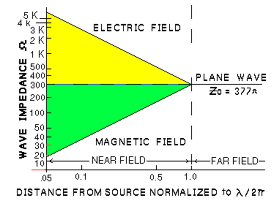
SHIELDING MECHANISM FOR PLANE WAVE
Incident Wave EY HZ EY EY HZ HZ EY EY HZ HZ Attenuated Wave Barrier of Finite Thickness SHIELDING MECHANISM FOR PLANE WAVE

10
Absorption Loss, A = 3.34 t √fGµ dB
Where, t = Shield thickness in mils f = Frequency in MHz G = Conductivity relative to Copper (Copper = 1, Aluminum = 0.61, Brass = 0.26, Iron = 0.17, Stainless Steel = 0.02) µ = Permeability relative to Vacuum (Copper = 1, Aluminum = 1, Brass = 1, Stainless Steel = 1 Iron = 1000, Mu Metal = 80,000, Perm Alloy = 80,000) 1 mil of Copper at 1 GHz shall give over 100 dB absorption loss 1/8 inch (~ 0.3 cm) Iron sheet at 50 Hz gives 50 dB absorption loss
 µ = Permeability relative to Vacuum. (Copper = 1, Aluminum = 1, Brass = 1, Stainless Steel = 1. Iron = 1000, Mu Metal = 80,000, Perm Alloy = 80,000) 1 mil of Copper at 1 GHz shall give over 100 dB absorption loss. 1/8 inch (~ 0.3 cm) Iron sheet at 50 Hz gives 50 dB absorption loss.")
11
Shielding Absorption Loss
dB 300 100 30 10 3 1 IRON 1/8 inch 1/8 inch 10 mils 10 mils 1 mil 1 mil COPPER k 10k 100k 1M 10M 100M 1G Frequency Hz

13
For Plane Wave, Reflection Loss:
R = log dB Reflection loss for plane wave at low frequencies is the major shielding mechanism Also, high G and low µ is more effective (low surface impedance compared to 377 ohms) Also, at high frequencies, the skin depth decreases or surface resistivity increases (surface impedance increases), reducing reflection loss At VHF and UHF, absorption loss is more important G µf
 Also, at high frequencies, the skin depth decreases or surface resistivity increases (surface impedance increases), reducing reflection loss. At VHF and UHF, absorption loss is more important. G. µf.")
14
Reflection Loss for Plane Wave
dB 250 200 150 100 50 COPPER IRON k 10k 100k 1M 10M 100M 1G Frequency Hz

15
For high impedance wave in near field (Electric Field)
R = log dB Where, r = Distance from source to barrier in inches (<< / 2) F = Frequency in Hz For low impedance wave in near field (Magnetic Field) R = 20 log √µ / FG r √FG / µ dB An interesting condition is achieved for magnetic field reflection loss for iron with 1 inch separation, where it approaches 0 dB at 30 kHz indicating matching of wave impedance and surface impedance G F3µr2 0.462 r
 F = Frequency in Hz. For low impedance wave in near field (Magnetic Field) R = 20 log √µ / FG r √FG / µ dB. An interesting condition is achieved for magnetic field reflection loss for iron with 1 inch separation, where it approaches 0 dB at 30 kHz indicating matching of wave impedance and surface impedance. G. F3µr r.")
16
Reflection Loss for Electric Fields
dB 250 200 150 100 50 COPPER r = 30m 1m 1inch 30m 1m r = 1 inch Plane Wave IRON k 10k 100k 1M 10M 100M 1G Frequency Hz

17
Reflection Loss for Magnetic Fields
dB 125 100 75 50 25 Plane Wave COPPER 30m 1m r = 1 inch r = 30m 1m 1inch IRON k 10k 100k 1M 10M 100M 1G Frequency Hz

18
ELECTRIC FIELD COUPLING
Also called capacitive coupling increases with increase in circuit impedance and is the primary contributor at high frequencies To reduce electric field coupling Isolate the culprit circuit Shortest possible, point to point wiring Faraday shielding

19
SINGLE CONDUCTOR SHIELDED
CS1 CC SHIELD CC CS1 SHIELD NODE LOW IMPEDANCE BOND ZL VS SINGLE CONDUCTOR SHIELDED

20
BOTH CONDUCTORS SHIELDED
CS1 CC CS2 SHIELDS SHIELD NODES CS1 CC CS2 ZL VS LOW IMPEDANCE BONDS BOTH CONDUCTORS SHIELDED

21
TRANSFORMER SHIELDING AND GROUNDING
C A C RL P S B D B D CASE NOISE COMMON MODE NOISE COUPLING A C A C RL P S NOISE B D B D DIFFERENTIAL MODE NOISE COUPLING TRANSFORMER SHIELDING AND GROUNDING

22
TRANSFORMER SHIELDING AND GROUNDING
C C CASE NODE RL P S B D B D NOISE SHIELD COMMON MODE NOISE SHIELDING NODE A C A C RL P S NOISE B D B D DIFFERENTIAL MODE NOISE SHIELDING TRANSFORMER SHIELDING AND GROUNDING

23
BOTH COMMON & DIFFERENTIAL MODE NOISE SHIELDING
TWO SHIELDS A C P S B D NODES A C Ic Id RL NOISE (d) Id Ic Ic Id B D Ic Ic Ic Ic NOISE (c) BOTH COMMON & DIFFERENTIAL MODE NOISE SHIELDING
 Id. Ic. Ic. Id. B. D. Ic. Ic. Ic. Ic. NOISE (c) BOTH COMMON & DIFFERENTIAL MODE NOISE SHIELDING.")
24
MAGNETIC FIELD COUPLING
Predominates for low frequencies and low impedance circuits. Also generates cross-talk and hum in audio and telecommunication circuits. To reduce magnetic field coupling Increase impedance in culprit circuit Avoid ground loop currents and reduce loop area Use dedicated return lines and twisted pairs Shields of permeability greater than one Sensitive circuits should be used in differential mode Use of isolation transformers and optical couplers

25
Large Loop Area and no Separate Ground Return
Zs Loop Area = l x h Vs ZL h l Large Loop Area and no Separate Ground Return

26
Reduce Loop Area by Reducing Height Above Ground Plane
Zs Vs ZL l h Reduce Loop Area by Reducing Height Above Ground Plane

27
Dedicated Return – No Ground or Ground One End Only
Zs h Vs ZL l Dedicated Return – No Ground or Ground One End Only

28
Twisted Wire Return – No Ground or Ground One End Only
Zs Vs ZL Twisted Wire Return – No Ground or Ground One End Only

29
Breaking of Ground Loop With Isolation Transformer
Zs Vs ZL Source and/or Load Grounded to Body Breaking of Ground Loop With Isolation Transformer

30
SHIELDED CABLES AND GROUNDING
GROUND CURRENT LOOPS IN COAX FARADAY SHIELDING OF COAX BY TRIAX SHIELDED TWISTED PAIR – TWINAX SINGLE POINT GROUNDING OF TWINAX QUADRAX WITH EXTRA SHIELD SHIELDED CABLES AND GROUNDING

31
All measurements are at 100 kHz and the wires are 1 inch above the ground plane
A large coupling loop area consisting of the outgoing wire length and ground plane return path Coupling is primarily magnetic The wire shield is grounded at one end and offers essentially no magnetic field shielding This is taken as the reference case at 0 dB (a) 0 dB – Reference Case
 0 dB – Reference Case.")
32
(a) 0 dB – Reference Case (b) – 2 dB
Twisted – 6 T/ft (a) 0 dB – Reference Case (b) – 2 dB Uses twisted wire pair for magnetic field decoupling But defeated because both load and source return wire ends are also grounded to the ground plane Performance almost same as (a) 2 dB improvement only a measurement error
 0 dB – Reference Case. (b) – 2 dB. Uses twisted wire pair for magnetic field decoupling. But defeated because both load and source return wire ends are also grounded to the ground plane. Performance almost same as (a) 2 dB improvement only a measurement error.")
33
(a) 0 dB – Reference Case (b) – 2 dB
Twisted – 6 T/ft (a) 0 dB – Reference Case (b) – 2 dB Similar to (a) Except the shield return path, which would have resulted in significant magnetic field decoupling, was also defeated by grounding at both ends to result in large ground loop area (c) – 5 dB
 0 dB – Reference Case. (b) – 2 dB. Similar to (a) Except the shield return path, which would have resulted in significant magnetic field decoupling, was also defeated by grounding at both ends to result in large ground loop area. (c) – 5 dB.")
34
(a) 0 dB – Reference Case (b) – 2 dB
Twisted – 6 T/ft (a) 0 dB – Reference Case (b) – 2 dB Shows significant improvement because of twisted wire pair Confirming that the main coupling mode was indeed magnetic Ground loop removed by floating the load end (c) – 5 dB (d) – 49 dB
 0 dB – Reference Case. (b) – 2 dB. Shows significant improvement because of twisted wire pair. Confirming that the main coupling mode was indeed magnetic. Ground loop removed by floating the load end. (c) – 5 dB. (d) – 49 dB.")
35
(a) 0 dB – Reference Case (b) – 2 dB
(d) – 49 dB Twisted – 6 T/ft (b) – 2 dB (e) – 57 dB Coaxial line seems to offers better magnetic shielding, may be because of smaller loop area than twisted pair Also outer sheath acting as return makes effective separation as almost zero It is also possible that some electric field component also got removed If twisting is not good or only few twists per unit length then it may offer less magnetic shielding than a good coaxial line (c) – 5 dB
 – 49 dB. Twisted – 6 T/ft. (b) – 2 dB. (e) – 57 dB. Coaxial line seems to offers better magnetic shielding, may be because of smaller loop area than twisted pair. Also outer sheath acting as return makes effective separation as almost zero. It is also possible that some electric field component also got removed. If twisting is not good or only few twists per unit length then it may offer less magnetic shielding than a good coaxial line. (c) – 5 dB.")
36
(a) 0 dB – Reference Case (b) – 2 dB
(d) – 49 dB Twisted – 6 T/ft (b) – 2 dB (e) – 57 dB Further improvement by improved electric field coupling (c) – 5 dB (f) – 64 dB
 – 49 dB. Twisted – 6 T/ft. (b) – 2 dB. (e) – 57 dB. Further improvement by improved electric field coupling. (c) – 5 dB. (f) – 64 dB.")
37
(a) 0 dB – Reference Case (d) – 49 dB (g) – 64 dB Twisted – 6 T/ft
(b) – 2 dB (e) – 57 dB Same performance as (f) Indicates that length of wires are small fraction of wave length De coupling performance of shield grounding at one end is same as for both ends (c) – 5 dB (f) – 64 dB
 – 2 dB. (e) – 57 dB. Same performance as (f) Indicates that length of wires are small fraction of wave length. De coupling performance of shield grounding at one end is same as for both ends. (c) – 5 dB. (f) – 64 dB.")
38
(a) 0 dB – Reference Case (d) – 49 dB (g) – 64 dB Twisted – 6 T/ft
(b) – 2 dB (e) – 57 dB (h) – 71 dB It is not clear why better performance than (g) Reduction of loop area seems to the reason (c) – 5 dB (f) – 64 dB
 – 2 dB. (e) – 57 dB. (h) – 71 dB. It is not clear why better performance than (g) Reduction of loop area seems to the reason. (c) – 5 dB. (f) – 64 dB.")
39
(a) 0 dB – Reference Case (d) – 49 dB (g) – 64 dB Twisted – 6 T/ft
(b) – 2 dB (e) – 57 dB (h) – 71 dB Increased twisting increase magnetic field coupling Improvement shown from (d) to (e) had hinted that twisting was not very effective Also reduction in differential mode signals Twisted – 18 T/ft (c) – 5 dB (f) – 64 dB (i) – 79 dB
 – 2 dB. (e) – 57 dB. (h) – 71 dB. Increased twisting increase magnetic field coupling. Improvement shown from (d) to (e) had hinted that twisting was not very effective. Also reduction in differential mode signals. Twisted – 18 T/ft. (c) – 5 dB. (f) – 64 dB. (i) – 79 dB.")
40
PSLV C 11

41
PSLV C 11

43
THIRD PIN Ground Pin, Green Wire or Earth Connection
75 mA through body considered fatal Filters or Capacitors connected between equipment circuitry and case should not result in more than 5 mA (for 0.1 µf) through earth line When there are a large number of users sharing a common earth line in the same building, this safety wire can carry plenty of trash and interference created by ON/OFF transients, leakage currents and radiations pickups – use 2 pins and non-metallic body Obviously, one should not share the ground line with lightning earth strip or water plumbing
 through earth line. When there are a large number of users sharing a common earth line in the same building, this safety wire can carry plenty of trash and interference created by ON/OFF transients, leakage currents and radiations pickups – use 2 pins and non-metallic body. Obviously, one should not share the ground line with lightning earth strip or water plumbing.")
44
Thank You

Similar presentations


 KANNUR EARTHING. O BJECTIVES OF EARTHING To reduce the cross talk and noise To afford reliable path for circuits involved.>")
 Germany IHP Im Technologiepark 25 15236 Frankfurt (Oder) Germany www.ihp-microelectronics.com © 2007 ->")

 ECE 3317 1 Spring 2014.>")

 of every metallic parts to be installed in the cavern is very.>")


