Download presentation
Presentation is loading. Please wait.

1
Kiran Thapaliya Pranesh Sthapit Ramesh Lama

2
I. What the system link budget tells the system engineer II. The Channel a)The concept of Free Space b)Error performance Degradation c)Sources of Signal Loss and Noise III. Received Signal Power and Noise Power a)The Range Equation b)Received Signal Power as a Function of Frequency c)Path loss is Frequency Dependent d)Thermal Noise Power IV. Link Budget Analysis V. Noise Figure, Noise Temperature and System Temperature VI. Sample Link Analysis VII. Satellite Repeaters VIII. System Trade-Offs IX. Conclusion
The concept of Free Space b)Error performance Degradation c)Sources of Signal Loss and Noise III. Received Signal Power and Noise Power a)The Range Equation b)Received Signal Power as a Function of Frequency c)Path loss is Frequency Dependent d)Thermal Noise Power IV. Link Budget Analysis V. Noise Figure, Noise Temperature and System Temperature VI. Sample Link Analysis VII. Satellite Repeaters VIII. System Trade-Offs IX. Conclusion.")
4
Consists of the calculation and tabulation of the useful signal power and interfering noise power available at the receiver. Is a balance sheet of gains and losses. Budget is an estimation technique for evaluating communication system error performance. Can learn overall system design and performance.

5
The propagating medium or electromagnetic path connecting the transmitter and receiver is called the channel. Example: Terrestrial communications links, the channel is occupied by atmosphere Satellite communications links, the channel is occupied by empty space.

6
A channel free of all hindrances to RF propagation. Example: absorption, reflection, refraction or diffraction.

7
Two primary causes for degradation of error performance. Loss in signal to noise ratio Signal distortion(caused by ISI) Equalization techniques to counter the degradation of ISI. Error performance depends on the :
 Equalization techniques to counter the degradation of ISI. Error performance depends on the :.")
8
The SNR can be degrade in two ways: 1. Decrease of the desired signal power(loss) Caused by absorption, scattering, reflection. 2. Increase of noise power(noise). Caused by: thermal noise, galaxy noise, atmospheric noise, switching transients, intermodulation noise and interfering signals from other sources.
 Caused by absorption, scattering, reflection. 2. Increase of noise power(noise). Caused by: thermal noise, galaxy noise, atmospheric noise, switching transients, intermodulation noise and interfering signals from other sources..")
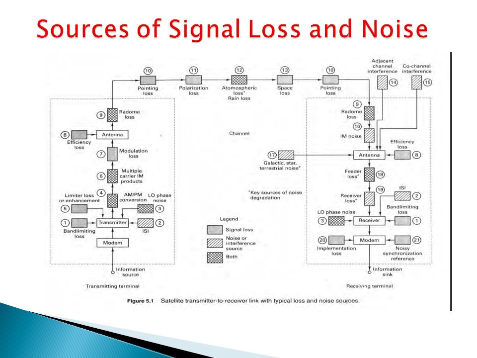
10
Band limiting loss : filters are used in the transmitter to ensure that the transmitted energy confined to the allocated or assigned bandwidth. Such filtering reduces the total amount of energy that would otherwise have been transmitted, the result is loss in signal. ISI : filtering throughout the system in the transmitter, in the receiver and in the channel can result in ISI. Local oscillator phase noise: When LO is used in signal mixing, phase fluctuations or jitter adds phase noise to the signal. AM/PM conversion: Signal amplitude fluctuations produce phase variations that contribute phase noise to signals. Am to PM conversion cause extraneous sidebands resulting signal loss. Limiter loss or enhancement: hard limiter enhances the stronger of two signals and suppress the weaker. Multiple-carrier intermodulation products: Modulation loss: Any power used for transmitting the carrier rather than the modulating signal is a modulation loss. Antenna efficiency: Mechanism contributing to a reduction in efficiency as known as amplitude tapering, aperture blockage, scattering, re-radiation, spillover, edge diffraction and dissipative loss. Radome loss and noise: Radome is a protective cover used with some antennas for shielding against weather effects. Pointing loss: loss of signal when either the transmitting antenna or the receiving antenna is imperfectly pointed Polarization loss: there is a loss of signal due to any polarization mismatch between the transmitting and receiving antennas.

11
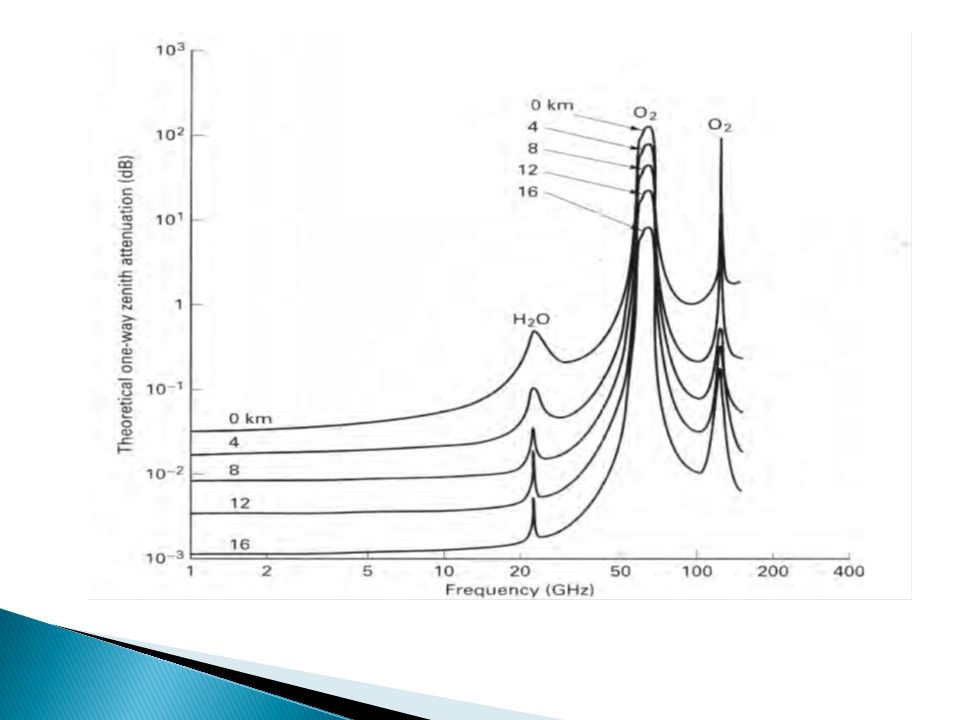
Atmospheric loss and noise : responsible for signal loss and is also a contributor of unwanted noise. Space loss : in satellite communication space loss is the largest singal loss in the system. Radiated energy is not focused on the intended receiving antenna. Adjacent channel interference : characterized by unwanted signals from other frequency channels or injecting energy into the channel of interest. Co-channel interference : refers to the degradation caused by an interfering waveform appearing within the signal bandwidth. Intermodulation noise: active intermods: they can cause a loss in the signal energy or be responsible for noise injected into a link. Passive intermods: caused by multiple carrier transmission signals interacting with non- linear components at the transmitter output. Galactic or cosmic, star and terrestrial noise: all the celestial bodies radiate energy, such noise energy in the field of view of the antenna will degrade the SNR. Feeder line loss: the wave guide or cable(feeder line) between the receiving antenna and the receiver front end contributes both signal attenuation and thermal noise. Receiver loss: Thermal noise generated within the receiver. Implementation loss: it is the loss due to imperfections such as timing errors, frequency offsets, finite rise and fall times of waveforms, and finite value arithmetic. Imperfect synchronization reference: when the carrier phase, the subcarrier phase and symbol timing references are all not derived perfectly results system loss.
 between the receiving antenna and the receiver front end contributes both signal attenuation and thermal noise. Receiver loss: Thermal noise generated within the receiver. Implementation loss: it is the loss due to imperfections such as timing errors, frequency offsets, finite rise and fall times of waveforms, and finite value arithmetic. Imperfect synchronization reference: when the carrier phase, the subcarrier phase and symbol timing references are all not derived perfectly results system loss..")
14
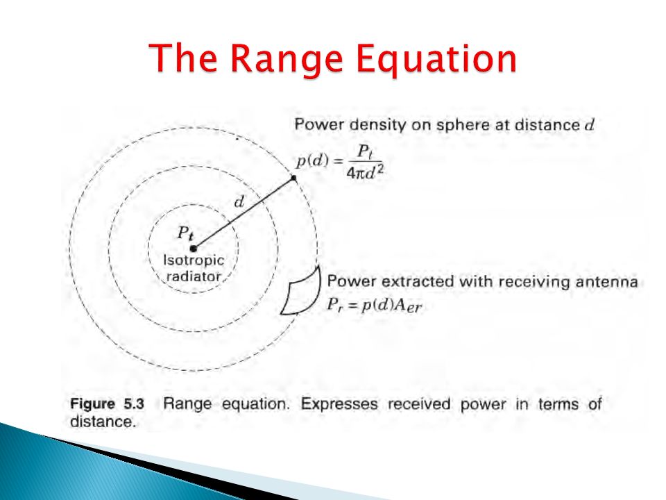
Antennas’s effective area and physical area are related by efficiency parameter Effective radiated power with respect to an isotropic radiator Relationship between antenna gain and effective area is Effective area is calculated by Power received when the receiving antenna is isotropic

15
Transmitting antenna and the receiving antenna can each be expressed as a gain or an area, P r can be expressed four different ways :

17
Caused by thermal motion of electrons in all conductors. Generated in the lossy coupling between an antenna and receiver and in the first stages of the receiver. The noise power spectral density is constant at all frequencies up to about 10 12 Hz, giving rise to White noise. The physical model for thermal noise is a nose generator with an open circuit mean square voltage is 4kT 0 WR The maximum thermal noise power is:

18
In evaluating system performance, the quantity of greatest interest is the signal to noise ratio (SNR). Major concern is the ability to detect signals in the presence of noise with an acceptable error probability. In satellite communication systems, the most usual signal structure is a modulated carrier with constant envelope say, carrier power to noise power ratio as the pre-detection of SNR. For constant envelope signaling the pre-detection SNR is often expressed by using any of the equivalent ratio terms:

Similar presentations


 Professor Honggang Wang>")

>")


 Transmission and Reception>")
