Download presentation
Presentation is loading. Please wait.

1
Suggestion for installation

2
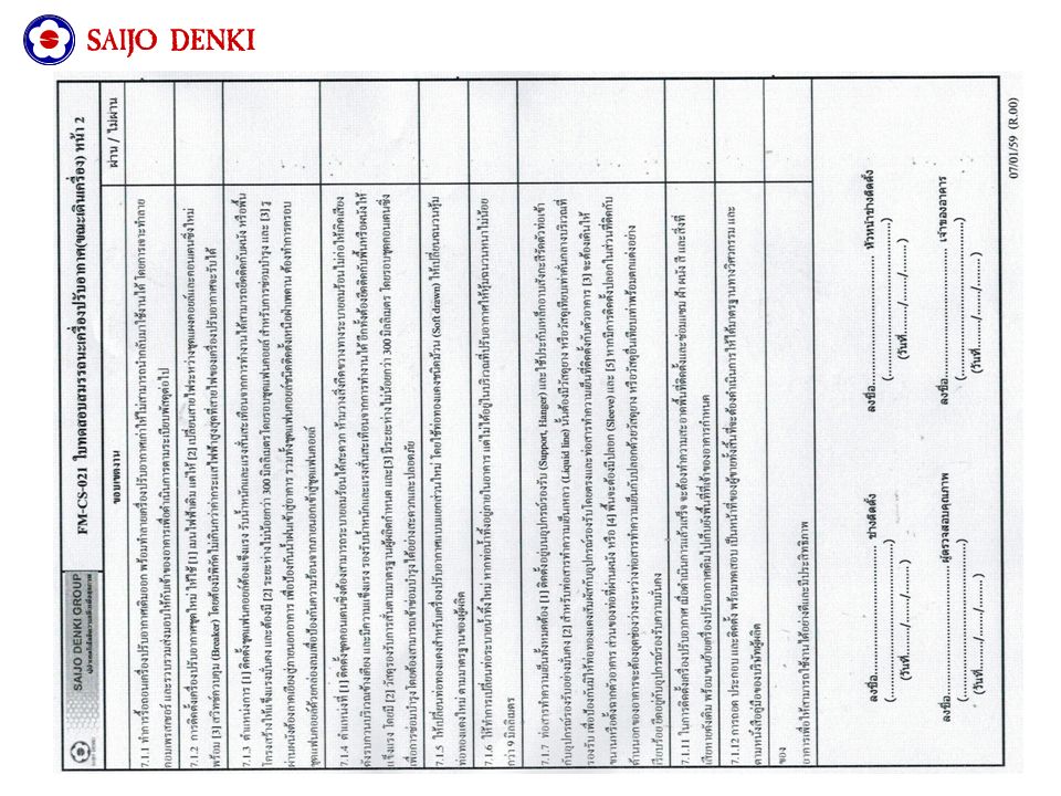
7.1.1 Demolish and destroy the old air condition, then send them to owner building. 7.1.2 Install a new one by last main electrical line. Then change a new wire between coil and condense unit. Use a new compatible breaker. 7.1.3 Choose the position for strong installation. The space around fan coil should be 300 mm. the hole of wall has to incline to the outdoor side to protect raining. 7.1.4 Area for condense unit have to cooling by natural air effectively. And hold to the wall with anti-vibration material. The space around fan coil should be 300 mm. 7.1.5 Change a new coil for spilt type by soft drawn with new insulation as standard. 7.1.6 Change a new drain pipe. If it is in building but it is not in working zone. It have to cover with 9 mm insulation. 7.1.7 All refrigerant pipe have to hold by support with zinc-steel cable fastening. Liquid line pipe have to be on rubber. Don’t contact the equipment directly. Pipe at wall have to cover in sleeve. 7.1.11 After installation, it have to clean and repair the area. Then move the old one to another area follow by owner building. 7.1.12 Removing, installation, testing is the responsibility of vendor follow by standard. Responsibility and duty of installation technician

3
Necessary equipment Flair 1.Flair was use for nut flaring. It’s possible more refrigerant leakage in flair point so choose good standard of flair. 2. Coil cutter was used for resize coil as actual distance. It should choose the good standard for leakage protection. Coil cutter

4
Pressure gauge 3. Pressure gauge was used for measure pressure of refrigerant in system. Vacuum 4. Vacuum equipment was used for removing the air in system ( between cooling coil and hot coil ). Because air have more humidity. It will make cool down in system and make an ice. Finally, it will clog up in system
. Because air have more humidity. It will make cool down in system and make an ice. Finally, it will clog up in system.")
5
Wrench and adjustable wrench Hex wrench 5. Wrench and adjustable wrench was used for nut fastening installation. 6. Hex wrench was used for service vale fastening and openning.

6
Drill 7. Drill was used for concrete drilling. 8. Digital meter was used for electrical measurement. It should be more than 600 VAC of voltage and 100 A of ampere. Digital meter

7
Screw driver LadderBender Temperature and humidity meter Flexible ruler Other Necessary equipment Vise

8
1.Choose area for indoor unit installation 1.1 the area should have more space around air condition about 30 cm. Suggestion for installation

9
1.2 the area for air outlet should be clear. There are no any obstacle in this way for 4-5 meter..

10
2. Choose area for out door unit installation 2.1 the area should have more space around air condition. It should be about 20 cm. and 150 cm. for unit back and unit front, respectively as picture.

11
2. Choose area for out door unit installation 2.2 Out door unit installation have to installed on support over from ground for destroy from raining. And use rubber for anti vibration.

12
2.3 Out door unit installation on wall mounting support, It have to choose strong wall and support.

13
3. Piping 3.1 Use hole saw foe wall drilling. And use cover PVC for insulation and destroy protection.

14
3.2 The length of pipe should be optimum for effective cooling. It’s not less than 2 m.

15
3.3 Good position for cooling and strong for unit weight support. 3.4 Use coil cutter in 90 degree with coil. And it always should to use a new cutter or sharpening

16
3.5 Flairing, nut have to put in pipe before flaring. And flair follow by standard. 3.6 Flaring, pipe have to touch with half in parallel way completely before flair

17
3.7 Tapping should be more fastening for humidity protection.

18
Tapping in the end of line should be held with another glue tape such as black tape.

19
4. Draining pipe 4.1 Draining pipe have to decline down for effective.

20
4.2 If draining pipe was line to waste pipe, It have to use U-trap for bad smelling protection.

21
- The end of drain pipe should be over the water rail for about 3 cm. Don’t merge in the water

22
4.3 Drain pipe should be decline to the outdoor side for water flooding in pipe. - Drain pipe always decline. - If drain pipe don’t decline. Water flooding in pipe will be occurred.

23
Refrigerant diagram and Electrical diagram

24
Indoor unit electrical diagram

25
Out door unit electrical diagram

28
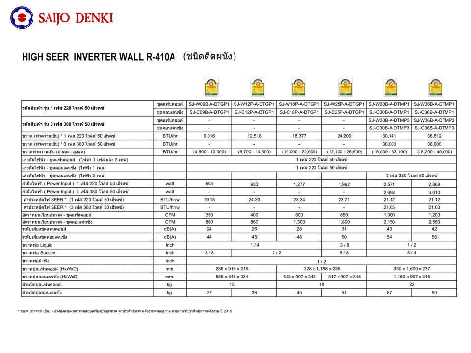
Size of main electrical wire Inverter Fixed speed

29
12000 BTU In door unit wall mount

30
13000 BTU In door unit wall or ceiling mount

31
18000-24000 BTU In door unit wall or ceiling mount

32
36000 BTU In door unit wall or ceiling mount

33
12000-13000 BTU Outdoor unit

34
18000 BTU Outdoor unit

35
25000 BTU Outdoor unit

36
36000 BTU Outdoor unit

37
Wall mount type installation diagram Drain pipe PVC Suction pipe Liquid pipe L (brown) N(blue) Control(orange)
 N(blue) Control(orange)")
38
Wall and ceiling mount type installation diagram Drain pipe PVC Suction pipe Liquid pipe L (brown) N(blue) Control(orange)
 N(blue) Control(orange)")
Similar presentations


 Systems>")


>")


