Download presentation
Presentation is loading. Please wait.

3
Kirk 500 DECT Config (use with systems that require more than 1 Base) Warden Call CO1 CO2 BT Line Wardens Office Telephone Line Panasonic 308 3 Line 8 Extention PBX x 8 Kirk 500 Base 201 202 203 204 205 206 207 208 Kirk Repeater x 6
 Warden Call CO1 CO2 BT Line Wardens Office Telephone Line Panasonic Line 8 Extention PBX x 8 Kirk 500 Base Kirk Repeater x 6")
4
Cabling Kirk 500 DECT Base Station 2. Remove the "break out” at the bottom of the housing by choice. 3. Introduce the cable into the housing. 4. Secure the cable by the attached Cable Bracket and screws. 5. Connect the wires into connector. 1.Remove the PBA from the housing

5
Cabling Kirk 500 DECT Base Station A & B from PBX Ext 1 CH0 CH1 CH2 CH3 CH4 CH5 CH6 CH7 9v PSU RJ45 serial programming connector Kirk 500 Base Using a very thin screwdriver depress pins on the analogue connector and insert the cables from the PBX Extensions.

6
Kirk 500 Base X 6 1 Base 6 Repeaters Max 8 Handsets Max X 8 Kirk 500 DECT Config 1

7
X 6 1 Base 6 Repeaters Max 8 Handsets Max (ONLY 6 X will ring when called) X 8 Kirk 500 DECT Config 2 Kirk 500 Base Repeater Jump Max of 3 Repeater Jumps ONLY
 X 8 Kirk 500 DECT Config 2 Kirk 500 Base Repeater Jump Max of 3 Repeater Jumps ONLY")
8
Base Station In Open Free Space Range = Up to 300M Base Station Inside Building Range = From 50M – 150M Kirk 500 DECT Base Station Range

9
Kirk 500 Repeater Range Repeater In Open Free Space Range = Up to 300M Repeater Inside Building Range = From 50M – 150M

10
Powering the Kirk 500 Base Station & Repeaters 9v DC-DC Convertor 12v PSU (with Battery Back Up) Base Repeater
 Base Repeater")
11
PSU Connection RJ45 Serial programming lead 1. Power up Base Station using PSU 2. Connect Base/Repeater programming lead from PC to the Base/Repeater Registering your Handsets (using CCFP Administration Program) Kirk 500 Base Station
 Kirk 500 Base Station.")
12
Registering your Handsets (using CCFP Administration Program) As soon the program has started to load you can click on the grey field to decide if the program is going to be used via a Direct Connection or as a Modem Connection. It is as well possible to select com port 1 - 4.

13
Registering your Handsets (using CCFP Administration Program) Select Com Port
 Select Com Port")
14
Registering your Handsets (using CCFP Administration Program) Select Direct Connection or Modem Connection
 Select Direct Connection or Modem Connection")
15
Registering your Handsets (using CCFP Administration Program) The Registration form is used for giving serial no. of the handsets and additional user data.

16
Registering your Handsets (using CCFP Administration Program) Users can be deleted or moved to other channel/IWU
 Users can be deleted or moved to other channel/IWU")
17
Registering your Handsets (using CCFP Administration Program) User data is written here!
 User data is written here!")
18
Registering your Handsets (using CCFP Administration Program) The CCFP Set-up form is used for setting up IWU parameters to match the parameters of the connected PABX and/or eventually PSTN line.
 The CCFP Set-up form is used for setting up IWU parameters to match the parameters of the connected PABX and/or eventually PSTN line.")
19
Registering your Handsets (using CCFP Administration Program) Global Set-up Individual IWU card Set-up
 Global Set-up Individual IWU card Set-up")
20
Setting up DTMF duration on the Kirk 500 Base to allow Warden Call use This MUST be carried out using the CCFP Administration Program Change this Value to 150ms

21
Registering your Handsets onto the Kirk 500 Base Station (after Registration with CCFP Administration Program) 1. Connect Power to your Kirk 500 Base 2. The Handset should be located close to the Base Station. 3. On the Handset Press the ‘Menu’ key. 5. Press the Left arrow key < twice. 6. The menu will now show ‘Login’ 7. Press the TICK key – the menu will show, ‘Select Login’ 8. Press the right arrow key > once then press The TICK key – the menu will now show: Subscription search I.D. The handset will start searching for ‘your’ Base.

22
When the handset finds a system, a number will appear in the display. It is important that the number shown is identical to the number which you find on the rear of the Base. The number is indicated as an ARI. (The number should start with 00077 for Kirk) Then Enter AC No: 0000 and press TICK key. Registering your Master Handset onto the Kirk 500 Base Station (after Registration with CCFP Administration Program)
 Then Enter AC No: 0000 and press TICK key. Registering your Master Handset onto the Kirk 500 Base Station (after Registration with CCFP Administration Program).")
23
1. Press the ‘Menu’ key 2. Press the > arrow key once. 3. The menu must now show ‘EXT. Service’ 4. Press the ‘Tick’ key. The menu will now show ‘Clip Stack’ 5. Press the < arrow key twice until ‘Read/Write userdata’ appears in the display. then press the ‘Tick’ key. 6. The Serial Number of the MASTER handset will now show in the display If you press the > arrow key, you will have additionally 7 positions (Channel 01 – 07) in which you can configure handsets. Registering additional Handsets via your Master Handset
 in which you can configure handsets. Registering additional Handsets via your Master Handset.")
24
7. If the position is empty, the display will show the following:’________________’ 8. You can now enter the Serial Number of the new handset (found inside the handset under the battery, on the label) followed by the ‘Tick’ key. Right after this has been done, the handset will ask for an Extension Number. Simply enter the Extension Number the handset is going to use (e.g 202) followed by the ‘Tick’ key. The MASTER handset has now ‘allowed’ the system to register the new handset to the system. You can now register the handset/s in the same way as was done when registering the MASTER handset. Registering additional Handsets via your Master Handset cont ………
 followed by the ‘Tick’ key. Right after this has been done, the handset will ask for an Extension Number. Simply enter the Extension Number the handset is going to use (e.g 202) followed by the ‘Tick’ key. The MASTER handset has now ‘allowed’ the system to register the new handset to the system. You can now register the handset/s in the same way as was done when registering the MASTER handset. Registering additional Handsets via your Master Handset cont ……….")
25
Kirk Handset DECT Config Important codes for Handset configuration: Phone ONHOOK: *99981* then Tick Key = Q52 & RSSI 64 values (for survey use) Phone ONHOOK: *99982* then Tick Key = Displays Handset S/ware Phone ONHOOK: *99984* then Tick Key = Displays Handset Serial Number Phone ONHOOK: *99956* xx (where xx is the new number of low RSSI quality measurement) This is to adjust the number of times a low quality RSSI is measured for quicker change over between system/Bases. Phone ONHOOK: *99955* xx MUTE (where xx is the new value in decimal This is to adjust the RSSI quality value to initiate quicker change over between systems/bases. Phone ONHOOK: *99973* xx MUTE (where xx is the new value in decimal) This is to adjust the Q-Value to initiate quicker change over between systems/Bases
 This is to adjust the Q-Value to initiate quicker change over between systems/Bases.")
26
Registering Repeaters onto the Kirk 500 Base Station PSU Connection RJ45 Serial programming lead 1. Power up Repeater using PSU 2. Connect Repeater programming lead from PC to the Repeater Repeater

27
Registering Repeaters onto the Kirk 500 Base Station Firstly set up Comms port And Baud Rate

28
Base Station ARI No (i.e 00077 0446678) :SPACE Repeater No. Base or Repeater to synchronize on Registering Repeaters onto the Kirk 500 Base Station

30
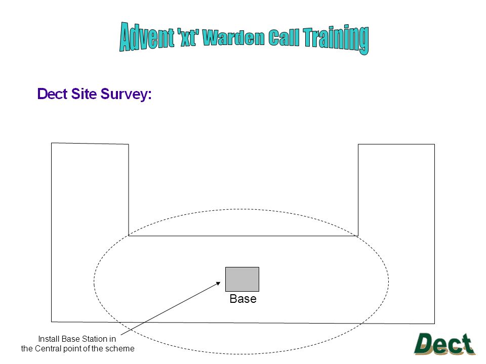
Install Base Station in the Central point of the scheme Base

31
Keep walking until you are out of range With a Subscribed Handset ‘on-hook’, enter code *99981* and press the TICK key. The Handset display will show the signal quality in the following way: RPN:01 Q52:52 (speech quality) RSSI:64 (signal strength) Take the Handset ‘Off Hook’ as this will ensure more accurate figures and you can personally check the audio quality. It is good practice to listen to the audio source and view the handset at the same time.
 RSSI:64 (signal strength) Take the Handset ‘Off Hook’ as this will ensure more accurate figures and you can personally check the audio quality. It is good practice to listen to the audio source and view the handset at the same time..")
32
Base Keep walking until you are out of range Check the boundaries of the coverage area, this can be defined as where Q52 is greater than 52 and RSSI is greater than 64. Repeat this process with the Survey Base Station in a new location. Check that the overlap between coverage areas is at Least 10 metres.

33
10m Base Out of range Of the Base Station

34
10m Base Out of range Of the Base Station 10m Out of range Of the Base Station Repeater/Base signal overlap

Similar presentations


 Sussex County Public Schools.>")


 EXP1240 Series IP DECT Cordless System for Mobility EXP1240 Series.>")


>")


![Multiconn Srl PORSCHE PCM3.0 – PCM3.1 www.dasdvbt.com Installation and User Manual ver.1.0 [to integrate with the user manual of DAS M32/M44] [to integrate.](/14/4475311/big_thumb.jpg "Multiconn Srl PORSCHE PCM3.0 – PCM3.1 www.dasdvbt.com Installation and User Manual ver.1.0 [to integrate with the user manual of DAS M32/M44] [to integrate.>")
 How to Find Positions within Your Organizational Unit Prepared by Student Employment Services November 2007.>")

