Download presentation
Presentation is loading. Please wait.

1
Embedded system design issues

2
Embedded system design requirement n Real-time, reactive n Small size, low weight n Low power, limited cooling n Safe and reliable n Extreme cost sensitivity

3
Real-time operation n Real-time: correctness of result is a function of time it is delivered –Not necessarily ‘real fast’: predictability is the issue –Worst case performance often limits design n Reactive: computation rate is in response to external events –Periodic events can be scheduled statically –Aperioidc events must be statistically predicted, and dynamically scheduled when possible n Design challenges –Least pessimism in worst case analysis –Accurate performance prediction

4
Small size, low weight n Embedded computers are embedded in something –Form factor may be dictated by aesthetics –Form factor may be carry-over from previous system –Limited resources (memory, LCD, …) n Weight may be critical –Comfort for carried object –Fuel economy for transportation n Design challenges –Integrating digital + analog + power on single chip –3-D geometries
 n Weight may be critical –Comfort for carried object –Fuel economy for transportation n Design challenges –Integrating digital + analog + power on single chip –3-D geometries")
5
Safe and reliable n Systems must be safe to protect people & property –Mission critical systems –Regulations n Reliability –Critical to customer (e.g. phone call hand-over) –Traditional fault-tolerant method is expensive –High availability may come at the cost of reliability n Design challenges –Realistic reliability prediction –Low-cost reliability
 –Traditional fault-tolerant method is expensive –High availability may come at the cost of reliability n Design challenges –Realistic reliability prediction –Low-cost reliability.")
6
Harsh environment n Many embedded systems do not have controlled environment –Heat from combustion / limited cooling –Vibration / shock –Water / corrosion –Fire –Shipping damage –Physical abuse (drop test) –Dirty power supply –Lightning / electro-magnetic interference
 –Dirty power supply –Lightning / electro-magnetic interference")
7
Cost sensitivity n Component cost is visible to engineer –Sometimes wrong thing to optimize for –Cost vs. robustness –Life-cycle optimization

8
System level design issues

9
System-level requirements n End-product utility is the goal n System safety & reliability n Analog & I/O n Power management

10
End-product n Products sold on the basis of cost & features –Feature-list wars –Fad tech. (e.g. fuzzy-logic rice cooker) n S/W differentiates the system –I/O defines the interaction –S/W defines the functionality & quality of interaction n Design of CPU or digital H/W is not the first step in the design
 n S/W differentiates the system –I/O defines the interaction –S/W defines the functionality & quality of interaction n Design of CPU or digital H/W is not the first step in the design.")
11
System safety & reliability n S/W can invite complexity –Complexity invites problems –Traditional fix: use H/W instead of S/W, but it does not work for dynamic environment n Reliability is cost –A single fault may cause mass recall –Wrong design induces large maintenance cost

12
Analog I/O n Analog I/O is where work gets done n Computer-aided design seldom support analog components n Trend: use of smart sensors –Small CPU on each remote component does A/D, D/A conversion –Networks with embedded components n Design the system considering debug functionality –Simulation & rule checking for mixed digital/analog systems

13
Power management n Power is limited due to heat or power storage capacity n Low power desktop CPUs are not really suitable for embedded systems –Low power Pentium: 3 ~ 7 W –PDA: less than 1 W –Less than 1 mW for many systems (e.g. Casio data watch) n Design issues –Low-power operation –Fast wake-up –Low-cost power generation
 n Design issues –Low-power operation –Fast wake-up –Low-cost power generation.")
14
Choosing an OS n License fee –Critical for embedded systems e.g. Suppose 1$ for 1 piece. If we sell 1M pieces, it costs 1M$ n H/W support –Is there an efficient tool for debug? –How about the device drivers? n Developer support –How expensive is the development tools? n Reliability n Upgrade

15
Choosing an OS n Networking support –usually the programmer should do it n File system support –Flash file system –NFS –XIP n Software size –Often critical to cost –Sometimes you should abandon some features

16
Real-time multitasking executives 1. 개관 2. 커널의 구성

17
1. 개관 RTOS 실행체제 멀티태스킹 기법 태스크

18
하드웨어 특성의 추상화 범용 운영체제를 포함한 모든 운영체제 시스템의 기본적 인 기능

19
예측 가능한 문맥 전환 n 실시간 시스템 “ 시간에 맞게 ” 올바른 결과를 전달하는 시스템 n 시스템 사용 전에 시스템 분석 가능 여부가 매우 중요 n 다양한 정적 분석에 대하여 기능적, 시간적 행동 양식이 충분히 결정적이고 예측 가능해야 함. 실시간 운영체제들은 실시간 태스크를 처리함에 있어서 제한되지 않는 문맥 교환 지연을 발생시키지 않아야 함.

20
RTOS 의 네 가지 필요 조건 1) ( 완전 ) 선점형 커널을 제공 2) 우선 순위 기반의 스케줄링 제공 3) 인터럽트 지연시간이 일정 범위 이내여야 함 4) 스케줄링 지연시간이 일정 범위 이내여야 함
 ( 완전 ) 선점형 커널을 제공 2) 우선 순위 기반의 스케줄링 제공 3) 인터럽트 지연시간이 일정 범위 이내여야 함 4) 스케줄링 지연시간이 일정 범위 이내여야 함")
24
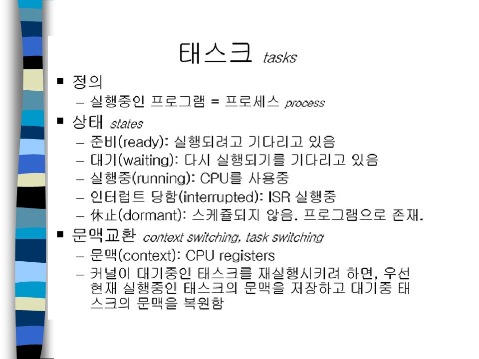
멀티태스킹 n 태스크 - 응용 프로그램의 실행가능 한 기본단위, 설계 단위 - 수행 중단 뒤 재시작 가능하도록 런타임 문맥을 가짐 - 상태 천이 가능 - DART 등을 이용하여 시스템 설계 단계에서 추출가능 n 멀티태스킹 - 태스크들을 CPU 상에서 스케줄링하고 전환하는 과정 - 응용 프로그램의 동시성 증가로 인해 CPU 이용율 증가

26
멀티태스킹 n 무한 폴링 – 장점 간단한 내장형 응용프로그램의 경우 효과적 RTOS 의 멀티태스킹 능력에 의존하지 않으므로 효과적 – 단점 많은 CPU 이용율이 폴링 루프에서 불필요하게 낭비 한 이벤트의 최대 응답시간은 폴링 루프의 총 수행시간으로 결정

28
멀티태스킹 n 인터럽트 대응 – 폴링 루프로부터 실시간 이벤트들을 분리함으로써 부분적 문제점 해결가능 ex) 하드웨어 인터럽트 대응 – 이벤트 처리가 과도할 경우, 인터럽트 없는 폴링 루프와 마찬가지임. 태스크 기반 설계 방법 및 멀티태스킹 실시간 커널 필요

29
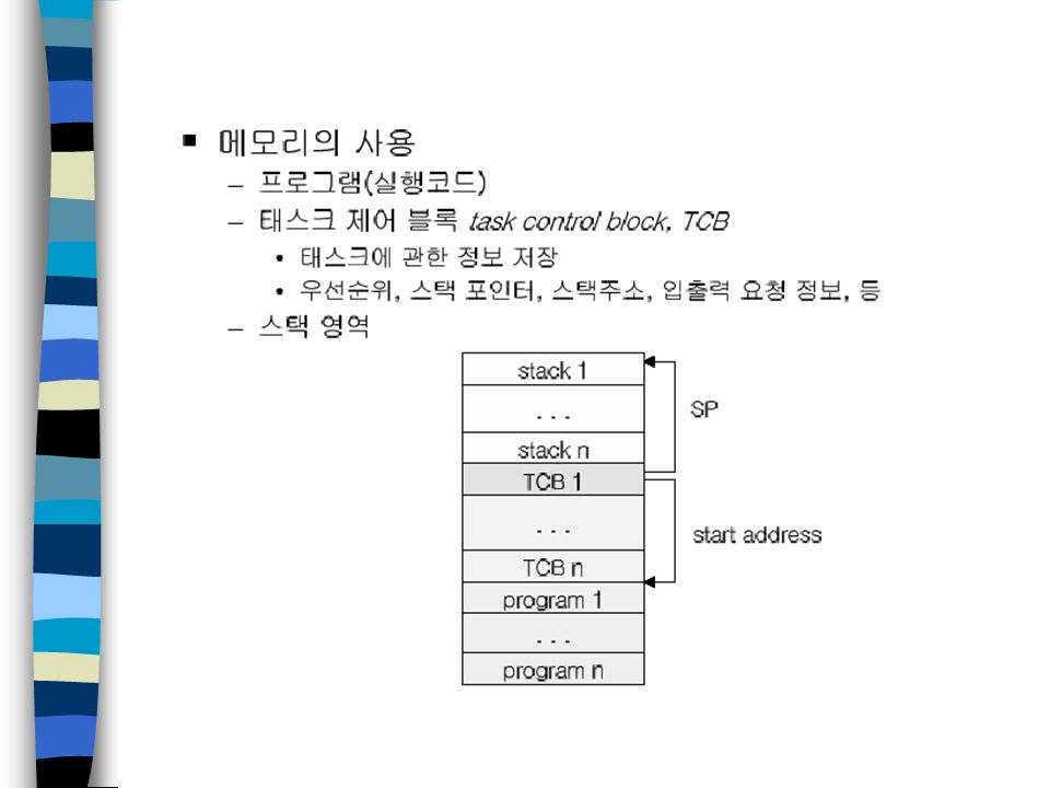
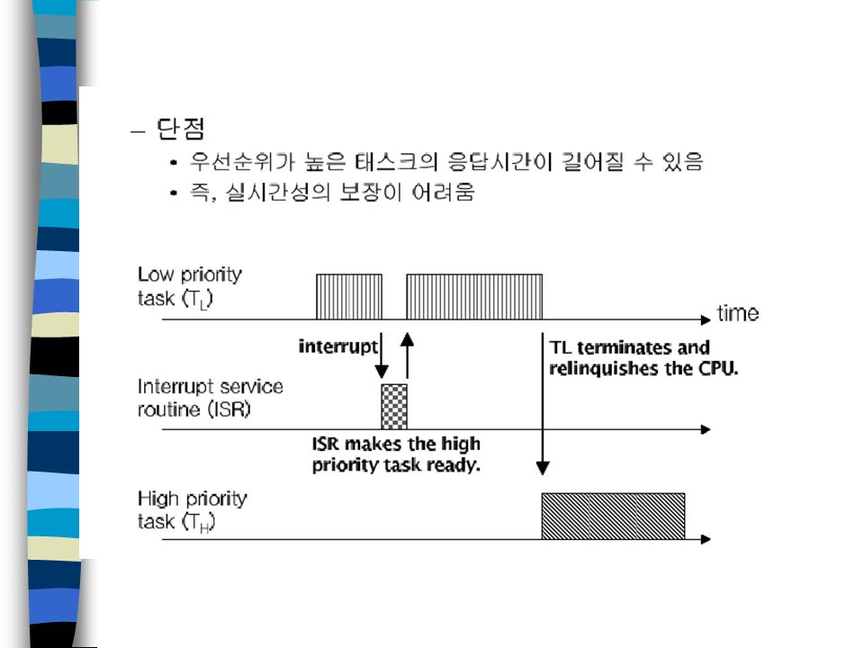
멀티태스킹 n 멀티태스킹 실시간 커널 – 수행 중 태스크의 문맥을 저장하고 복구하는 기능 필요 – 태스크 문맥을 스택에 저장하고 새 태스크의 문맥을 스택으로부터 복 구함으로써 태스크 문맥 전환 수행 – 태스크는 중요도에 따라 우선순위를 가짐 – 선점형 커널과 비선점형 커널로 구분 시스템 응답 시간 이 중요한 경우 선점형 커널 사용

33
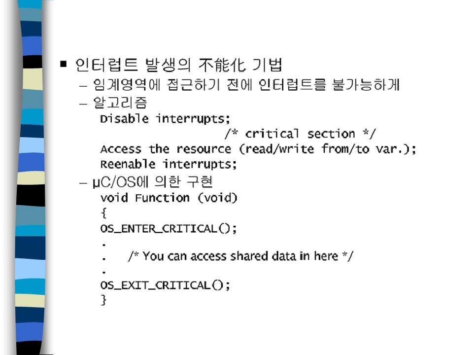
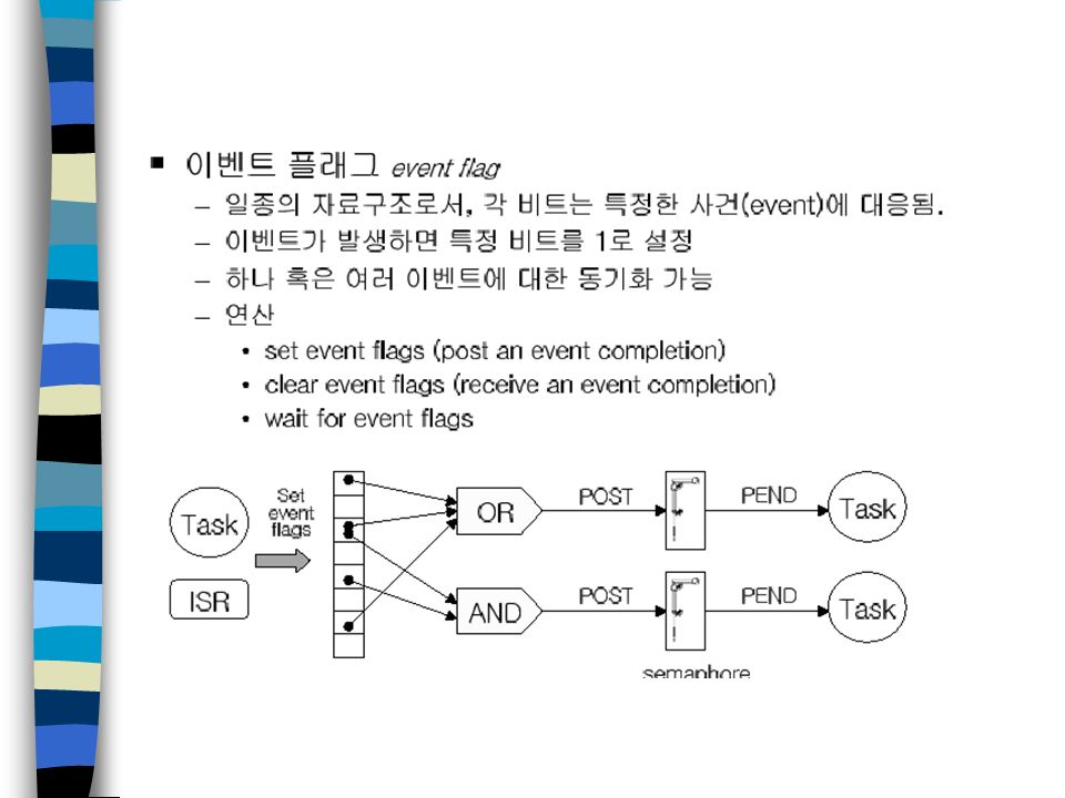
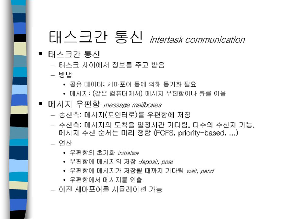
2. 커널의 구성 커널, 상호배제, 동기화, 태스크간 통신, 인터럽트 처리

44
세마포어

58
S/W configuration

59
Selecting a compiler n Build or buy? –Depends on the system If you have a DSP, you may have to use the compiler provided by the vendor You can build a cross-compiler by yourself –Open source? If you have source codes of compiler, you can do many things n Usual tools –GNU tools –ARM Developer Suite (ADS) –Third party tools
 –Third party tools.")
60
Building a cross-compiler n GNU tools –You can find information: www.armlinux.org/docs/toolchain for arm penguippc.org/usr/embedded/howto/PowerPC-Embedded- HOWTO.html for PowerPC –toolchain gcc glibc gdb binutils –Some targets may not be supported Especially when the target has DSPs You should modify the source codes

61
Example: porting GCC n Writing back-end for the “machine” –Target description macro (machine.h) Endian, bits per word, pointer size, etc. –Machine description (machine.md) Description of machine codes in RTL n Configure –Tools (as, ld, ar, ranlib) for the cross-compiler –Libraries: crt0.o, libgcc1.a, etc. n Make gcc
 Description of machine codes in RTL n Configure –Tools (as, ld, ar, ranlib) for the cross-compiler –Libraries: crt0.o, libgcc1.a, etc. n Make gcc.")
62
Configuration of modules n Memory layout should be defined –Various configuration e.g. 16MB flash + 4MB RAM + 1MB internal SDRAM Often restrict functionality & debugging –Memory layout should be given at link time –Developer should determine which module will be in a certain memory n Use of MMU –Most embedded systems do not use MMU No virtual memory, only physical memory How can we protect memory address space?

63
Example memory layout (typical ARM).code.data.bss System stack ISR stack Application memory can be transferred at boot time ROM RAM
.code.data.bss System stack ISR stack Application memory can be transferred at boot time ROM RAM")
64
Testing and debugging

65
Test on host computer as much as possible n Access to debugging tools –Usually we have better debugging tools on host computer than the target n Simpler debugging cycle –Save downloading time –Easy to look the problems n Different environment –It is important to have effective simulation tools –It may take time & cost to develop simulation environment

66
Debugging tools n ARMulator –Software emulator of the ARM processor –Components Processor core model Memory interface Co-processor interface OS interface –Symbolic debugger: ARMsd –It is possible to build a complete, clock-cycle accurate software model –Initial evaluation of design –You must check you can use an emulator depends on the chip vendor

67
Debugging tools n OS-level simulator –Independent of H/W –Used to check the behavior of applications on OS –You may need to port all the assembly codes & drivers

68
Debugging tools n JTAG boundary scan test Architecture –Standard interface (5-pin serial protocol) IEEE 1149 –Access and control the signal levels on the pins of a digital circuit –Principal goal – PCB, VSLI testing n Embedded-ICE –Standard solution for ARM debug architecture –Based on the JTAG test port –Can set breakpoints & watchpoints
 IEEE 1149 –Access and control the signal levels on the pins of a digital circuit –Principal goal – PCB, VSLI testing n Embedded-ICE –Standard solution for ARM debug architecture –Based on the JTAG test port –Can set breakpoints & watchpoints")
69
ARM7 debug system

70
Scan chains in ARM core Test Access Port

71
Debugging tools n Embedded trace –Basically, printf See what happens in the S/W modules –Real-Time Trace? Limited bandwidth between the target & the host Trace should not interfere the running of the target It is hard to get “real” real-time trace

Similar presentations