Download presentation
Presentation is loading. Please wait.

1
The General Electric T-700
Or What makes that “Rotor Thing” turn? CW3 SMART References: -10 T700 Engine manual Student Handouts

2
OBJECTIVE Develop student instructor pilots understanding of the GE T-700 engine.

3
Topics History and development IAW FTG Schedule
Electrical control unit (ECU) Hydromechanical unit (HMU) Pressure and overspeed unit (POU) NP overspeed protection Engine Alternator
 Hydromechanical unit (HMU) Pressure and overspeed unit (POU) NP overspeed protection. Engine Alternator.")
4
ENGINE CHARACTERISTICS
Output power: 1,543 SHP (sea level standard day) Type of compressor: 5 stages axial, 1 centrifugal Variable geometry: IGV+ stage 1&2 stator vanes Engine weight: 415 LBS Time between overhaul: none(on condition)
 Type of compressor: 5 stages axial, 1 centrifugal. Variable geometry: IGV+ stage 1&2 stator vanes. Engine weight: 415 LBS. Time between overhaul: none(on condition)")
5
HISTORY&DEVELOPMENT The T700 engine design is directed at minimizing required maintenance Maintenance tasks have been simplified Corrective maintenance is on on a “on condition” basis Modular design allows sub-system replacement

6
HISTORY CONTINUED: Lock wire elimination Tool requirements reduced
LRU’s External lines reduced HMU no Rigging Dual sided sight glass and “impending” bypass indicators

7
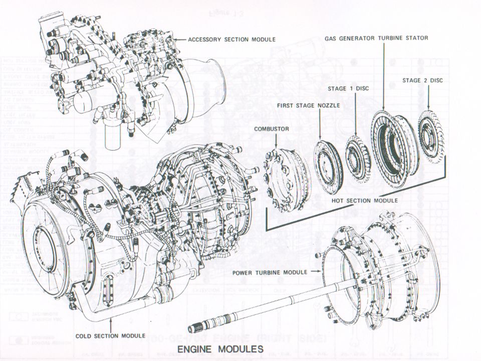
ENGINE MODULES Cold section Hot section power turbine module
Accessory module

9
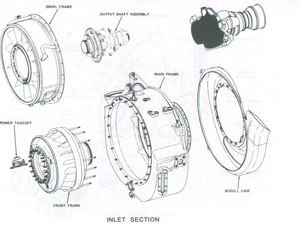
COLD SECTION

10
COLD SECTION Includes the inlet comprised of , swirl frame, main frame, front frame, and scroll case. These together with the inlet duct and blower make up the Inlet. Compressor section, diffuser and midframe. Hot air and oil provide anti-icing Scroll vanes act as air/oil cooler supplementing the fuel/oil cooler 100% NG=44,700 RPM

12
BASIC OPERATION

13
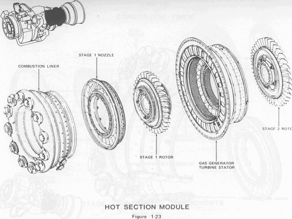
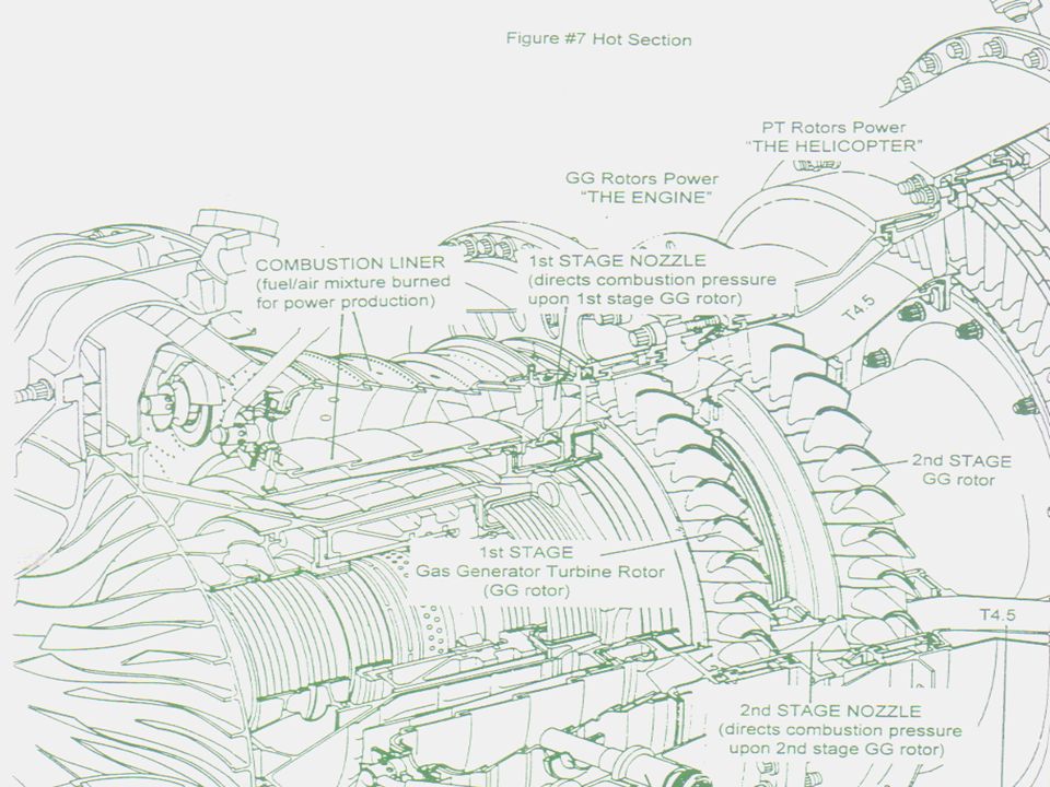
HOT SECTION Consists of combustion liner, #1 stage nozzle assembly, and the gas generator turbines. Gas generator turbines rotor drives the compressor 12 fuel injectors, 2 primer nozzles, and 2 igniters

17
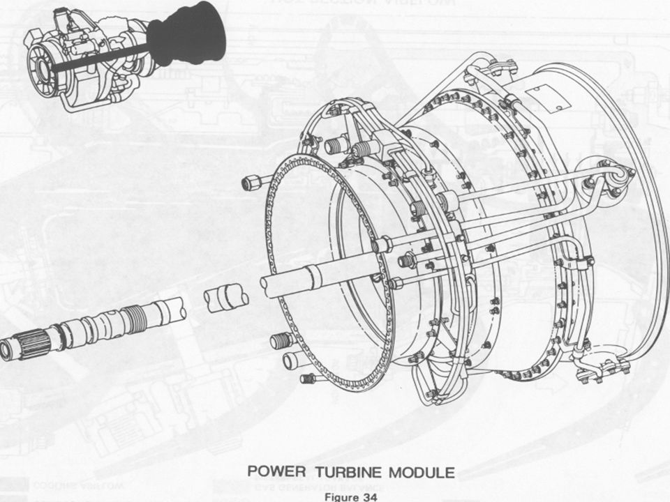
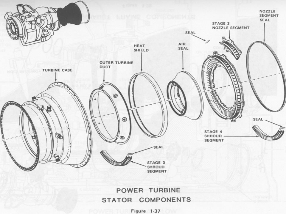
POWER TURBINE MODULE Comprised of the power turbine rotors, power turbine driveshaft, power turbine case, the #3 and #4 nozzles, and the exhaust frame. Expanding exhaust gases exiting drives the free power turbine at 20,900 RPM=100%NP Casing support the 7 TGT Thermocouples and the NP/torque sensors

22
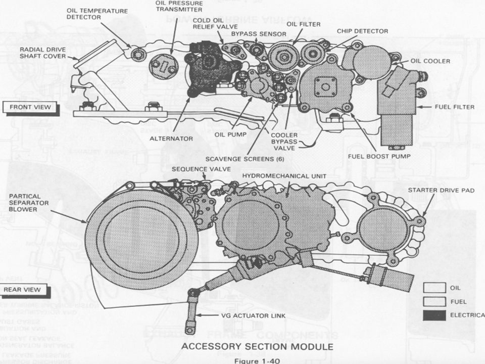
ACCESSORY MODULE Mounts to the cold section module and is driven off the compressor section by a PTO via a radial driveshaft. Provides drive and mounts (pads) for engine components
 for engine components.")
24
ECU

25
ECU….. WHAT’S IT DO? Trims the HMU NG governor through the tq motor within acceptable engine limits to maintain isochronous NP governing. This can be overridden ONLY by TGT limiting. Exchanges tq signals to provide automatic load sharing for multi-engine use. Provides signal to the POU for NP overspeed protection % Provides cockpit signals, NP, TGT, TQ

26
ECU FUNCTIONS, OR CHECK RIDE ANSWERS ?
Np reference from cockpit Overspeed signal to POU (redundant power,TQ SIGNAL) TGT limiting, Signals to cockpit, TQ, TGT, Np History recorder signal Isochronous NP governing(will maintain ref.) Torque load sharing
 TGT limiting, Signals to cockpit, TQ, TGT, Np. History recorder signal. Isochronous NP governing(will maintain ref.) Torque load sharing.")
28
HYDOMECHANICAL UNIT

29
HMU DESCRIPTION Mounted on the aft center of the AGB
Receives filtered fuel through cored passages in the AGB High pressure vane type pump. Max 832 PSI

30
HMU FUNCTIONS Collective pitch compensation (LDS)
Acceleration/deceleration flow limiting Ng limiting (Governing & shutdown) Torque motor to trim NG governor PAS override (lockout) Fuel pumping Fuel metering Variable geometry positioning Vapor vent (priming)
 Torque motor to trim NG governor. PAS override (lockout) Fuel pumping. Fuel metering. Variable geometry positioning. Vapor vent (priming)")
31
POU

32
POU DESCRIPTION The Pressurizing and overspeed unit is mounted on the aft, left hand side of the AGB 3 outlets. Start fuel manifold, main fuel manifold, and overboard drain (+bypass during overspeed) 3 inlets. Fuel through AGB core, P3 air, overspeed signal
 3 inlets. Fuel through AGB core, P3 air, overspeed signal.")
33
POU FUNCTIONS Sequences fuel to start fuel manifold (2)
Sequences fuel to main fuel manifold (12) Purges start fuel manifold and nozzles during start, and main fuel manifold and nozzles during shutdown Provides NP overspeed protection when activated from the ECU overspeed circuit
 Purges start fuel manifold and nozzles during start, and main fuel manifold and nozzles during shutdown. Provides NP overspeed protection when activated from the ECU overspeed circuit.")
34
ENGINE ALTERNATOR

35
ALTERNATOR DESCRIPTION
Mounted on the right hand forward side of the AGB Provides power to all essential engine functions output consists of 3 individual signals (windings) May fail independently or as a unit
 May fail independently or as a unit.")
36
ALTERNATOR FUNCTIONS (BY WINDING)
Provides power to the ignition exciter Provides power to the ECU Provides NG signal to the cockpit

37
NICE TO KNOW STUFF BLUE=OVERSPEED GREEN=COCKPIT SIGNALS
BLACK=ENGINE IGNITION YELLOW=ENGINE ELECTRICAL FUNCTIONS

38
ENGINE EP’S FAILURE LAUNDRY LIST COMPRESSOR SHAFT
INCREASE/DECREASE/TQ SPLIT

40
LIMITS OIL TEMP OIL PRESS NG NP TGT / 20-100/35-100 0-99/99-102/ 91/95-101/ / 0-775/ /

41
SUMMARY The T700 is closely integrated with helicopter components to provide proper power output for each flight condition The system functions automatically, with no pilot action required after starting Engine control is functionally split between the HMU and ECU. The HMU provides functions for safe operation, and the ECU performs a fine trim to reduce pilot workload The system is self contained and engine powered

Similar presentations