Download presentation
Presentation is loading. Please wait.

2
Moxon Beams Design & Building by WB5CXC 2006 Ham - Com

3
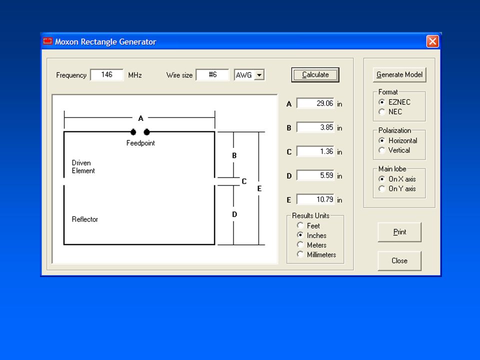
Moxon Beam Invented by Les Moxon – G6XN Program Design by Dan Maguire AC6LA from formulas from L.B. Cebik W4RNL Download Moxon Generator program: –www.moxonantennaproject.com/design.htm

4
Moxon Beam cont’d Two Element Folded Beam –Reduced size 50 Ohm Impedance (no matching required) –Elevations above ½ wavelengths have very little effect on SWR ~ 5.5 - 11 dB gain Front to Back Ratio - ~ 25 – 30 dB
 –Elevations above ½ wavelengths have very little effect on SWR ~ dB gain Front to Back Ratio - ~ 25 – 30 dB")
5
Moxon Beams cont’d Easy to Build –Can be made from wire or alum. Tubing –PVC, Wood, Fiberglass Design Program –Put in the frequency & size of wire/tubing –Dimensions will be calculated

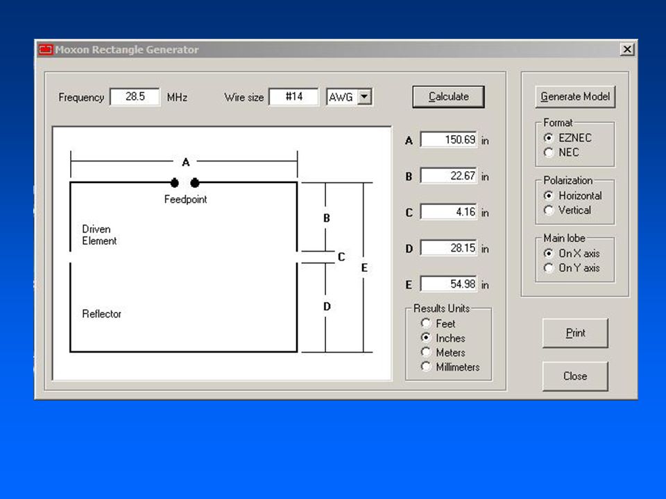
6
Moxon Beams cont’d Need to download MoxonGenerator.exe –This is the design program Put in the center frequency you intend to operate and the wire or tubing size –Hit calculate – program will calculate the dimensions and spacing

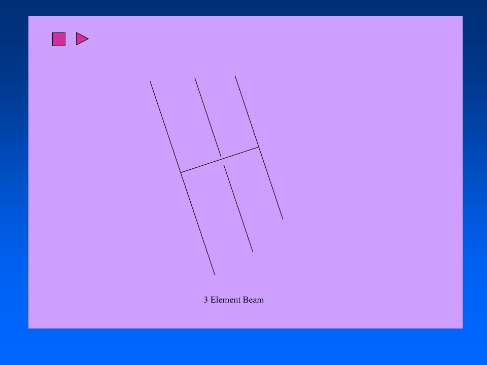
7
Generate Model for Antenna Modeling Program

8
Beams in General Beam antennas come in all different designs The most common is the straight element Yagi –2 – 4 element in HF bands –Many elements in the VHF, UHF bands The length of the elements and the boom are inversely proportional to the frequency –The lower the frequency the longer the elements and boom

11
Building Moxon Beams Design your Moxon Beam Measurements are critical as well as the wire or tubing used. If you are using different wiring or tubing size – recalculate for the different size of wire/tubing. The Elements are isolated from ground and each other.

12
Building Moxon Beams cont’d Design a Moxon Beam for 10 Meters Center frequency will be 28.5 Mhz We will use # 14 wire

16
1 ¼” Tee 1 ¼” X ¾” Reducer 45 Elbow

17
-12 dB ~ -22 dB

21
R = Resistive X = Impedance (capacitance or inductance) X – when it is too long or too short or other interactions – on some antennas it might not ever be 0. At Design X = 0

22
What does all this Mean? This data was generated using an Antenna modeling program (MultiNec & Eznec) Antenna is modeled at 20 feet above ground, with average Ground conditions, and copper wire. Modeled antenna is compared to ½ dipole (usually) Can also be model in free space.
 Antenna is modeled at 20 feet above ground, with average Ground conditions, and copper wire. Modeled antenna is compared to ½ dipole (usually) Can also be model in free space..")
23
What does all this Mean? cont’d Gain 10.9 dB –dB = 10 log (P out / P in ) Gain is the number that corresponds to a log 10 of 1.09 Gain is 12.3 (compared to ½ wave dipole) –You get 12.3 time the power in the main direction as compared with a ½ wave dipole
 Gain is the number that corresponds to a log 10 of 1.09 Gain is 12.3 (compared to ½ wave dipole) –You get 12.3 time the power in the main direction as compared with a ½ wave dipole.")
24
dB numbers that you should know 3 dB Double Power or ½ Power 10 dB – 10 times Power or 1/10 Power 20 dB – 100 times Power or 1/100 Power

25
What does all this Mean? cont’d Fr/Rear is 10.5 dB This is a ratio of 11.22 Signals coming in from the rear has a reduction of 1/11.22 F/Back is ~ 23 dB Signals are reduced by 1/199.5

26
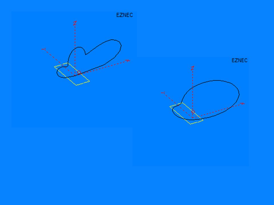
Antenna Pattern – for the different frequencies - Pattern in horizontal plane – notice the beam width Beam Width where signal is reduced by 3 dB Beam Width + 37 degrees 74 degrees 3 dB circle

27
Antenna Pattern for the different frequencies Pattern in vertical plane Elevation Angle

30
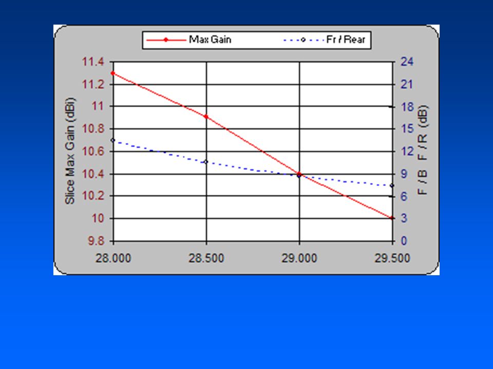
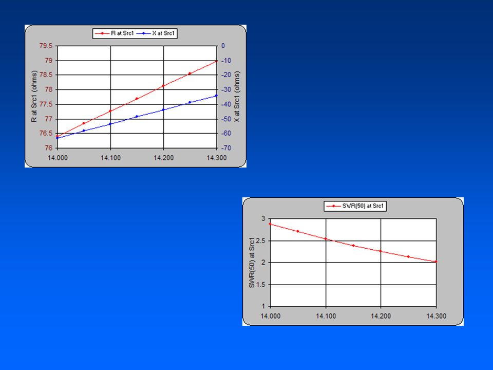
SWR curve – with a tuner you could operate 28 to over 29.5 Mhz

31
With any antenna the feed point is usually reactive Made up of resistance and impedance.

33
2M Vertical Polarized Moxon Antenna 29” tall - 11” wide Using #6 copper wire My First Moxon

34
Cost Material Cost for 2M Moxon #6 Bare Copper wire - $ 2.75 1/2” PVC Tees $.83 10’ 1/2” PVC Pipe $ 1.29 Total $ 4.87

35
Blue – 146 Mhz – Design Red – 148 Mhz ~ -36 dB F/B Ratio Notice: Beam Width – ~ 140 degrees

36
Covers entire 2M band

39
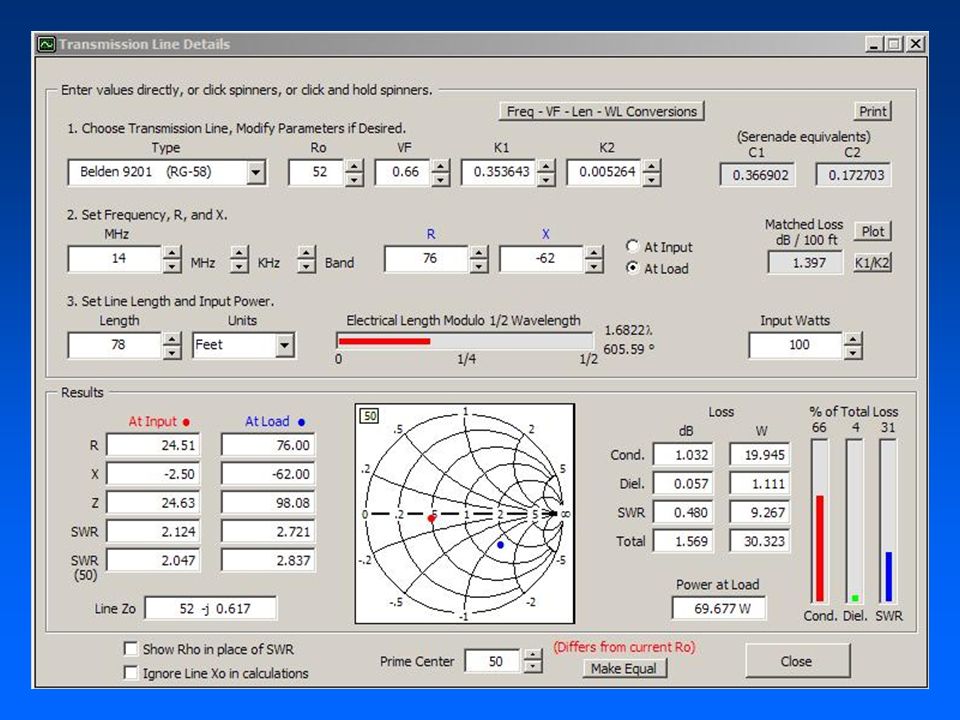
Maximum transmitted power to the Antenna

40
This system has a large SWR – what do we normally do? SWR = 2.8

42
This matches the Transmitter (50 ohm) to the transmission line / antenna and makes the transmitter happy.
 to the transmission line / antenna and makes the transmitter happy.")
44
Moxon Programs & Etc. Moxon Antenna Design Program –http://www.moxonantennaproject.com/design.htmhttp://www.moxonantennaproject.com/design.htm Transmission Line Analyzer Program – TLDetails (Freeware) –http://www.ac6la.com/http://www.ac6la.com/ Excel Based Antenna Modeling Program – MultiNec –http://www.ac6la.com/http://www.ac6la.com/
 – Excel Based Antenna Modeling Program – MultiNec –")
45
Moxon Programs & Etc. Eznec Antenna Modeling Program –http://www.eznec.com/http://www.eznec.com/

Similar presentations


 and an Open Wire Fed Dipole (OWFD)>")


 Used for all mathematical calculations in the radio world. – dB is a logarithmic number dB =10.>")
