Download presentation
Presentation is loading. Please wait.

1
Vacuum tank relief for Super-FRS long multiplet cryostat CrYogenic Department in Common System (CSCY) GSI, Darmstadt Yu Xiang
 GSI, Darmstadt Yu Xiang")
2
Scenarios of Insulation vacuum accidents: Loss to Helium or to Air Insulation vacuum volume [m³]6,9 Volume of helium vessel [m³] 1,5 Volume of liquid helium in LHe vessel [m³] mass of liquid helium in LHe vessel [kg] 1,3162,5 Volume of gas helium in LHe vessel [m³] mass of gas helium in LHe vessel [kg] 0,24,06 Scenarios of Insulation vacuum accidentsLoss to heliumLoss to air report for TESLA Test Facility at DESY 1995LEP report 1989BNL report 1992BNL report 1993 average heat flux between 300 K vacuum vessel and gas helium (calculation) measured heat flux into helium vessel [kW/m²] measured heat flux [kW/m²] Q1 = 2.0 [kW/m²]Q2 = 1.5 [kW/m²]Q2 = 0.6 [kW/m²]Q3 = 1.7 [kW/m²] Q3 Q2 Q1 Inner surface of vacuum tank A1 = 47,2 [m²] Outer surface of helium vessel A2 = 40 [m²] Heating power from vacuum tank [kW] heating power from gas helium to helium vessel [kW] Q1 x A1 = 94,4Q2 x A2 = 60,0
![Scenarios of Insulation vacuum accidents: Loss to Helium or to Air Insulation vacuum volume [m³]6,9 Volume of helium vessel [m³] 1,5 Volume of liquid helium in LHe vessel [m³] mass of liquid helium in LHe vessel [kg] 1,3162,5 Volume of gas helium in LHe vessel [m³] mass of gas helium in LHe vessel [kg] 0,24,06 Scenarios of Insulation vacuum accidentsLoss to heliumLoss to air report for TESLA Test Facility at DESY 1995LEP report 1989BNL report 1992BNL report 1993 average heat flux between 300 K vacuum vessel and gas helium (calculation) measured heat flux into helium vessel [kW/m²] measured heat flux [kW/m²] Q1 = 2.0 [kW/m²]Q2 = 1.5 [kW/m²]Q2 = 0.6 [kW/m²]Q3 = 1.7 [kW/m²] Q3 Q2 Q1 Inner surface of vacuum tank A1 = 47,2 [m²] Outer surface of helium vessel A2 = 40 [m²] Heating power from vacuum tank [kW] heating power from gas helium to helium vessel [kW] Q1 x A1 = 94,4Q2 x A2 = 60,0](http://images.slideplayer.com/35/10428637/slides/slide_2.jpg "Scenarios of Insulation vacuum accidents: Loss to Helium or to Air Insulation vacuum volume [m³]6,9 Volume of helium vessel [m³] 1,5 Volume of liquid helium in LHe vessel [m³] mass of liquid helium in LHe vessel [kg] 1,3162,5 Volume of gas helium in LHe vessel [m³] mass of gas helium in LHe vessel [kg] 0,24,06 Scenarios of Insulation vacuum accidentsLoss to heliumLoss to air report for TESLA Test Facility at DESY 1995LEP report 1989BNL report 1992BNL report 1993 average heat flux between 300 K vacuum vessel and gas helium (calculation) measured heat flux into helium vessel [kW/m²] measured heat flux [kW/m²] Q1 = 2.0 [kW/m²]Q2 = 1.5 [kW/m²]Q2 = 0.6 [kW/m²]Q3 = 1.7 [kW/m²] Q3 Q2 Q1 Inner surface of vacuum tank A1 = 47,2 [m²] Outer surface of helium vessel A2 = 40 [m²] Heating power from vacuum tank [kW] heating power from gas helium to helium vessel [kW] Q1 x A1 = 94,4Q2 x A2 = 60,0")
3
Scenarios of Insulation vacuum accidents: Loss to Helium Q2 Q1 LEP report 1989 Pressure in helium tank > 2 bara Assumption : P_helium_tank = 2.5 bara during helium release to vacuum tank. Helium heat input per gram ejected for typical pressure; 2.5 bar ~4 bar 13 [J/g] Fundamentals of Cryomodule Design Tom Peterson, Fermilab 22 July 2011 P [bar]T [K]Latent / V*dHdV|P 25,212,8 [J/g] 2,55,3514,1 [J/g]

4
Scenarios of Insulation vacuum accidents: Loss to Helium Q2 Q1 Calculation model: Gas helium in vacuum tank is warmed up by Q = Q1 x A1 - Q2 x A2 = 94.4 – 60.0 = 34.4 kW; Helium heat input per gram ejected for typical pressure; 2.5 bar ~4 bar 13 [J/g] Liquid /SHe helium in helium tank is evaporated by Q2 x A2 = 60 kW; Discharge rate of liquid /SHe helium from helium tank is determined by, Release rate = Q2 x A2 /(Latent for LHe or equivalent specific heat for SHe) = 60 [kW] / 12.8 [kJ/kg] = 4.688 kg/s; Heating power from vacuum tank [kW] heating power from gas helium to helium vessel [kW] Q1 x A1 = 94,4Q2 x A2 = 60,0
![Scenarios of Insulation vacuum accidents: Loss to Helium Q2 Q1 Calculation model: Gas helium in vacuum tank is warmed up by Q = Q1 x A1 - Q2 x A2 = 94.4 – 60.0 = 34.4 kW; Helium heat input per gram ejected for typical pressure; 2.5 bar ~4 bar 13 [J/g] Liquid /SHe helium in helium tank is evaporated by Q2 x A2 = 60 kW; Discharge rate of liquid /SHe helium from helium tank is determined by, Release rate = Q2 x A2 /(Latent for LHe or equivalent specific heat for SHe) = 60 [kW] / 12.8 [kJ/kg] = kg/s; Heating power from vacuum tank [kW] heating power from gas helium to helium vessel [kW] Q1 x A1 = 94,4Q2 x A2 = 60,0](http://images.slideplayer.com/35/10428637/slides/slide_4.jpg "Scenarios of Insulation vacuum accidents: Loss to Helium Q2 Q1 Calculation model: Gas helium in vacuum tank is warmed up by Q = Q1 x A1 - Q2 x A2 = 94.4 – 60.0 = 34.4 kW; Helium heat input per gram ejected for typical pressure; 2.5 bar ~4 bar 13 [J/g] Liquid /SHe helium in helium tank is evaporated by Q2 x A2 = 60 kW; Discharge rate of liquid /SHe helium from helium tank is determined by, Release rate = Q2 x A2 /(Latent for LHe or equivalent specific heat for SHe) = 60 [kW] / 12.8 [kJ/kg] = kg/s; Heating power from vacuum tank [kW] heating power from gas helium to helium vessel [kW] Q1 x A1 = 94,4Q2 x A2 = 60,0")
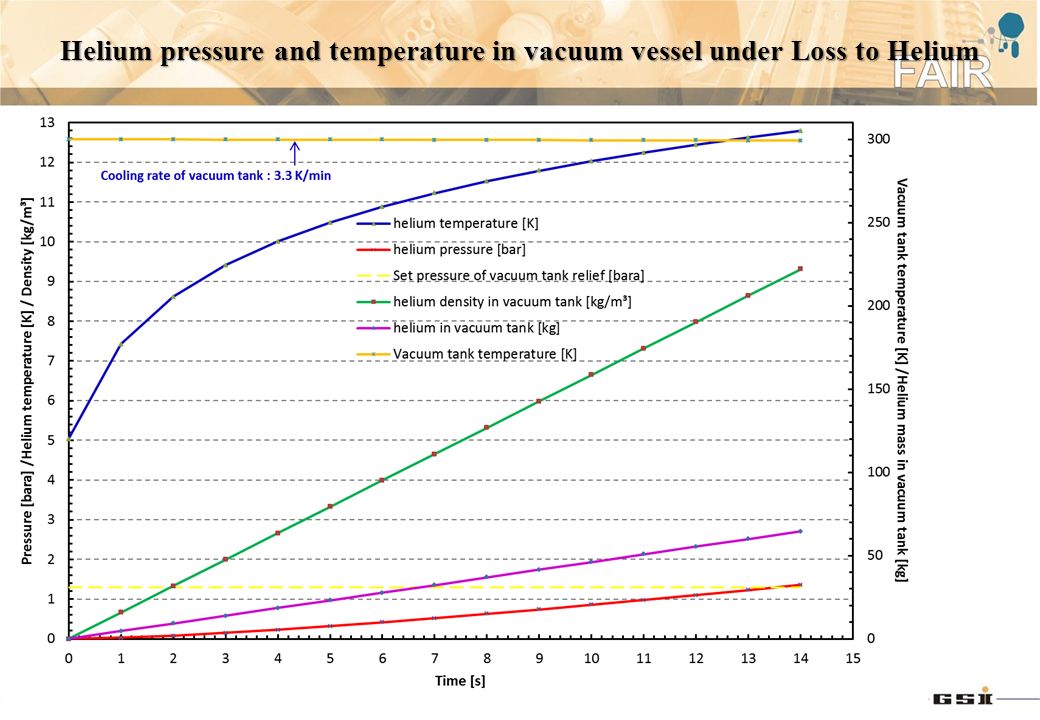
5
Helium pressure and temperature in vacuum vessel under Loss to Helium

7
Size of relief valve vs. venting temperature The minumum size of the vacuum tank relief for long multiplet is about 350 mm in diameter

8
Conservative assumption: choked flow occurs at relief device The size of the vacuum tank relief in the calculation is 350 mm in diameter

9
Choked flow vs. size of the hole C = 0.7 (assumed) For the flow rate of 4.6 kg/s at choked conditions, the size of the hole on the LHe vessel is around 40 to 50 mm in diameter
 For the flow rate of 4.6 kg/s at choked conditions, the size of the hole on the LHe vessel is around 40 to 50 mm in diameter.")
10
Maximum inner diameter, 80 mm (5000 mm²) Minimum inner diameter, 25 mm (510 mm² =0.34 mm²/litre x 1500 litres) The sizes for insulation vacuum relief seems too small according to EN 13458-2:2002 European Standards (DIN/BS EN 13458) The size of the Vacuum tank relief device we chosen is much larger than the European Standards (DIN/BS EN 13458) requires.
 Minimum inner diameter, 25 mm (510 mm² =0.34 mm²/litre x 1500 litres) The sizes for insulation vacuum relief seems too small according to EN :2002 European Standards (DIN/BS EN 13458) The size of the Vacuum tank relief device we chosen is much larger than the European Standards (DIN/BS EN 13458) requires.")
11
The size of the vacuum tank relief device is about 350 mm in diamter, which is much larger than the Euqropen Standards (DIN/BS EN 13458) requires. ~ 350 mm

Similar presentations


 is co-funded by the European Commission within the Framework Programme 7 Capacities Specific Programme,>")


 GSI, Darmstadt Yu Xiang Meeting for Super-FRS magnets test.>")

, GSI, Darmstadt Yu Xiang, Hans Mueller* * Primay Beam Magnet Technology.>")


