Download presentation
Presentation is loading. Please wait.

1
SURVEYING II (CE 6404) CONTROL SURVEYING UNIT I By Mr.R.GOPALAKRISHNAN, Asst.Professor in Civil Engineering, Sri Venkateswara College of Engineering.

2
Syllabus Horizontal and vertical control methods specifications – Triangulation – baseline instruments and accessories corrections – satelite stations – reduction to centre – Trignometric levelling – single and reciprocal observations – traversing – Gale’s Table

3
Classification of surveying
Plane Surveying Geotedic Surveying

4
Plane Surveying Definition:
The Plane surveying is the type of surveying in which , the curvature of the earth is not considered and it is considered as a plane surface. The area surveyed should be less than 250 Sq.KM.

5
Geodetic surveying Definition: The Geodetic surveying is the type of surveying in which , the curvature of the earth is considered. The object of the Geodetic surveying is to determine very precisely the relative or absolute positions on the earth’s surface of a widely separated points. For larger area of survey work ( more than 250 Sq.KM)
")
6
Cont’d The relative positions are determined in terms of length and azimuth of the line joining them. The absolute positions are determined in terms of latitude and longitude & elevation above mean sea level.

7
Cont’d Geodetic surveying is carried out by Triangulation
Precise levelling

8
System of Triangles

9
Cont’d

10
Cont’d

11
Classification of Triangulation system
First order Triangulation system Second order Triangulation system Third order Triangulation system

12
First order Triangulation system
Average triangle closure : 1 to 3 seconds Length of the base line: to 15 KM Length of the side of the triangles : 30 to 150 KM The degree of accuracy : 1 in 5,00,000 Check on the base : 1 in 25,000

13
Second order Triangulation system
Average triangle closure : 3 to 8 seconds Length of the base line: to 5 KM Length of the side of the triangles : 8 to 65 KM The degree of accuracy : 1 in 5,00,00 Check on the base : 1 in 10,000

14
Third order Triangulation system
Average triangle closure : 6 to 12 seconds Length of the base line: to 3 KM Length of the side of the triangles : 1.5 to 10 KM The degree of accuracy : 1 in 5,000 Check on the base : 1 in 5,000

15
Routine or Process of triangulation Survey
Reconnaissance Erection of signals and towers Measurement of base lines Measurement of horizontal angles Computation of latitude and longitude Computation of all the values

16
Reconnaissance survey
Examination of the place to be surveyed Selection of the suitable sites for base lines Selection of suitable positions for Triangulation stations Determination of intervisibility and height of stations

17
Selection of Triangulation stations
Intervisibility and height of stations and it depends on 1. The distance between the stations 2. The relative elevation of stations 3. The profile of the intervening ground

18
Distance between the station
If there is no obstruction due to intervening ground , the distance of the visible horizon from a station of known elevation above datum is given by h = D² / 2R ( 1-2m)
")
19
Cont’d h= height of the station above datum D= distance between the visible horizon R= Mean radius of the earth m=mean coefficient of refraction the value of m is taken as = 0.07 for sight over land = 0.08 over sea h=0.574 D² ( h in feet and D in miles for m=0.07) h= D² ( h in metres and D in km for m=0.07)
 h= D² ( h in metres and D in km for m=0.07)")
20
Relative Elevation of station

21
Cont’d If there is no obstruction due to intervening ground the below formula can be used. h = D² / 2R ( 1-2m) Where h₂ =required elevation of B above datum D1 =Distance from A to the point of tangency D2 =Distance from B to the point of tangency D =the known distance between A and B

22
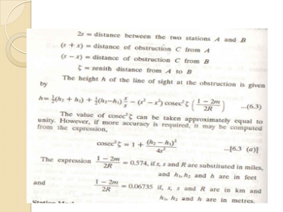
Profile of the intervening ground

24
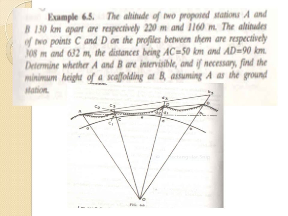
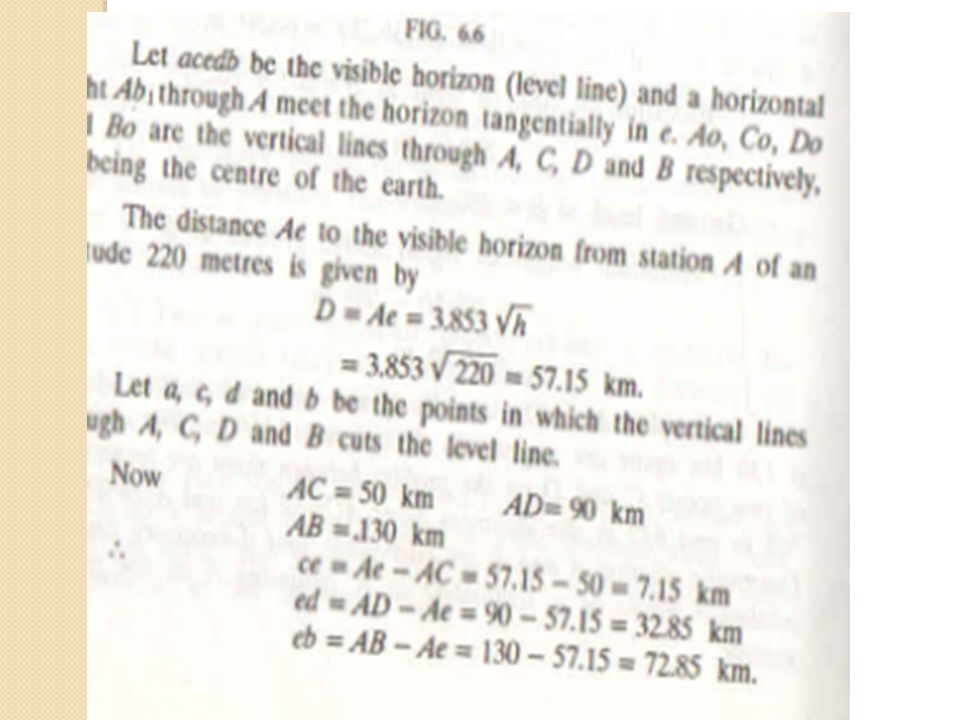
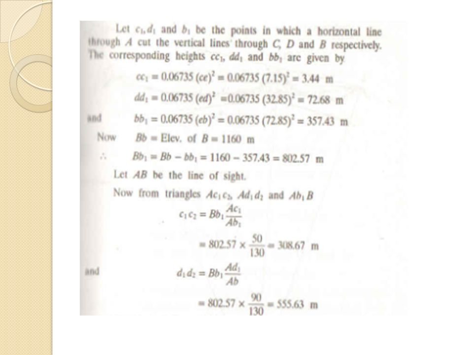
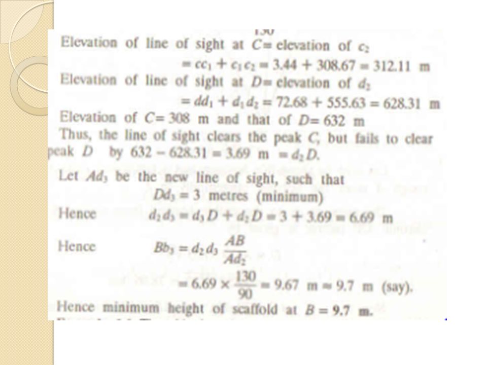
Problems Problem 1. The triangulation stations A and B 50KM apart, having elevations 243m and 260m respectively. The intervening ground may be assumed to have a uniform elevation, of 216m. Find the minimum height of the signal required at B, so that the line of sight may not pass the near the ground than 2.4m. Solution: Minimum elevation of the line of the sight = =218.4m

25
Cont’d Assuming as a datum level Elevation of A h₁ = = 24.6m The tangent distance D₁ corresponding to h₁ 24.6= h= D ₁ ² =19.12km D₂ = D- D₁ = =30.88km h₂ = D₂² = *30.88² = 64.18m The line of sight at B = = m Ground level at B = 260 m Minimum height of signal above the ground B is – 260 = say 23.0m

30
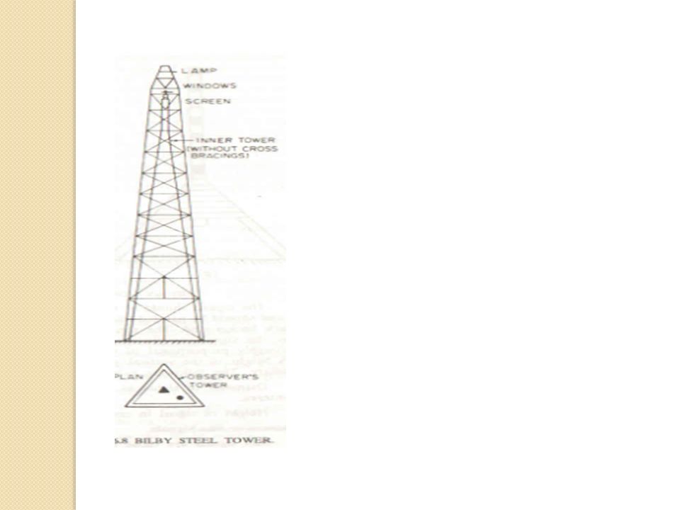
Towers A tower is a structure erected over a station for the support of the instrument and observing party and is provided when the station or signal or both to be elevated. It is made of masonry, timber, or steel. Small height – masonry tower Higher elevation – timber tower Easy handling – steel tower

32
Signals A signal is a device erected to define the exact position of an observed station. The signal may be classified as under below. Day light signal or non-luminous signal Sun or luminous signal Night signal

33
Non-Luminous signals

34
Non –luminous signals – Used for sights less than 30 Kilometres
Non –luminous signals – Used for sights less than 30 Kilometres. Under 6 km. Pole signals consisting of round pole painted black and white in alternate sections and supported on a tripod. Diameter signal varies from 1.3D to 1.9D, where D is in KM. Height of signal in cm= 13.3D,where D is in KM

35
Luminous or Sun signals: Used when the line of sight exceeds 30km Sun signals: Exceeds 30km Night signals: Various forms of oil lamp with reflectors less than 80km Acetylene lamp – Upto 80km

36
Phase of Signals Phase of signal is the error of bisection, which arises from the fact, under illumination the signal is partly in light and partly in shade. The observer sees the illuminated portion and bisects it. Thus the apparent displacements of signal.

37
Phase correction for the signals
Phase correction is necessary for the following conditions. When the observation is made on the bright portion When the observation is made on the bright line

38
Phase correction in the Bright portion

39
Bright portion is FD A= Position of the observer B= Centre of the signal FD= visible portion of the illuminated surface AE= line of sight E=midpoint of FD β = phase correction Φ1 and Φ2=Angles which the extreme ends of the visible portion make with AB α = The angle which direction of the sun makes with AB r = radius of the signal D= Distance AB β =r cos²α/2) / Dsin 1” seconds or * (r cos²α/2 )/D
 / Dsin 1 seconds or * (r cos²α/2 )/D")
40
Phase correction in the Bright line

41
Cont’d β =r cosα/2) / Dsin 1” seconds or * (r cosα/2 )/D Seconds
 / Dsin 1 seconds or * (r cosα/2 )/D Seconds")
42
Baseline Measurement Selection of site for Baseline Base net
Base measurement apparatus Rigid bars, Tapes ( steel tapes), Invar tapes
, Invar tapes.")
43
Equipments for baseline measurement
Three standard tapes Straining device Spring balance or pulley Six thermometers Marking stakes Supporting stakes Steel tapes for setting out tripods

44
Model – colby apparatus

45
Corrections to length of the baseline- Tape corrections
Correction for absolute length Correction for temperature Correction for pull or tension Correction for sag Correction for slope Correction for alignment Reduction to sealevel

46
Measurement of horizontal angles Repetition method Direction method

47
Cont’d Direction method Ist order -16 sets 2nd order – 4 sets 3rd order – 2 sets

48
Satellite Station & Reduction to centre
In order to better visibility, objects such as church spires, flagpoles sometimes selected as the Triangulation stations. The observations are taken from such a station, it is impossible to set up an instrument over it. In such a case a satellite station or false station is selected as near to the main station. The observations are taken to other triangulation stations with the same precision as in the case of True stations. The operation of applying the corrections due to the eccentricity is generally known as Reduction Centre.

49
Cont’d The distance between the True station and the Satellite station is determined either by Trignometrical levelling or triangulation. These stations should be avoided as far as possible in Primary Triangulation.

50
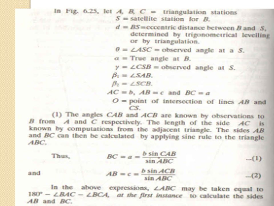
Cont’d (Fig 1)
")
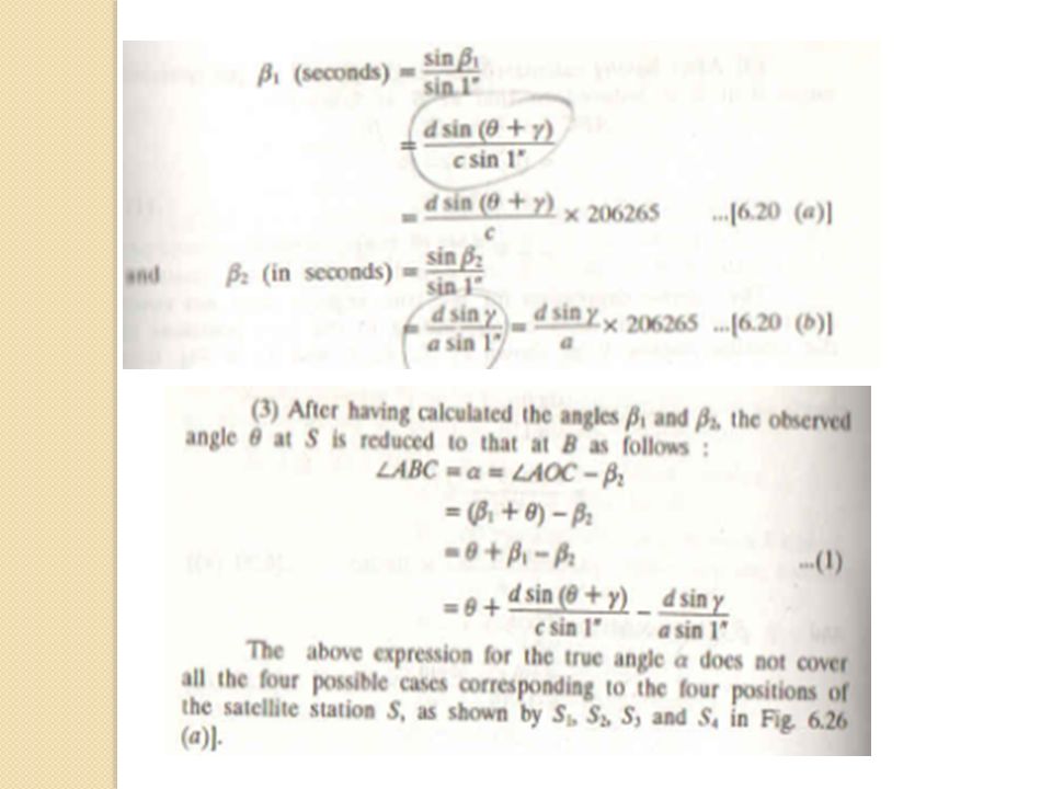
54
Cont’d The above expressions for the true angle α does not cover all the four possible cases There are four different positions of satellite station. Case I: Referring Fig 1 The true angle α = Ө + β₁ - β₂

55
Cont’d Case II: The position of S right of B
The true angle α = Angle AOC - β₁ α = = (Ө + β₂) - β₁
 - β₁.")
56
Cont’d Case III: The position of S between AC and B The true angle
α = Ө - β₂ - β₁

57
Cont’d Case IV: The position of S is at the end The true angle
α = Ө - β₂ - β₁

58
Sign of Corrections When number of angles are observed from the Satellite S it is convenient to assume SB as an Arbitrary meridian., Observations are reduced to this meridian corrections are computed from below formula. β in seconds = d sin Ө / D sin 1″ it is convenient

59
Cont’d Ө = observed angle reduced to assumed meridian. D = distance from the True station to assumed meridian. β ( the sign will be same as that of sin Ө)
")
60
Eccentricity of signals
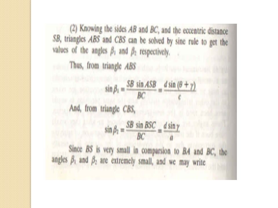
Observations are made upon a signal which is out of centre, it is essential to correct the angles. β₁ = d sin (Ө + γ) / c sin1” β2 = d sin γ / a sin1”
 / c sin1 β2 = d sin γ / a sin1")
61
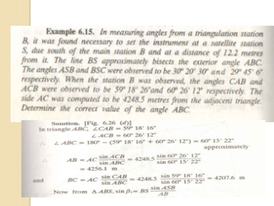
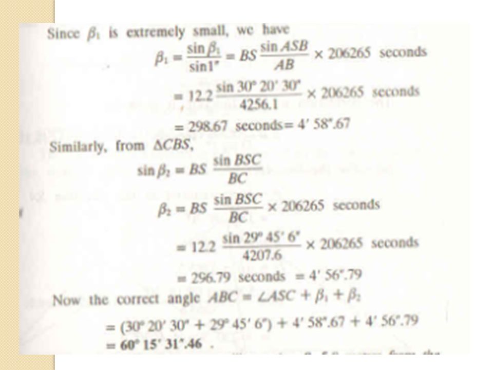
Problems on satelite station
From an eccentric station S, 12.25m to the west of the main station B, the following angles were measured. Angle BSC =76° 25’ 32”, angle CSA = 54° 32’ 20”, the stations S and C are to the opposite sides of the line AB. Calculate the correct angle ABC if the lengths AB and AC are and metres respectively. Soln: Referring Fig 1 AB = c = m BC = a = m BS = d = m

62
Cont’d

65
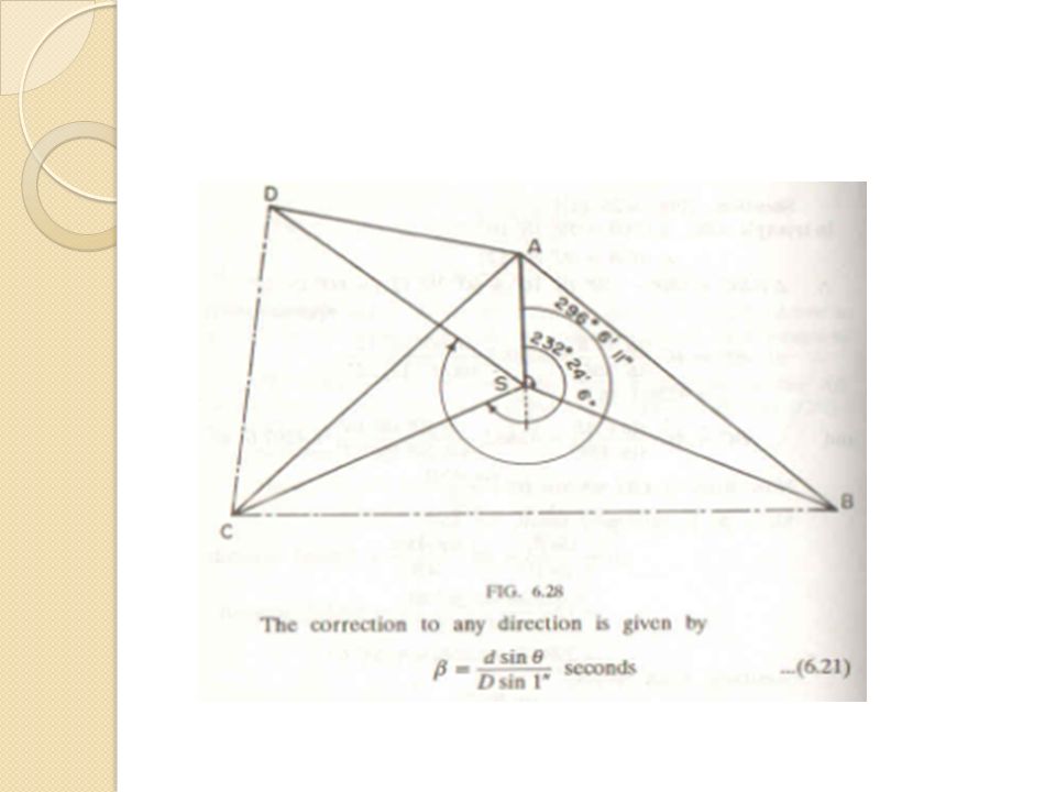
Prob. 3. From a satellite station S, 5
Prob.3. From a satellite station S, 5.8m from the main triangulation station A, the following directions were observed. Length AB = , AC = AD = m determine the directions of AB and AC, AD. A 0° 0’ 0” B 132° 18’ 30” C 232° 24’ 6” D 296° 6’ 11”

67
For line AB: Ө = Angle reduced to the direction of SA = 132° 18’ 30” d = AS = 5.8m , D = AB = m β = (d sin Ө / D sin 1” ) * seconds = 270.9” = 4° 30.9” ( Direction of AB = Direction of SB + β = 132° 23’ 0.9” For line AC: Direction of AC = 232° 20’ 4.3” For line AD : Direction of AD = 296° 0’ 22.9”
 * seconds = = 4° 30.9 ( Direction of AB = Direction of SB + β = 132° 23’ 0.9 For line AC: Direction of AC = 232° 20’ 4.3 For line AD : Direction of AD = 296° 0’ 22.9")
68
Trignometrical Levelling
Trignometrical levelling is the process of determining the differences of elevations of stations from observed vertical angles and known distances, which are assumed to be either horizontal or geodetic lengths at mean sea level. The vertical angles may be measured by using theodolite and horizontal distances may be measured by tape or chain.

69
Cont’d Trignometrical levelling can be classified as
Observations for height and distances Geodetical observations Heights and distances : 1. Base of the object accessible 2. Base of the object inaccessible (Instrument stations in the same vertical plane) 3. Base of the object inaccessible (Instrument stations not in the same vertical plane)
 3. Base of the object inaccessible (Instrument stations not in the same vertical plane)")
70
Base of the object accessible RL of Q = RL of P + s + Dtanα (applied when D is small)
")
71
Base of the object accessible – D is large – Combined of correction of curvature and refraction considered

72
Cont’d PQ’ = QP” = D Angle QQ’P = 90 ̊ QQ’ = Dtanα The true difference in elevation between P and Q is QQ” Combined correction for curvature and refraction = Q’Q” added to QQ’ and will get the true difference in elevation QQ” C = D² RL of Q = RL of BM + S + Dtanα + C ( Use + for elevation, - for depression)
")
73
Base of the object Inaccessible (Instrument station in the same vertical plane- Axis at the same level)
")
74
Cont’d Let h = QQ’ α1 = Angle of elevation from A at Q α2 = Angle of elevation from B at Q B = horizontal distance between the instrument station D = horizontal distance between P and Q ∆ AQQ’ = h = D tanα1 ∆ BQQ’ = h = ( b+D) tanα2 D tanα1 = ( b+D) tanα2 D = btanα2 / (tanα1 – tanα2) h= D tanα1 h= b tan α1 tanα2 / (tanα1 – tanα2)
 tanα2 D tanα1 = ( b+D) tanα2 D = btanα2 / (tanα1 – tanα2) h= D tanα1 h= b tan α1 tanα2 / (tanα1 – tanα2)")
75
Cont’d (Instrument axis at different levels)
")
76
Cont’d

77
Instrument axis at different levels – Cont’d

78
Cont’d

79
Instrument axis at very different levels

80
Cont’d

81
Cont’d D = btanα2 – S/ (tanα1 – tanα2) h1 = Dtanα1 = (btanα2 – S) tanα1/ (tanα1 – tanα2) Height of the station P above the axis at B= h – r = btanα – r Height of the station A above the axis at B= S= = btanα – r + h’ Substitute S = (b + D)tanα2 – Dtanα1 RL of Q = RL of A + h1 RL of Q = RL of B + S + h1
 h1 = Dtanα1 = (btanα2 – S) tanα1/ (tanα1 – tanα2) Height of the station P above the axis at B= h – r = btanα – r Height of the station A above the axis at B= S= = btanα – r + h’ Substitute S = (b + D)tanα2 – Dtanα1 RL of Q = RL of A + h1 RL of Q = RL of B + S + h1")
82
TERRESTRIAL REFRACTION

83
Cont’d Correction for refraction (r) towards the point of elevation = α1 – r Correction for refraction (r) towards the point of depression = β1 + r (Correction for refraction is subtractive and additive tothe angle of depression) Co-efficient of refraction (m): It is the ratio of angle of Refraction and the angle subtended at the centre of the earth by the distance over which observation are taken. m = r / Φ ( Values varies from 0.06 to 0.08)
 towards the point of elevation = α1 – r Correction for refraction (r) towards the point of depression = β1 + r (Correction for refraction is subtractive and additive tothe angle of depression) Co-efficient of refraction (m): It is the ratio of angle of Refraction and the angle subtended at the centre of the earth by the distance over which observation are taken. m = r / Φ ( Values varies from 0.06 to 0.08)")
84
Cont’d Determination of correction for refraction (r) – Distance d small and H large r =( Φ/ 2) – (β1 – α1)/2 Substituing r = m Φ Β1 = α1 + Φ(1-2m), thus the observed angles of depression exceeds the angle of elevation by the amount of Φ(1-2m) Determination of correction for refraction (r) – Distance d large and H small r =( Φ/ 2) – (β1 + α1)/2 which reduces to (β1 + α1) = Φ(1-2m) Correction for curvature: Correction for curvature is Ө/2 for angle of elevation and –Ө / 2 for angle of depression Combined correction: Angular correction of refraction = mӨ = md/ R sin 1” Seconds Hence, combined angular correction = { d/ 2Rsin 1” – md/ Rsin 1”} = (1-2m)d/ 2Rsin 1” The combined correction is positive for angles of elevation and negative for angles of depression. .
, thus the observed angles of depression exceeds the angle of elevation by the amount of Φ(1-2m) Determination of correction for refraction (r) – Distance d large and H small. r =( Φ/ 2) – (β1 + α1)/2 which reduces to. (β1 + α1) = Φ(1-2m) Correction for curvature: Correction for curvature is Ө/2 for angle of elevation and –Ө / 2 for angle of depression. Combined correction: Angular correction of refraction = mӨ = md/ R sin 1 Seconds. Hence, combined angular correction = { d/ 2Rsin 1 – md/ Rsin 1 } = (1-2m)d/ 2Rsin 1 The combined correction is positive for angles of elevation and negative for angles of depression. .")
Similar presentations

 Contents 11.1 Area of Triangles 11.2 Sine Formula>")


 = the length of the path travelled by light in vacuum during a specific fraction of a second (1/299 792.>")


 Florben G. Mendoza.>")
 2.Swapnil A Parmar (140370119204) 3.Pratik C Patel (140370119251) B.E- 2 SEM MECHANICAL ENGINEERING LINEAR MEASUREMENTS.>")
