Download presentation
Presentation is loading. Please wait.

1
Manufacturing Process II
Reverse Engineering Manufacturing Process II

2
What is Reverse Engineering?
"Reverse Engineering is the process of taking a finished product and reconstructing design data in a format from which new parts or molds can be produced." -The Society of Manufacturing Engineers (SME) Reverse Engineering (RE) is also defined by the Military Handbook MIL-HDBK-115 (ME) as "…the process of duplicating an item functionally and dimensionally by physically examining and measuring existing parts to develop the technical data (physical and material characteristics) required for competitive procurement."
 Reverse Engineering (RE) is also defined by the Military Handbook MIL-HDBK-115 (ME) as …the process of duplicating an item functionally and dimensionally by physically examining and measuring existing parts to develop the technical data (physical and material characteristics) required for competitive procurement.")
3
Common Applications The most common applications for reverse engineering are: Original equipment manufacturer (OEM) unable or unwilling to provide replacement parts Prototypes with no models/drawings Worn or broken components for which there is no source of supply For base model geometry to edit and tailor for improved functionality or new application
 unable or unwilling to provide replacement parts. Prototypes with no models/drawings. Worn or broken components for which there is no source of supply. For base model geometry to edit and tailor for improved functionality or new application.")
4
Importance Medical application of reverse engineering is very necessary for the following reasons: The digital model does not exist The shapes of medical objects are very complex.

5
Reverse Engineering Process
Obtain Dimensional Data Analyze Data Creation of the CAD Model/Drawing Ensuring Quality Make the part

6
Alternative Approach Point Cloud to NURBS- Non-Uniform Rational B-Splines The process here is a little more straightforward than with CMM based reverse engineering. Using 3-D scanner the object is scanned with full 3D coverage. Separate partial scans are aligned and merged into a single surface made of thousands or millions of triangles in a large mesh. In some cases, parts of the surface are obscured from the scanner and must be filled in manually. Other work is done to enhance features such as sharp edges that may be softened in the scan process. Once the polygon surface is watertight and cleaned up a NURBS surface is generated. NURBS surfaces can be modified in limited fashion by 3-D CAD packages or can be exported directly to IGES or other formats for machining or molding. NURBS, Non-Uniform Rational B-Splines, are mathematical representations of 3-D geometry that can accurately describe any shape from a simple 2-D line, circle, arc, or curve to the most complex 3-D organic free-form surface or solid. Because of their flexibility and accuracy, NURBS models can be used in any process from illustration and animation to manufacturing.

7
Alternative Approach (Cont.)
")
8
Reverse engineering example 1
Point cloud data Surface triangles Construct Boundaries Patch: 1004, Triangle: Construct Grids SolidWorks Model Decimate Grids NURBS surface fitting

9
Reverse engineering example 2
Testjaw STL in GeoMagic Boundary Grid IGES input to Solid Work Fit surface (NURBS) and IGES out
 and IGES out.")
10
Surface Reconstruction and refinement
CAD Based model generation 3-D Scanned DATA 3D Reconstruction Point Cloud Data file NURBS surfaces IGES file conversion CAD model Surface Reconstruction and refinement

11
3-D Scanner Usage Example 1
3D scanner was used to create 3D models to generate movie teaser scan clay sculptures and plaster head casts of actors. Then utilize this raw data to extract a more precise and lighter mesh (details on following pages). These lighter meshes are more appropriate for animating.
. These lighter meshes are more appropriate for animating.")
12
3-D Scanner Usage Example 1 (movie teaser)
Add alignment dots to help the alignment process of the separate scans Created a paper template that lies under scanner and the platen Polish the scans Use other software to edit the 3-D model to create the movie teaser

13
3-D Scanner Usage Example 2 (Remote controller)
Solid view (front) Texture view (front) Mesh close up Solid view (back)
 Texture view (front) Mesh close up. Solid view (back)")
14
3-D Scanner Usage Example 3 (Tape Measure)
Photo of tape measure Scan-texture view of front Scan-solid view of front Close up of back Close up of back-Mesh view Mesh detail

15
3D scanning & 3D printing

16
3D Scanning 3D scanning becoming widely used, both in traditional areas like model building for movies and in new areas such as art history and archeology.

17
Stereo Triangulation I J Correspondence is hard!
Here we see five frames from water flow sequence. Standard stereo method considers one pair of images. For each pixel in one image, we look for corresponding pixel in the other image. Then we intersect the line of sight to reconstruct the 3D surface. The key problem is computing correspondence. A simple way to do it is for each in the left image, we look for pixels on the same row in the right image and choose the pixel with most similar color. This can be done by minimizing the following error function. Correspondence is hard!

18
Structured Light Triangulation
J Correspondence becomes easier!

19
Triangulation Project laser stripe onto object Light Plane Object
Camera The first stage in the real-time pipeline is the range scanner. It’s based on the idea of triangulation. In the simplest case, this consists of projecting a stripe of light onto a scene, looking at it from an angle… Project laser stripe onto object

20
Triangulation Depth from ray-plane triangulation: Object
Light Plane Object Laser Camera Image Point … and triangulating between a plane from the point of view of the light source and a ray from the point of view of the camera. In the simplest case of a laser triangulation scanner, this yields data from a single contour on the object at a time, and you can sweep the line across the surface to stack up a bunch of these contours and get a scan of an entire patch of surface. Depth from ray-plane triangulation: Intersect camera ray with light plane

21
Example: Laser scanner
Cyberware® face and head scanner + very accurate < 0.01 mm − more than 10sec per scan

22
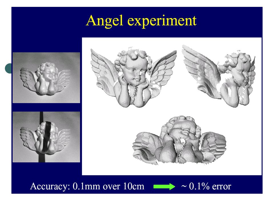
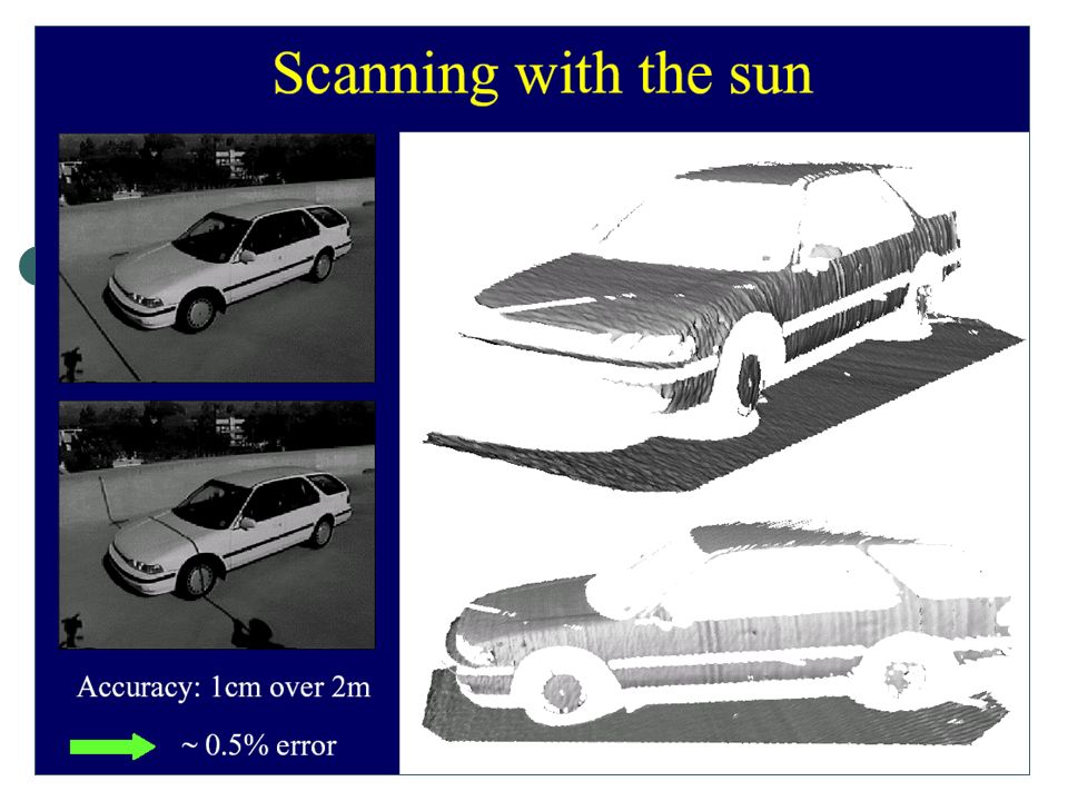
Example: Laser scanner
Digital Michelangelo Project

25
3D Model Acquisition Pipeline
3D Scanner To understand the problem, let’s look at the entire 3D model acquisition pipeline. We start with the 3D scanner, which typically returns a range image: 3D shape as seen from a single point of view.

26
3D Model Acquisition Pipeline
3D Scanner View Planning In order to get the entire object, need to move scanner around object (or move object w.r.t. scanner). This requires figuring out where to put the scanner.
. This requires figuring out where to put the scanner.")
27
3D Model Acquisition Pipeline
3D Scanner View Planning Alignment Multiple scans need to be aligned.

28
3D Model Acquisition Pipeline
3D Scanner View Planning Alignment Merging The scans are then merged into a single model.

29
3D Model Acquisition Pipeline
3D Scanner View Planning Alignment Done? Merging Now, the user needs to plan further scans and determine whether the entire object has been covered.

30
3D Model Acquisition Pipeline
3D Scanner View Planning Alignment Done? Merging To do this, user needs some sort of feedback, so the final piece of the pipeline is some sort of rendering. Display

31
How to do the reverse engr.?
1.Case studies of scanning and reverse engineering 2. The equipment will be used in your lab 3. Examples and demo

32
Reverse Engineering Project (Team of 5 members needing 2 hous)
Use NextEngine 3D Laser scanning system in Hess Lab to do: Learn how to get started: tutorial Scan the parts: We will assign a part for each group. Before scanning, you need to mark the reference points. Data analysis: View the data you just capture and polish them. Align the data and put them together, then trim and blend your scan data. You can save your scans as STL files in order to view in other 3-D program ( Solidwork, Maya, Geomagic, Rhinoceros) and do some necessary changes. Import your file to RP (Rapid prototype) machine (Z-Corporation) to make the part. Hand in a project report and RP part by Week 5.
 and do some necessary changes. Import your file to RP (Rapid prototype) machine (Z-Corporation) to make the part. Hand in a project report and RP part by Week 5.")
33
Home Work What is RE in your words, and what is its pros and cons and applications? Find 1-2 papers to introduce RE and its applications.

Similar presentations


>")


 Introduction to CAD>")


