Download presentation
Presentation is loading. Please wait.

1
EEK260 -Electrical Machines
By Dr. Mohamad Kamarol Mohd Jamil Room: 2.32 Ext: 6064

2
Practical Transformers
What is practical transformer? The winding of practical transformer have resistance (Wildi, pg 197) The cores are not infinitely permeable (Wildi, pg 197) The flux produced by the primary is not completely captured by the secondary. (Wildi, pg 197) Produced leakage flux, eddy-current and hysteresis losses, which contribute to the temperature rise. (Wildi, pg 197)
 The cores are not infinitely permeable (Wildi, pg 197) The flux produced by the primary is not completely captured by the secondary. (Wildi, pg 197) Produced leakage flux, eddy-current and hysteresis losses, which contribute to the temperature rise. (Wildi, pg 197)")
3
Practical transformer
Over/Eddy- current loss, hysteresis loss and iron loss Copper loss at coil resistance Magnetic flux Magnetic flux leakage Fig. 1 Practical transformer

4
Exciting/magnetization current in practical transformer
When an AC power source is connected to a transformer, the current flows in the coils to establish a sinusoidal flux in the real ferromagnetic core. This current is called exciting current, iΦ. No hysteresis With hysteresis

5
No hysteresis Let consider a B-H characteristic with no hysteresis.
It can be rescaled to Φ-i curve for the core as shown below The exciting current is purely lagging current The exciting winding can be represented by a pure inductance iΦ lag the voltage e by 90° No power loss is involved

6
With hysteresis Magnetization of core Core loss
The exciting current is nonsinusoidal as well as nonsymmetrical with respect to the voltage waveform The exciting current can be split into two components, 1.Core-loss current ic which is in phase with voltage e – modeled by a resistance Rc 2. Magnetization current im which is in phase with Φ and symmetrical with respect to e and lagging by 90°- modeled by reactance Lm or Xm

7
An imperfect core of practical transformer
Pm: iron losses (W) Qm: reactive power needed to set up the mutual flux Φm (Var)
 Qm: reactive power needed to set up the mutual flux Φm (Var)")
8
Example 1(10-1) A large transformer operating at no-load draws an exciting current I0 of 5 A when the primary is connected to a 120 V, 60 Hz source (Fig. 2). From a wattmeter test it is known that the iron losses are equal to 180 W. Calculate, The reactive power absorbed by the core The value of Rm and Xm The value of If, Im and I0 Fig. 2
. From a wattmeter test it is known that the iron losses are equal to 180 W. Calculate, The reactive power absorbed by the core. The value of Rm and Xm. The value of If, Im and I0. Fig. 2.")
9
Solution for example 1(10-1)
a) The apparent power supplied to the core is The iron losses are The reactive power absorbed by the core is b) The impedance corresponding to the iron losses is
 The apparent power supplied to the core is. The iron losses are. The reactive power absorbed by the core is. b) The impedance corresponding to the iron losses is.")
10
Solution for example 1(10-1)
The magnetizing reactance is c) The current needed to supply the iron losses is If =1.5 A 120 V The magnetizing current is Im =4.8 A I0=5 A The exciting current is Φm
 The current needed to supply the iron losses is. If =1.5 A. 120 V. The magnetizing current is. Im =4.8 A. I0=5 A. The exciting current is. Φm.")
11
The equivalent circuit of a transformer
The losses that occur in real transformers have to be accounted for any accurate model of transformer behavior. The major items to be considered in construction of such model are 1. Copper losses (I2R). - Are the resistive heating losses in the primary and secondary windings of the transformer. Proportional to the square of the current in the windings. 2. Eddy current losses. - Are the resistive heating losses in the core of the transformer. Proportional to the square of the voltage applied to transformer
. - Are the resistive heating losses in the primary and secondary windings of the transformer. Proportional to the square of the current in the windings. 2. Eddy current losses. - Are the resistive heating losses in the core of the transformer. Proportional to the square of the voltage applied to transformer.")
12
The equivalent circuit of a transformer
3. Hysteresis losses. - Are associated with the rearrangement of the magnetic domains in the core during each cycle. 4. Leakage flux . - The fluxes which escape the core and pass through only one of the transformer windings. It produce a self-inductance in the primary and secondary coils, and the effects of this inductance must be accounted for.

13
The equivalent circuit of a practical transformer
Leakage flux Leakage flux Copper losses Copper losses Ideal transformer Core excitation effects

14
Example 2 (10-2) The secondary winding of a transformer possesses 180 turns. When the transformer is under load, the secondary current has an effective value of 18 A, 60 Hz. Furthermore, the mutual Φm has a peak value of 20mWb. The secondary leakage flux Φf2 has a peak value of 3mWb. Calculate The voltage induced in the secondary winding by its leakage flux The value of the secondary leakage reactance The value of E2 induced by the mutual flux Φm = V = 8 Ω = 959 V

15
Simplifying the equivalent circuit
Fig.3 Complete equivalent circuit of a transformer at no load Simplify to I2=0, I1=0 Only I0 flows in R1 and Xf1. However these impedances are so small that the voltage drop across them is negligible

16
Simplifying the equivalent circuit
Fig.4 Complete equivalent circuit of a transformer at full-load Simplify to Ip >20I0 Only I0 can be neglected. However these impedances are so small that the voltage drop across them is negligible

17
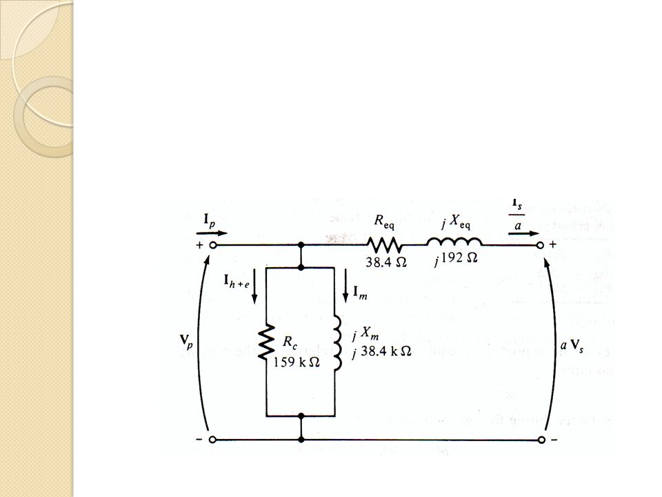
Simplifying the equivalent circuit
Simplify the circuit by shifting everything to the primary side

18
Simplifying the equivalent circuit
Produces an internal voltage drop when the transformer is loaded. It affects the voltage regulation of the transformer Transformer above 500 kVA possess a leakage reactance XP that is at least 5 times greater than RP In such transformer RP can be neglected as far as voltage and currents are concerned

19
Determination of equivalent circuit parameters
R1, R2, Xf1, Xf2, Rm, Xm These parameters can be directly and more easily determined by performing tests that involve little power consumption. No-load test or open-circuit test 2. Short-circuit test

20
No-load test (or Open-circuit test)
This test is performed by applying a voltage to either the high-voltage side or low voltage side, whichever is convenient. Possible to determine the excitation branch the magnitude & the angle of excitation impedance the power factor of the input current

21
No-load test (or Open-circuit test)
The test result give the following information: Pm = active power absorbed by core EP I0 = Sm = apparent power absorbed by core Qm = reactive power absorbed by core Resistance Rm corresponding to the core loss is Magnetizing reactance Xm is

22
No-load test (or Open-circuit test)
The easiest way to calculate the values of Rm and Xm is to look first at the admittance of the excitation branch Therefore the total excitation admittance is

23
No-load test (or Open-circuit test)
The magnitude of the excitation admittance can be found from the open circuit test voltage and current The angle of the admittance can be found from the knowledge of the circuit power factor Where the PF is always lagging for a real transformer

24
Short-circuit test Secondary winding is short-circuited and the primary terminals are connected to a fairly low-voltage source. (lower than normal, less than 5% of rated voltage) ISC < its nominal value To prevent Overheating Rapid change in winding resistance RP XP ESC ISC
 ISC < its nominal value. To prevent. Overheating. Rapid change in winding resistance. RP. XP. ESC. ISC.")
25
Short-circuit test The input voltage is so low during the short-circuit test, thus the current flows (I0) through the excitation branch can be negligible RP XP ESC ISC If the excitation current is ignored, then all the voltage drop in the transformer can be attributed to the series elements in the circuit The magnitude of the series impedances referred to the primary side of the transformer
 through the excitation branch can be negligible. RP. XP. ESC. ISC. If the excitation current is ignored, then all the voltage drop in the transformer can be attributed to the series elements in the circuit. The magnitude of the series impedances referred to the primary side of the transformer.")
26
Short-circuit test Total transformer impedance referred to the primary side is The PF of the current given by And is lagging. Therefore the total impedance is Total transformer resistance and leakage reactance referred to the primary side

27
Transformer rating The losses appear in the form of heat yield to
1) Increase in temperature 2) Drop the efficiency To keep the transformer level at an acceptable level, both of the applied voltage and current drawn by the load must be limited. This two limits determine the nominal voltage Enp and nominal current Inp Temperature rise of a transformer is directly related to the apparent power that flows through it
 Increase in temperature. 2) Drop the efficiency. To keep the transformer level at an acceptable level, both of the applied voltage and current drawn by the load must be limited. This two limits determine the nominal voltage Enp and nominal current Inp. Temperature rise of a transformer is directly related to the apparent power that flows through it.")
28
Transformer rating So what are the meanings of these rating?
The voltage ratings indicate that the transformer has two windings, Rated for 1100 V Rated for 110 V These voltages are proportional to their respective number of turns, therefore the turns ratio also represent the voltage ratio. For example, 10 kVA rating means that each winding is designed for 10 kVA. Therefore, the current rating for HV and LV winding is

29
Actual transformer values
Rated power Rated voltage Rated current Theodore Wildi, “Electrical machines, drives and power systems”, pg 202

30
Voltage regulation Since a real transformer has series impedance within it, the output voltage of a transformer varies with the load even if the input voltage remains constant. To conveniently compare transformers in this respect, it is usual to define a quantity called voltage regulation Voltage regulation is a quantity that compares the output voltage of the transformer at no load with the output voltage at full load Secondary voltage at no-load Secondary voltage at full-load Usually it is a good practice to have as small a voltage regulation as possible.

31
Voltage regulation The voltage regulation can be expressed as
How can the voltage regulation of a transformer be determined? To determine the VR of a transformer, it is necessary to understand the voltage drops within it. ES ES Approximate transformer model referred to secondary side

32
Voltage regulation VR of a transformer depends both on the magnitude of this series impedance and on phase angle of the current flowing through the transformer The easiest way to determine the effect of the impedances and the current phase angles on the transformer VR is to examine a phasor diagram ES VR > 0 A phasor diagram of a transformer operating at a lagging power factor.

33
Voltage Regulation PF = unity VR > 0 PF = leading VR < 0

34
Simplified VR calculation

35
Transformer Efficiency
The efficiency of a transformer at a given load, can be calculated as follows Where, Since the output power is given as The efficiency can be expressed as

36
Example 3 (10-4) The nameplate of a distribution transformer indicates 250 kVA, 60 Hz, primary 4160 V, secondary 480 V. Calculate the nominal primary and secondary currents If we apply 2000 V to the 4160 V primary, can we still draw 250 kVA from the transformer

37
Example 4 (10-5) A single-phase transformer rated at 3000 kVA, 69 kV/4.16 kV, 60 Hz has a total internal impedance Zp of 127 Ω, referred to the primary side. Calculate The rated primary and secondary currents The voltage regulation from no-load to full-load for a 2000kW resistive load, knowing that the primary supply voltage is fixed at 69 kV The primary and secondary currents if the secondary is accidentally short-circuited

38
Solution for example 4 a. Rated primary current
Rated secondary current b. Leakage reactance, where resistance can be ignored due to the rated voltage exceeds 500kVA Determine the load Z

39
Solution for example 4 Load impedance referred to primary side
c. If the secondary is accidentally short-circuited, Voltage at full-load

40
Example 5(10-6) During a short-circuit test on a transformer rated 500 kVA, 69 KV/4.16 kV, 60 Hz, the following voltage, current and power measurements were made. Terminal X1, X2 were in short-circuit as shown in figure below. The measurement results are as follows ESC = 2600 V ISC = 4 A PSC = 2400 W Calculate the value of the reactance and resistance of the transformer referred to the HV side

41
Solution for Example 5 Transformer impedance referred to the primary side is Resistance referred to the primary is Leakage reactance referred to the primary is

42
Example 6 (10-7) An open-circuit test was conducted on the transformer given in example 3. The following results were obtained when the lo-voltage winding was excited. (in some cases, such as in a repair shop, a 69 kV voltage may not be available and the open-circuit test has to be done by exciting the LV winding at its rated voltage) ES = 4160 V, I0 = 2 A, Pm = 5000 W Using this information and the transformer characteristics found in example 3, calculate: The values of Xm and Rm on the primary side The efficiency of the transformer when it supplies a load of 250 kVA, whose p.f is 80% lagging.
 ES = 4160 V, I0 = 2 A, Pm = 5000 W. Using this information and the transformer characteristics found in example 3, calculate: The values of Xm and Rm on the primary side. The efficiency of the transformer when it supplies a load of 250 kVA, whose p.f is 80% lagging.")
43
Solution of example 6(a)
Referred to secondary side The values of excitation impedance referred to the primary side will be a2 times greater

44
Solution of example 6(b)
S = 250 kVA The load current is The turns ratio is The total losses are The current on the primary side is The active power delivered by the transformer to the load The total copper loss (primary and secondary) is The active power received by the transformer is The efficiency
 is. The active power received by the transformer is. The efficiency.")
45
The per-unit system of measurement
Per-unit system is another approach to solving circuit containing transformer which eliminate the need of explicit voltage level conversion. The circuit containing many transformer can be solved easily with less chance of error. Instead of dealing with ohm, amperes, volts and kilowatts, each electrical quantity is measured in a decimal fraction

46
Per-unit system To define a given per unit system, the voltage and power (or apparent power) should be selected Once the base values of S (or P) and V have been selected, all other base values can be computed easily
 and V have been selected, all other base values can be computed easily.")
47
Example 7 A simple power system contains a 480 V generator connected to an ideal 1:10 step-up transformer, a transmission line, an ideal 20:1 step-down transformer, and a load. The impedance of the transmission line is 20+j60 Ω, and the impedance of the load is ° Ω. The base value for this system are chosen to be 480 V and 10 kVA at the generator. Find the base voltage, current, impedance and apparent power at every point in the power system Convert this system to its per-unit equivalent circuit Find the power supplied to the load in this system Find the power lost in the transmission line

48
Solution for example 7(a)
a. In the region 1,

49
Solution for example 7(a)
Turns ratio of first transformer (T1) is a=1/10 Therefore the voltage in the region 2 (transmission line region) is
 is a=1/10. Therefore the voltage in the region 2 (transmission line region) is.")
50
Solution for example 7(a)
Turns ratio of first transformer (T2) is a=20/1 Therefore the voltage in the region 3 (load region) is
 is a=20/1. Therefore the voltage in the region 3 (load region) is.")
51
Solution for example 7(b)
To convert a power to a per-unit system, each component must be divided by its base value in its region of the system The generator region (region 1) The line impedance in transmission region is The load impedance in load region
 The line impedance in transmission region is. The load impedance in load region.")
52
Solution for example 7(c)
Power of the load Actual power to the load

53
Solution for example 7(d)
Per-unit power lost in transmission line is Actual power lost in transmission line is

54
Exercise 1 The equivalent circuit impedances of a 20 kVA, 8000/240 V, 60 Hz transformer are to be determined. The open circuit test and short circuit test were performed on the primary side of the transformer and following data were taken Open circuit test (on primary) Short circuit test (on primary) Voc= 8000 V Vsc = 489 V Ioc= A Isc= 2.5 A Poc = 400 W Psc = 240 W Find the impedance of the approximate equivalent circuit referred to the primary side and sketch the circuit Convert the circuit determined in (a) to per-unit.
 Short circuit test (on primary) Voc= 8000 V. Vsc = 489 V. Ioc= A. Isc= 2.5 A. Poc = 400 W. Psc = 240 W. Find the impedance of the approximate equivalent circuit referred to the primary side and sketch the circuit. Convert the circuit determined in (a) to per-unit.")
55
Transformer taps To maintain the secondary voltage of ± 2% of it rated value Why, ? Due to voltage drop in transmission line, where the voltage may consistently be lower than normal. Thus, a distribution transformer having ratio of 2400 V/120 V may be connected to a transmission line where the voltage is never higher than 2000V. Therefore under this situation the voltage across the secondary is considerably less than 120. Distribution transformer with taps at 2400 V, 2292 V, 2184 V, and 2076 V. To over come this problem taps are provided on the primary windings of distribution transformer.

56
Example 8 A 500 kVA 13,200/480 V distribution transformer has four 2.5 percent taps on its primary winding. What are the voltage ratios of this transformer at each tap setting The five possible voltage ratings of this transformer are 5% 13,860/480 V 2.5% 13,530/480 V 13,200/480 V -2.5% 12,870/480 V -5% 12,540/480 V

Similar presentations

>")
>")


