Download presentation
Presentation is loading. Please wait.

1
Finite Impulse Response Filtering EMU-E&E Engineering Erhan A. Ince Dec 2015

2
Basic concepts and FIR filter specification Figure 2-2-1 Low-pass digital filter specification Figure 2-2-1 illustrates a low-pass digital filter specification. The word specification actually refers to the frequency response specification.

3
ωp – normalized cut-off frequency in the passband; ωs – normalized cut-off frequency in the stopband; δ1 – maximum ripples in the passband; δ2 – minimum attenuation in the stopband [dB]; a p – maximum ripples in the passband; and a s – minimum attenuation in the stopband [dB].
![ωp – normalized cut-off frequency in the passband; ωs – normalized cut-off frequency in the stopband; δ1 – maximum ripples in the passband; δ2 – minimum attenuation in the stopband [dB]; a p – maximum ripples in the passband; and a s – minimum attenuation in the stopband [dB].](http://images.slideplayer.com/35/10398150/slides/slide_3.jpg "ωp – normalized cut-off frequency in the passband; ωs – normalized cut-off frequency in the stopband; δ1 – maximum ripples in the passband; δ2 – minimum attenuation in the stopband [dB]; a p – maximum ripples in the passband; and a s – minimum attenuation in the stopband [dB].")
4
Frequency normalization can be expressed as follows: where: f s is a sampling frequency; f is a frequency to normalize; and ω is normalized frequency. Specifications for high-pass, band-pass and band-stop filters are defined almost the same way as those for low-pass filters. Figure 2-2-2 illustrates a high-pass filter specification.

5
Figure 2-2-2a. High-pass digital filter specification

6
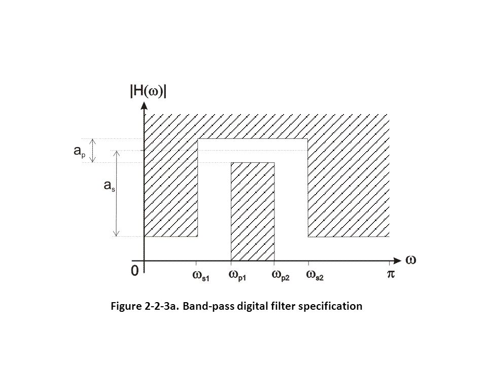
Figure 2-2-3 illustrates a band-pass filter specification. Figure 2-2-3a. Band-pass digital filter specification

8
Figure 2-2-4a. Band-stop digital filter specification

10
Transfer function of the filter is: where: b i are the feedforward filter coefficients (non-recursive part); a j are the feedback filter coefficients (recursive part); H 0 is a constant; q i are the zeros of the transfer function; and p j are the poles of the transfer function.
; a j are the feedback filter coefficients (recursive part); H 0 is a constant; q i are the zeros of the transfer function; and p j are the poles of the transfer function.")
11
The recursive part of the transfer function is actually a feedback of discrete-time system. FIR filters do not have this recursive part of the transfer function, so the expression above can be simplified in the following way: The impulse response of discrete-time system is obtained from inverse z-transform of the transfer function i.e. the transfer function of discrete-time system is actually the Z-transform of impulse response:

12
FIR filter structure

13
Digital FIR filters can not be derived from analog filters. Why? Rational analog filters cannot have a finite impulse response. Why try to get FIR design ? 1.They are inherently stable 2.They can be designed to have linear phase 3.There is great flexibility in shaping their magnitude response 4.It is easy to implement them.

14
While designing filters, it is desired to have approximately constant frequency response magnitude and zero phase in that band. For causal systems, zero-phase is not possible therefore some phase distortion must be allowed. The effect of Linear-Phase (with integer slope) is a simple time shift. A non-linear phase can have a major effect on the shape of the signal even when the frequency response magnitude is constant. Hence it is desirable to design a system with exactly or approximately linear phase.
 is a simple time shift. A non-linear phase can have a major effect on the shape of the signal even when the frequency response magnitude is constant. Hence it is desirable to design a system with exactly or approximately linear phase..")
Similar presentations


 can be.>")

 Kevin D. Donohue Electrical and Computer Engineering University of Kentucky.>")


 Filters>")


