Download presentation
Presentation is loading. Please wait.

2
Lab 2 Microprocessor MPC430F2274

3
MSP-430 Architecture

4
Types of memory ROM (read-only memory, non-volatile): –Mask-programmable: programmed by manufactory and not by user, can not be modified –Flash programmable: can be modified, all the memory is flashed and programmed again RAM (random access memory for writes): –DRAM(dynamic): each bit of data requires separate capacitor and transistor of the integrated circuit, dynamic since must be refreshed periodically otherwise info fades. –SRAM(static): does not need refresh, each bit requires six transistors
: does not need refresh, each bit requires six transistors.")
5
MSP-430 Memory Map

6
Bits, Bytes and Words in memory

7
Flash / ROM RAM See file “lnk430F2274.xcl” for more details about the memory map.

8
Memories MPC430 – 2274 has the following memory size: Flash: 32 KB RAM: 1KB

9
Peripherals Are connected to CPU through data, control and address buses using instruction set. Consist of: 1.Clock system – used by CPU and peripherals. 2.Brownout – provides internal reset signal during power off/on. 3.Digital four 8-bit I/O ports: Any combination of input, output and interrupt condition is possible. Read/write to port control registers are supported by all instructions.

10
4.Watchdog timer: Primary function is to perform system reset after a software problem occurs. If the selected time interval is expired, a systems reset is generated. If watchdog function is not needed in the application, it can perform secondary function: can be configured as interval timer and can generate interrupts after certain time interval.

11
5.Timer_a3, Timer_b3: 16 bit timer/counter with three capture/compare registers. Interrupts may be generated from counter overflow condition and from each of the capture/compare registers. 6.

12
7. 8.

13
Peripherals

15
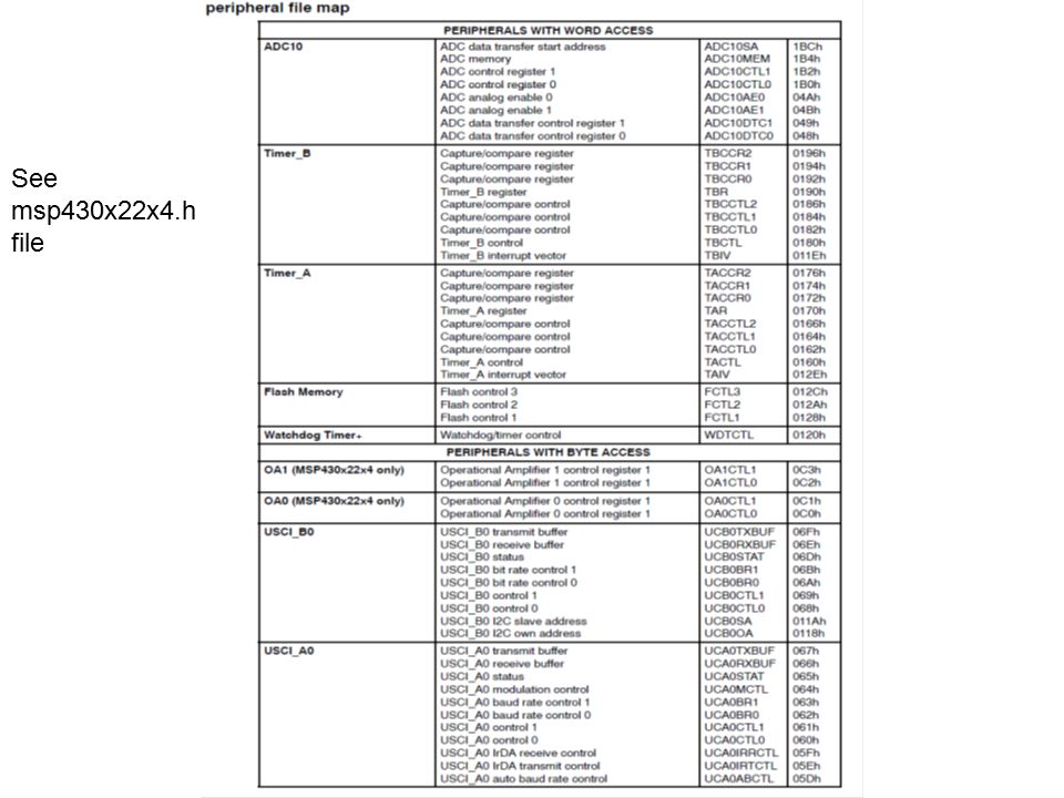
See msp430x22x4.h file

16
See msp430x22x4.h file

17
CPU

18
RISC vs. CISC Complex instruction set computer (CISC): –many addressing modes; –many operations. Reduced instruction set computer (RISC): –load/store; –pipelinable instructions.
: –load/store; –pipelinable instructions..")
19
For code efficiency, it is better to use CISC. RISC processor designed for speed and not for code size efficiency. CISC designed for code size efficiency since connects to slow devices. Compressed instruction set is stored.

20
CPU block diagram

21
Buses The system interconnect using Memory Address Bus (MAB) and Memory Data Bus (MDB)
 and Memory Data Bus (MDB)")
22
RISC 16-bit CPU

23
Exercise 1 Learn the instruction set, the addressing modes and special registers. Write the Fibonacci program that we saw in C language in the class, using assembler code. All relevant documents are on the website.

24
Interrupt I/O Busy/wait is very inefficient. –CPU can’t do other work while testing device. –Hard to do simultaneous I/O. Interrupts allow a device to change the flow of control in the CPU – allow parallelism. –Causes subroutine call to handle device.

25
Interrupt interface CPU status reg data reg mechanism PC intr request intr ack data/address IR

26
Interrupt behavior Based on subroutine call mechanism. Interrupt forces next instruction to be a subroutine call to a predetermined location. –Return address is saved to resume executing foreground program.

27
Interrupt physical interface CPU and device are connected by CPU bus. CPU and device handshake: –device asserts interrupt request; –CPU asserts interrupt acknowledge when it can handle the interrupt.

28
Example: character I/O handlers /* interrupt handlers */ void input_handler() { global_achar = peek(IN_DATA);// get char global_gotchar = TRUE;// signal to main poke(IN_STATUS,0); // reset status } void output_handler() { //nothing to do } Example: read from input and write on output
 { global_achar = peek(IN_DATA);// get char global_gotchar = TRUE;// signal to main poke(IN_STATUS,0); // reset status } void output_handler() { //nothing to do } Example: read from input and write on output")
29
Example: interrupt-driven main program main() { while (TRUE) { if (global_gotchar) { poke(OUT_DATA,global_achar); poke(OUT_STATUS,1); global_gotchar = FALSE; } Still no foreground job is executed!
 { while (TRUE) { if (global_gotchar) { poke(OUT_DATA,global_achar); poke(OUT_STATUS,1); global_gotchar = FALSE; } Still no foreground job is executed!")
30
© 2000 Morgan Kaufman Overheads for Computers as Components Example: interrupt I/O with buffers Queue for characters: headtail headtail a

31
Buffer-based input handler void input_handler() { char achar; if (full_buffer()) error = 1; else { achar = peek(IN_DATA); add_char(achar); } poke(IN_STATUS,0); if (nchars == 1) //buffer was empty until //this interrupt, no //output is waiting { poke(OUT_DATA,remove_char(); poke(OUT_STATUS,1); } }
 { char achar; if (full_buffer()) error = 1; else { achar = peek(IN_DATA); add_char(achar); } poke(IN_STATUS,0); if (nchars == 1) //buffer was empty until //this interrupt, no //output is waiting { poke(OUT_DATA,remove_char(); poke(OUT_STATUS,1); } }")
32
Buffer-based output handler void output_handler() { char achar; if (!empty_buffer()) { poke(OUT_DATA,remove_char(); poke(OUT_STATUS,1); }//turn on device }
 { char achar; if (!empty_buffer()) { poke(OUT_DATA,remove_char(); poke(OUT_STATUS,1); }//turn on device }")
33
I/O sequence diagram :foreground:input:output:queue empty a b bc c foreground job is executed!

34
Debugging interrupt code What if you forget to change registers? –Foreground program can exhibit mysterious bugs. –Bugs will be hard to repeat---depend on interrupt timing. Interrupt never occurs in the middle of instruction execution, but before it or after it.

35
Priorities and vectors Two mechanisms allow us to make interrupts more specific: –Priorities determine what interrupt gets CPU first. –Vectors determine what code is called for each type of interrupt. Mechanisms are orthogonal: most CPUs provide both.

36
Prioritized interrupts CPU device 1device 2device n L1 L2.. Ln interrupt acknowledge If all devices ask interrupt simultaneously, only the highest priority receives it

37
Interrupt prioritization Masking: interrupt with priority lower than current priority is not recognized until pending interrupt is complete. Non-maskable interrupt (NMI): highest- priority, never masked. –Often used for power-down.
: highest- priority, never masked. –Often used for power-down..")
38
Example: Prioritized I/O :interrupts:foreground:A:A:B:B:C:C B A,B C A

39
© 2000 Morgan Kaufman Interrupt vectors Allow different devices to be handled by different code. Interrupt vector table: handler 0 handler 1 handler 2 handler 3 Interrupt vector table head

40
Interrupt vector acquisition :CPU:device Receive interrupt request Receive ack receive vector Activity on the bus

41
Generic interrupt mechanism intr? N Y Assume priority selection is handled before this point. N ignore Y ack vector? Y Y N timeout? Y bus error call table[vector] intr priority > current priority? continue execution

42
Interrupts

43
Maskable interrupts Caused by peripherals with interrupt capability including watchdog. Each interrupt source can be enabled/disabled by the correspondent bit in the status register.

44
Non-Maskable Interrupt There is no need to mask the interrupt. The interrupt is reseted automatically and then set again.

47
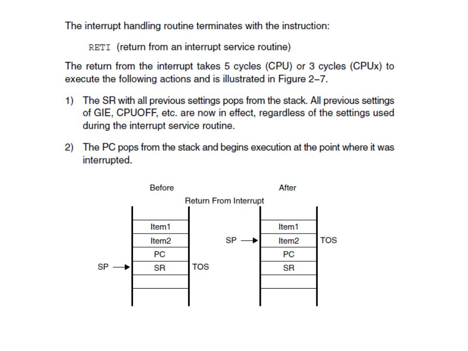
Interrupt Nesting

48
Interrupt vector table

Similar presentations


 is needed. Sources of interrupts: internal fault (e.g.. divide by.>")


