Download presentation
Presentation is loading. Please wait.

1
UNIT – III Polarization By- Dr P M Patel
Introduction: Interference and diffraction phenomena proved that light is a wave motion These phenomena are used to find wavelength of light and they do not give any indication regarding the character of waves. Interference and diffraction phenomena proved that light is a wave motion. Maxwell developed electromagnetic theory and suggested that light-waves are electromagnetic waves.

2
Electromagnetic waves are transverse waves, so it is obvious that light waves are also transverse waves. Longitudinal waves are waves in which particles of medium oscillate along the direction of propagation of wave (e.g. sound wave). Transverse waves are waves in which particles of medium oscillate perpendicular to the direction of propagation of wave. (e.g. Electromagnetic waves.) Polarization is possible in transverse wave
. Transverse waves are waves in which particles of medium oscillate perpendicular to the direction of propagation of wave. (e.g. Electromagnetic waves.) Polarization is possible in transverse wave.")
3
Unpolarized Light is the light is which the planes of vibration are symmetrically distributed about the propagation direction of the wave. Plane Polarized light is a wave in which the electric vector is everywhere confined to a single plane. A linearly polarized light wave is a wave in which the electric vector oscillates in a given constant orientation.

4
Production of Linearly Polarized Light:
Methods for producing Linearly polarized light : Reflection Refraction Scattering Selective absorption Double reflection. Applications of Polarized light: Industry and Engineering fields In liquid crystal displays (LCDs) Widely used in wristwatches, calculators, T.V. Screens optical fibers.
 Widely used in wristwatches, calculators, T.V. Screens. optical fibers.")
5
Polarization by reflection:
In 1808, E.L.Malus discovered the polarization of natural light by reflection from the surface of glass. He noticed that when natural light is incident on a plane sheet of glass at a certain angle, the reflected beam is plane polarized.

7
Brewster's Law In 1892, Brewster performed number of experiments to study the polarization of light by reflection at the surfaces of different media. He found that ordinary light is completely polarized in the plane of incidence when it gets reflected from a transparent medium at a particular angle known as the 'angle of polarization.' He proved that 'the tangent of the angle of polarization is numerically equal to the refractive index of the medium.' Also the reflected and retracted rays are perpendicular to each other.

8
If is the angle and μ is the refractive index of the medium, then
This is known as Brewster’s law.

9
Brewster found that the maximum polarization of reflected ray occurs when it is at right angles to the refracted ray. It means that According to Snell’s law, Where, is the absolute refractive index of reflecting surface is the refractive index of the surrounding medium.

10
The polarizing angle is also known as Brewster angle and denoted by

11
From Snell’s law, μ= From Brewster's law, µ=tan i = Comparing above equations, cos i = sin r = cos (π/2 - r) i = π/2 – r i+r = π/2 Therefore the reflected and the retracted rays are at right angles to each other.

12
From Brewster's law, the value of 'i' for crown glass of refractive index 1.52 is given by.
i= tan-1(1.52) i= 56.70 For ordinary glass the approximate value for the polarizing angle is 570. For a refractive index of 1.7, the polarizing angle is Thus the polarizing angle is not widely different for different glasses.
 i= For ordinary glass the approximate value for the polarizing angle is 570. For a refractive index of 1.7, the polarizing angle is Thus the polarizing angle is not widely different for different glasses.")
13
Applications of Brewster’s law
Brewster's law can be used to determine the reflective Indies of opaque materials. It is used to calculate the polarizing angle for total polarization of reflected light, if reflective index of the material is known. Brewster's angle can be utilized for transmitting a light beam in into or out of an optical fiber without reflections losses.

14
Polarization by refraction-pile of plates
When unpolarized light is incident at Brewster's angle on a smooth glass surface, the reflected light is totally polarized while the refracted light is partially polarized. If natural light is transmitted through a single plate, they it is partially polarized. If a stack of glass plates is used instead of a single plates, reflections from successive surfaces of each glass plate filter the perpendicular component from the transmitted ray. The transmitted ray consists of only parallel components.

16
Ip- Intensity of parallel component of refracted light.
Is- intensity of perpendicular component of light. Thus, degree of polarization of refracted (transmitted) light is given by where m= no. of plates required. = refractive index of material.
 light is given by. where m= no. of plates required. = refractive index of material.")
17
About 15 glass plates are required for this purpose.
The glass plates are kept inclined at an angle of 330 to the axis of the tube This arrangement is called a pile of plates. When unpolarized right is incident on the plates at Brewster angle, the transmitted light will be polarized and parallel to the plane of incidence. Drawback: The drawback of this method is good portion of light is lost in reflections.

18
Polarization by Scattering

19
If a narrow beam of natural light is incident on a transparent medium, contain a suspension of ultramicroscopic particles, the scattered light is partially polarized. The degree of polarization depends on the angle of scattering. The beam scattered at 900 with respect to the incident direction is linearly polarized

20
Sun light scattered by air molecules is polarized.
The maximum effect is observed on a clear day when the sun is near the horizon. The light reaching on the ground from directly overhead is polarized to the extent of 70% to 80%.

21
Polarization by Selective absorption
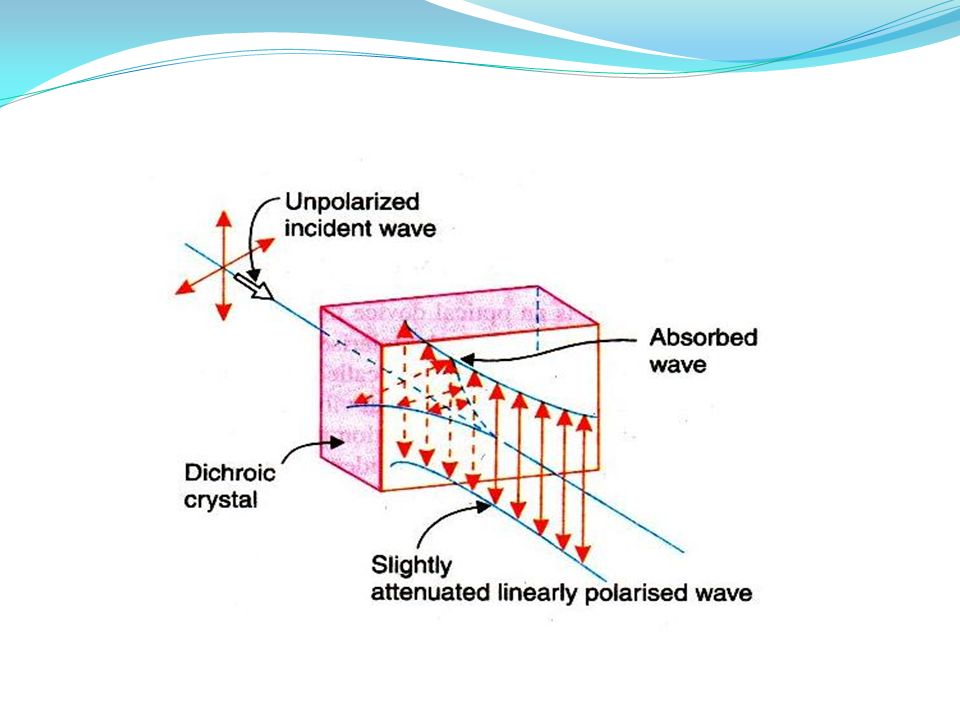
In 1815 Biot discovered that certain mineral crystal absorbs light selectively. When natural light passes through a crystal such as tourmaline, it splits into two components which are polarized in mutually perpendicular places. The crystal strongly absorbs light that is polarized in a direction parallel to a particular plane in the crystal but freely transmits the light component polarized in a perpendicular direction. This difference in the absorption for the rays is known as selective absorption or dichroism.

23
The difference in absorption in different direction may be understood from the electron theory.
When the frequency of incident light wave is close to natural frequency of the electron cloud, the light waves are absorbed strongly. Crystals that exhibit selective absorption are anisotropic. The crystal splits the incident wave in to two waves. The component having its vibration perpendicular to the principal plane of the crystal gets absorbed. The component with parallel vibrations is less absorbed and it is transmitted. The transmitted light is linearly polarized. The drawback of this method is that the crystal of bigger size cannot be grown.

24
Polarization by double refraction
This phenomenon was discovered by Erasmus Bartholinus in 1969. When light is incident on a calcite crystal, it splits into two refracted rays. This phenomenon is called double refraction or birefringence. The crystal is called birefrigent.

25
The two rays produced in double refraction are linearly polarized in mutually perpendicular directions. The ray which obeys Snell's law of refraction is known as ordinary ray or o-ray. The other ray does not obey Snell's law is called extraordinary ray or e-ray.

26
Polarizer and Analyzer
It is an optical device that transforms unpolarized light into polarized light. If it produces linearly polarized light. It is called a lineally Polarizer. If natural light is incident on a linear polarizer, only that vibration which is parallel to the transmission axis is allowed to pass through the polarizer while the vibration that is in a perpendicular direction is totally blocked.

27
Analyzer:- Analyzer is a device, which is used to find whether the light is polarized or unpolarized. Both polarizer and analyzer are fabricated in the same way and wave the same affect on the incident light.

28
NICOL'S PRISM A Nicol prism is made from calcite crystal.
It was designed by William Nicol in 1820. A calcite crystal whose length is three times as its width The end faces of this crystals are grounded in such a way that the angles in the principal section becomes 680 and 1120 instead of 710 and 1090 The crystal is cut in two pieces by a plane perpendicular to the principal section as well as the new end faces. The two parts of the crystal are then cemented together with Canada balsam. The refractive index of Canada balsam lies between the refractive indices for the ordinary and extra-ordinary rays for calcite.

29
(µ0=1.66, µe =1.486 and µCanada balms = 1.55)
")
30
Working of Nicol Prism as Polarizer and Analyzer

31
Polaroid Sheets In 1928 E.H. Laud developed a method of aligning small crystal to obtain large polarizing sheets. The sheets are called Polaroid sheets. Constructions:- A clear plastic sheet of long chain molecules of polyvinyl alcohol (PVA) is heated. It is then stretched in a given direction to many times its original length. During this process, PVA molecules become aligned along the direction of stretching.
 is heated. It is then stretched in a given direction to many times its original length. During this process, PVA molecules become aligned along the direction of stretching.")
32
The sheet is laminated to a rigid sheet of plastic.
It is then exposed to iodine vapour. The iodine atoms attach themselves to the straight long chain of PVA molecules. The conduction electrons associated with iodine can move along the chains. A sheet fabricated according to this process is known as H-sheet.

33
Polaroid Sheets as Polarizer and Analyzer

34
Fig (a) - transmission axis of the analyzer A is parallel to polarizer P so light passes through the analyzer. Fig (b) Transmission axis is at angle θ so light partially transmitted. Fig(c) When the axes are perpendicular to each other, no light is transmitted.
 Transmission axis is at angle θ so light partially transmitted. Fig(c) When the axes are perpendicular to each other, no light is transmitted.")
35
Working When natural light is incident on the sheet, the component that is parallel to the chains of iodine atoms induces current in the conducting chains and is therefore strongly absorbed. Thus the transmitted light contains only the component that is perpendicular to the direction of molecular chains. The direction of E-vector in the transmitted beam corresponds to the transmission axis of the Polaroid sheet.

36
These sheets are expensive and can be made in large sizes.
They are widely used in sunglasses, camera filters etc. to eliminate the unwanted glare from objects. They can be used as polarizer and analyzer.

37
Effect of Polarizer on Natural light:
When unpolarized light passes through a polarizer, the intensity of the transmitted light will be exactly half that of the incident light.

38
Let E0 is the amplitude of vibration of the unpolarized light incident on the polarizer.
Let E0 makes an angle with the transmission axis of the polarizer. Here E0 may be resolved into two components Ex and Ey The polarizer blocks the component Ex and transmits the component Ey. The intensity of the transmitted light

39
Intensity (Amplitude)2
Now, the value is from 0 to 2π because unpolarized light has all possible vibrations.

40
Thus, the intensity of transmitted light through the polarizer is half the intensity of incident light.

41
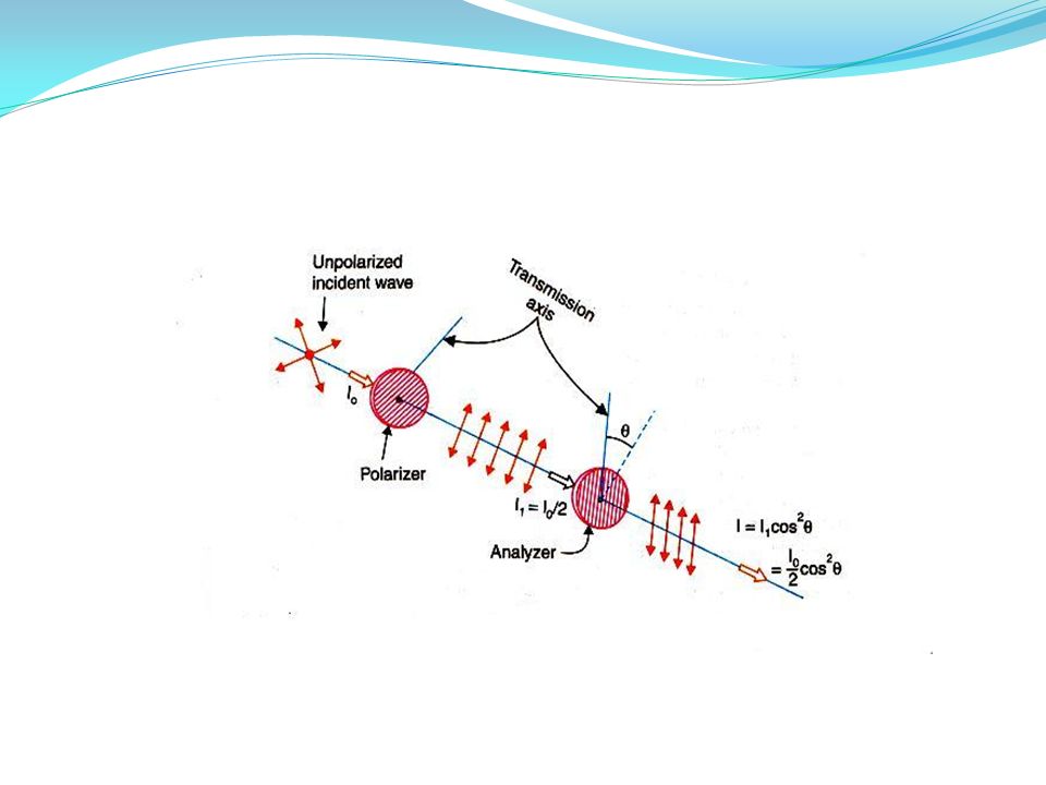
Effect of analyzer on plane polarized light- Malus law
When natural light is incident on a polarizer, the transmitted light is linearly polarized. If this light-further passes through an analyzer, the intensity varies with the angle between the transmissions axes of polarizer, and analyzer. Malus studied their phenomenon and known as Malus law. Statement: "The intensity of the polarized light transmitted through the analyzer is proportional to cosine square of the angle between the plane of transmission of the analyzer and plane of transmission of the polarizer."

43
Let I0 is the intensity of unpolarized light.
The intensity of polarized light from the polarizer is I0/2. Taking I1=I0/2. This plane polarized light then passes through the analyzer. Let E is the amplitude of vibration and is the angle between this vibration and transmission axis of an analyzer.

44
E resolves into two components
Ey parallel to the plane of transmission of the plane of analyzer, and Ex, perpendicular to the plane of analyzer. Ey component is only transmitted through the analyzer. Intensity of light for this component:

45
If, , then axis are parallel I= I1 , then axis are perpendicular I= 0 , then axis are perpendicular I= 0 Thus, there are two positions of maximum intensity and two positions of zero intensity when we rotate the axis of the analyzer with respect to that of the polarizer.

46
Anisotropic Crystals:
Isotropic Materials:- In isotopic materials, atoms are arranged in a regular periodic manner. In isotropic materials, when a light beam is incident, it refracts a single ray. It means that in such material the refractive index is same in all direction. e. g. Glass ,water and air Anisotropic Materials:- In anisotropic material, the arrangement of atoms differs in different directions within a crystal. Thus the physical properties vary like, thermal conductivity, electrical conductivity, velocity of light and refractive index etc. vary with the directions. Such crystal are then said Anisotropic.

47
The anisotropic crystals are divided into two classes.
(i)Uniaxial Crystal: In this type of crystal, one of the refracted rays is an ordinary ray and the other is an extraordinary. e. g. Calcite, tourmaline and Quartz. (ii)Biaxial Crystal: In biaxial crystal both the refracted rays are extra ordinary rays. e. g. mica, topaz & aragonite.
Uniaxial Crystal: In this type of crystal, one of the refracted rays is an ordinary ray and the other is an extraordinary. e. g. Calcite, tourmaline and Quartz. (ii)Biaxial Crystal: In biaxial crystal both the refracted rays are extra ordinary rays. e. g. mica, topaz & aragonite.")
48
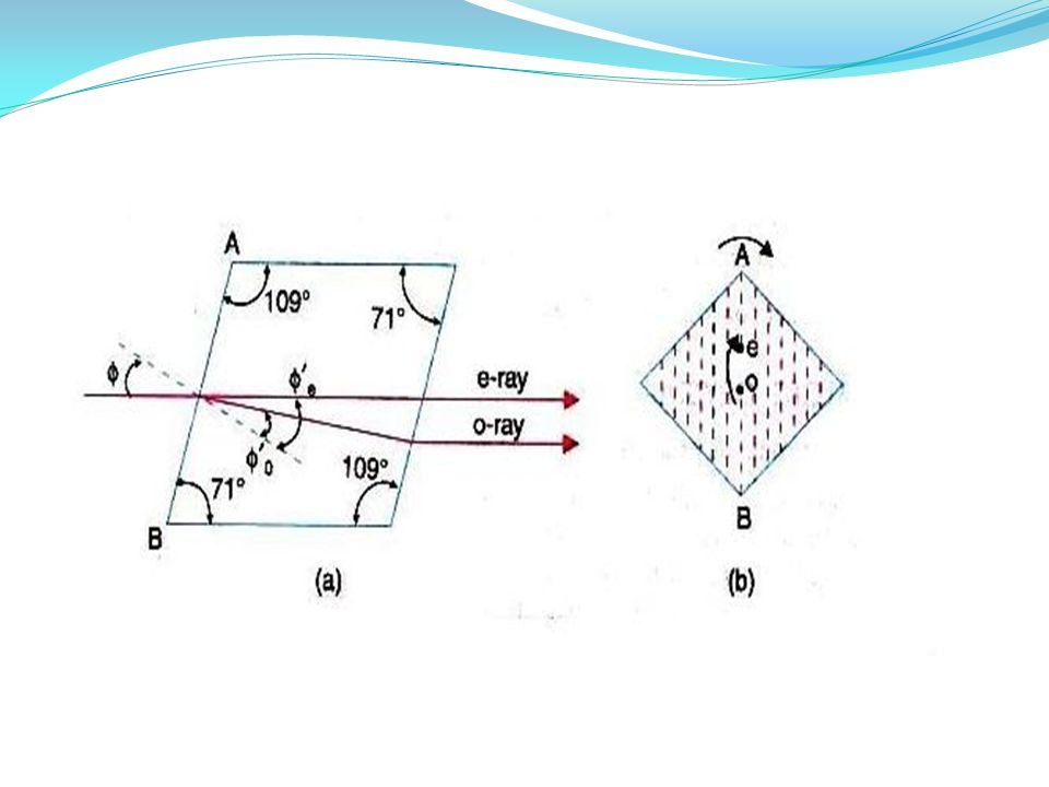
Calcite Crystal: Calcite crystal is the form of a rhombohedron bounded by six parallelograms with angles equal to 78 and 102. At two opposite corners (A&H) the three angles of faces meeting there are all obtuse (larger than 90°) These corners (A&H) are known as blunt corners. Optic axis A line passing through 'A' making equal angles with each of the three corners gives the direction of optic axis. Any line parallel to this line is also an optic axis.
 the three angles of faces meeting there are all obtuse (larger than 90°) These corners (A&H) are known as blunt corners. Optic axis. A line passing through A making equal angles with each of the three corners gives the direction of optic axis. Any line parallel to this line is also an optic axis.")
50
AH is the optic axis of calcite crystal.
If a ray of light is incident along the optic axis or in a direction parallel to the optic axis, then it will not split up into two rays. Thus the phenomenon of double refraction is absent when the light is allowed to enter the crystal along the optic axis.

51
Principal Section A plane containing the optic axis and perpendicular to a pair of opposite faces of the crystal is called the principal section of the crystal for that pair of faces. As a crystal has six faces, so far every point inside the crystal there are three principal sections, one for each pair of opposite crystal faces. A principal section cuts the crystal surfaces in a parallelogram having angles 710 and 1090

53
In fig(a) the principal section of the crystal is shown.
An end view of any principal section is a straight line (shown by dotted line in fig.b) The plane containing the optical axis and the O -ray is called the principal plane of O -ray. The plane containing the optic axis and the E-ray is called the principal plane of E-ray.
 The plane containing the optical axis and the O -ray is called the principal plane of O -ray. The plane containing the optic axis and the E-ray is called the principal plane of E-ray.")
54
Double refraction When a ray of light is refracted by a crystal of calcite it gives two refracted rays. This phenomenon is called "DOUBLE REFRACTION".

55
Positive crystal: When reflective index for extraordinary ray is greater then that of O-ray µe > µo. Negative crystal: when reflective index for extraordinary ray is lesser then that of O-ray µe < µo

56
Mark an ink dot on a piece of paper.
If we place a calcite crystal over this dot, then two images of dots are observed. Now rotate the crystal slowly as shown in figure ii. It is found that one image remains stationary and the second image rotates with the rotation of the crystal. The stationary image is known as the ordinary image The second image is known as the extraordinary image. The retracted ray which produces ordinary image is known as ordinary ray O-ray The retracted ray which produces extraordinary image is known extraordinary ray (E-ray).
.")
57
When a ray of light AB is incident in the calcite crystal making an angle of incidence i, it is refracted along two paths inside the crystal Along BC making an angle of retraction r2 and Along BD making an angle of refraction r1. These two rays emerge out along CE and DO are parallel.

58
The difference between o-ray and e-ray is given below:
The ordinary ray has a refractive index µ0 = The extraordinary ray has a refractive index µe = The o-ray obeys the laws of refraction and its refractive index is constant. For e-ray its refractive index varies with the angle of incidence and it is not fixed.

59
For the case of calcite µ0 > µe because r1less than r2.
Therefore, the velocity of light for the o-ray inside the crystal is less than the velocity of light for e-ray. µ0 = and µe = The o-ray travels in the crystal with same velocity in all directions The velocity of e-ray is different in different directions, because its refractive index varies. Both o-ray and e-ray is plane polarized. They are polarized in mutually perpendicular planes.

60
Huygens’ explanation of double refraction in uniaxial crystal
According to Huygens, the each point on a wave front acts as a fresh source of secondary wavelets. He explained the phenomena of double refraction in uniaxial crystal with the help of secondary wavelets. Theory: When any wave front strikes a doubly refraction crystal, every point of the crystal becomes a source of two wavefronts.

61
Ordinary wavefront corresponding to ordinary rays.
Since ordinary rays have same velocity in all directions, the secondary wave front is spherical. Extra-ordinary wavefront corresponding to extra-ordinary rays. Since extra-ordinary rays have different velocities in different directions, The extra-ordinary wave front is ellipsoid with optic axis as the axis of revolution.

62
The sphere and ellipsoid touch each other at points which lie on the optic axis of the crystal, because two velocity of ordinary and extra ordinary ray is same along the optic axis. In certain crystals like calcite and tourmaline called the negative crystal The ellipsoid lies outside the sphere as shown in fig.(a).
.")
64
In negative crystals, the extra-ordinary wavefront travels faster than ordinary wavefront except along optic axis. (ve> v0 and µ0> µe). In certain crystal (like quartz). Sphere lies outside the ellipsoid as shown in fig-b. Such crystals are called positive crystals. In the crystals, velocity of ordinary wavefront is greater than extraordinary wave front except along optic axis.
. In certain crystal (like quartz). Sphere lies outside the ellipsoid as shown in fig-b. Such crystals are called positive crystals. In the crystals, velocity of ordinary wavefront is greater than extraordinary wave front except along optic axis.")
65
Positive Crystal and Negative Crystal:
In positive crystals the refractive index for e-ray is greater than refractive index for o-ray i.e. µe> µo. In negative crystals the refractive index for o-ray is greater than reflective index for e-ray i.e. µ0> µe In positive crystals e-ray travels slower than o-ray in all directions except along the optic axis. V0> Ve In negative crystals o-ray travels slower than e- ray in all directions except along the optic axis i.e. V0< Ve

66
According to Huygen's, ellipse corresponding to e-ray is contained within the sphere corresponding to o-ray According to Huygen's, ellipse corresponding to e-ray lies outside the sphere corresponding to o-ray Birefringence or amount of double refraction of a crystal is defined as Δµ=µe-.µo Δµ is positive quantity for positive crystals Δµ is negative for negative crystals. Example: Quartz Example: calcite

67
Superposition of waves linearly polarized at right angles.
Let consider two light waves travelling in the x-direction One wave is polarized in x-y plane and the other is polarized y-z plane. Let us find the effect produced due to the super positions of these two waves.

69
Two waves are represented as
Where, is phase difference between two waves = frequency According to the principle of superposition,

70
From equation- (2) From equation- (1)
 From equation- (1)")
71
Rearranging above equation,
Squaring both the sides,

72
Dividing both side by E22

73
Above equation, is the general equation of ellipse
Hence, the tip of the resultant vector traces an ellipse in Y-Z plane. The ellipse is constrained within a rectangle having sides 2E1, and 2E2.

74
Special cases:- When , ,then two waves are in phase.

75
This is the equation represents a straight line, having a slope (E2/E1).
It means that, the resultant of two plane-polarized waves is again a plane-polarized wave. When The two waves are in opposite phase.

76
This equation represents a straight line of a slope (-E2/E1).
.")
77
If, This is the equation of ellipse. Its major and minor axis considers with y-and z coordinates axes. Thus the waves are out of phase by 900 and their resultant wave is elliptically polarized wave.

78
If, Then, equation (4) reduced to, This is the equation of circle. Hence result wave is circularly polarized.

79
TYPES OF POLARIZED LIGHT
Unpolarized light:- It consists of sequence of wave trains, all oriented at random. It is considered as the resultant of two optical vectors components, which are incoherent. Linearly polarized light:- It can be regarded as a resultant of two coherent linearly polarized waves. Partially polarized light:- It is a mixture of linearly polarized light and unpolarized light.

80
Elliptically polarized light:-
It is the resultant of two coherent waves having different amplitudes and a constant phase difference of 900. In elliptically polarized light, the magnitude of electric vector E rotates about the direction of propagation. If light is coming towards us, we would observe that tip of the E vector traces an ellipse. The side view of E vector gives flattered helix in space.

81
If we look from the source and rotation of E vector is clockwise then it is right elliptically polarized wave. If it is anti clock wise then it is left elliptically polarized wave.

82
Circularly polarized light:-
It is the resultant of two coherent waves having same amplitudes and a constant phase difference of 900. In this type of light the magnitude of E vector remains constant.

83
If light is coming towards us, we would observe that tip of the E vector trances a circle.
If we look from the source and rotation E vector is clockwise then it is said right circularly polarized and if it anticlockwise then it is left circularly polarized wave.

84
Liquid Crystal Display (LCD)
Liquid crystal Display is most widely used device which makes the use of polarization. It is used in wristwatches, calculators, clocks, electronic instruments, video games etc.

85
Construction An LCD consists of liquid crystal material of 10m thickness. It is double refracting material. This material is supported between thing glass plates. The inner surfaces of thin glass are coated with transparent conducting material. This conducting material is etched in the form of a digit or character as shown in fig.2. The assembly of glass plates with liquid crystal material is sandwiched between two crossed polarizer sheets.

86
Working

87
During fabrication of LCD, the liquid crystal molecules are arranged as shown in fig.3.
This arrangement of molecules is called twisted molecular arrangement i.e Rotation from plate A to B. When natural light is incident on the LCD, the front polarizer converts it into linearly polarized light. When this polarized light propagates through LCD, the optical vector is rotated by 900 because of twisted molecular arrangement. This light passes very easily through the rear polarizer whose transmission axis is perpendicular to that of the front polarizer.

88
A reflecting coating at the back of the rear polarizer sends back the light, which comes out from the front polarizer. The display seems illuminated uniformly. When a voltage is applied to the device, the molecules between the electrodes align along the directions of field. When light passes through this region optical vector does not undergo rotation. The rear polarizer blocks the light and therefore a dark digit or character is seen in that region as shown in figure.

89
Thank You

Similar presentations


 Ltd. 9.4 Polarization of light waves Polarization by selective absorption Polarization by reflection Polarization by reflection.>")

 2.>")


 Phase shift -_____ (if n 2 > n 1 ) If there is a very thin film of material – a few wavelengths.>")
>")


