Download presentation
Presentation is loading. Please wait.

1
R.HARIHARAN LECT/EEE UNIT - V

2
In this section, different overvoltage tests done on insulators and bushings are discussed. The overvoltage tests are classified into two groups: ◦ (i) power frequency voltage tests; and ◦ (ii) impulse voltage tests. These tests together ensure the overvoltage withstand capability of an apparatus. Before discussing the actual tests, to know the general terminology of the technical terms used is essential.
 power frequency voltage tests; and ◦ (ii) impulse voltage tests. These tests together ensure the overvoltage withstand capability of an apparatus. Before discussing the actual tests, to know the general terminology of the technical terms used is essential..")
3
Disruptive Discharge Voltage This is defined as the voltage which produces the loss of dielectric strength of an insulation. It is that voltage at which the electrical stress in the insulation causes a failure which includes the collapse of voltage and passage of current. In solids, this causes a permanent loss of strength, and in liquids or gases only temporary loss may be caused. When a discharge takes place between two electrodes in a gas or a liquid or over a solid surface in air, it is called fiashover. If the discharge occurs through a solid insulation it is called puncture.

4
Withstand Voltage The voltage which has to be applied to a test object under specified conditions in a withstand test is called the withstand voltage. Fifty Per Cent Flashover Voltage This is the voltage which has a probability of 50% flashover, when applied to a test object. This is normally applied in impulse tests in which the loss of insulation strength is temporary.

5
Hundred Per Cent Flashover Voltage The voltage that causes a flashover at each of its applications under specified conditions when applied to test objects is specified as hundred per cent flashover voltage. Creepage Distance It is the shortest distance on the contour of the external surface of the insulator unit or between two metal fittings on the insulator.

6
D.C. Test Voltages Alternating test voltages of power frequency should have a frequency range of 40 to 60 Hz and should be approximately sinusoidal. The deviation allowed from the standard sine curve is about 7%. The deviation is checked by measuring instantaneous values over specified intervals and computing the rms value, the average value, and the form factor.

7
Impulse Voltages Impulse voltages are characterized by polarity, peak value, time to front (/y), and time to half the peak value after the peak (tt). The time to front is defined as 1.67 times to time between 30% and 90% of the peak value in the rising portion of the wave.

8
The tests that are normally conducted are usually subdivided as ◦ (i) type tests, and ◦ (ii) the routine tests. Type tests are intended to prove or check the design features and the quality. The routine tests are intended to check the quality of the individual test piece. Type tests are done on samples when new designs or design changes are introduced, whereas the routine tests are done to ensure the reliability of the individual test objects and quality and consistency of the materials used in their manufacture. High voltage tests include (i) the power frequency tests, and (ii) impulse tests. All the insulators are tested for both categories of test.
 the power frequency tests, and (ii) impulse tests. All the insulators are tested for both categories of test..")
9
Dry and Wet Flashover Tests frequency is applied across the insulator and increased at a uniform rate of about 2 percent per second of 75% of the estimated test voltage, to such a value that a breakdown occurs along the surface of the insulator. If the,test is conducted under normal conditions without any rain or precipitation, it is called "dry flashover test".

10
Wet and Dry Withstand Tests specified in the relevant specification is applied under dry or wet conditions for a period of one minute with an insulator mounted as in service conditions. The test piece should withstand the specified voltage.

11
Impulse Withstand Voltage Test This test is done by applying standard impulse voltage of specified value under dry conditions with both positive and negative polarities of the wave. If five consecutive waves do not cause a flashover or puncture, the insulator is deemed to have passed the test. If two applications cause flashover, the object is deemed to have failed. If there is only one failure, additional ten applications of the voltage wave are made. If the test object has withstood the subsequent applications, it is said to have passed the test.

12
Impulse Flashover Test The test is done as above with the specified voltage. Usually, the probability of failure is determined for 40% and 60% failure values or 20% and 80% failure values, since it is difficult to adjust the test voltage for the exact 50% flashover values. The average value of the upper and the lower limits is taken The insulator surface should not be damaged by these tests, but slight marking on its surface or chipping off of the cement is allowed.

13
Power Factor—Voltage Test In this test, the bushing is set up as in service or immersed in oil. It is connected such that the line conductor goes to the high voltage side and the tank or earth portion goes to the detector side of the high voltage Schcring bridge. Voltage is applied up to the line value in increasing steps and then reduced. The capacitance and power factor (or tan 5) are recorded at each step. The characteristic of power factor or tan 8 versus applied voltage is drawn. This is a normal routine test but sometimes may be conducted on percentage basis.
 are recorded at each step. The characteristic of power factor or tan 8 versus applied voltage is drawn. This is a normal routine test but sometimes may be conducted on percentage basis..")
14
Internal or Partial Discharge Test This test is intended to find the deterioration or failure due to internal discharges caused in the composite insulation of the bushing. This is done by using internal or partial discharge arrangement (see Sec. 9.4). The voltage versus discharge magnitude as well as the quadratic rate gives an excellent record of the performance of the bushing in service. This is now a routine test for high voltage bushings.
. The voltage versus discharge magnitude as well as the quadratic rate gives an excellent record of the performance of the bushing in service. This is now a routine test for high voltage bushings..")
15
Momentary Withstand Test at Power Frequency This is done as per the Indian Standard Specifications, IS: 2099, applied to bushings. The test voltage is specified in the specifications. The bushing has to withstand without flashover or puncture for a minimum time (~ 3Os) to measure the voltage. At present this test is replaced by the impulse withstand test.
 to measure the voltage. At present this test is replaced by the impulse withstand test..")
16
Full Wave Withstand Test The bushing is tested for either polarity voltages as per the specifications. Five consecutive full waves of standard waveform are applied, and, if two of them cause flashover, the bushing is said to have failed in the test. If only one flashover occurs, ten additional applications are done. The bushing is considered to have passed the test if no flashover occurs in subsequent applications.

17
Chopped Wave Withstand and Switching Surge Tests The chopped wave lest is sometimes done for high voltage bushings (220 kV and 400 kV and above). Switching surge flashover test of specified value is now-a-days included for high voltage bushings. The tests are carried out similar to full wave withstand tests.

18
An isolator or a disconnector is a mechanical switching device, which provides in the open position, an isolating distance in accordance with special requirements. An isolator is capable of opening and closing a circuit when either negligible current is broken or made or when no significant change in the voltage across the terminals of each of the poles of the isolator occurs. It is also capable of carrying currents under normal circuit conditions, and carrying for a specified time, currents under abnormal conditions such as those of a short circuit.

19
Testing of circuit breakers is intended to evaluate (a) the constructional and operational characteristics, and (b) the electrical characteristics of the circuit which the switch or the breaker has to interrupt or make. The different characteristics of a circuit breaker or a switch may be summarized as per the following groups.

20
Dielectric tests consist of overvoltage withstand tests of power frequency, lightning and switching impulse voltages. Tests are done for both internal and external insulation with the switch or circuit breaker in both the open and closed positions. In the open position, the test voltage levels are 15% higher than the test voltages used when the breaker is in closed position. As such there is always the possibility of line to ground flashover. To avoid this, the circuit breaker is mounted on insulators above the ground, and hence the insulation level of the body of the circuit breaker is raised.

21
The impulse tests The lightning impulse wave of standard shape are done in a similar manner as in the case of insulators. In addition, the switching surge tests with switching overvoltages are done on circuit breakers and isolators to assess their performance under overvoltages due to switching operations.

22
Direct Tests using a short circuit generator as the source using the power utility system or network as the source. Synthetic Tests Direct Testing in the Networks or in the Fields Circuit breakers are sometimes tested for their ability to make or break the circuit under normal load conditions or under short circuit conditions in the network itself. This is done during period of limited energy consumption or when the electrical energy is diverted to other sections of the network which are not connected to the circuit under test.

23
Direct Testing in Short Circuit Test Laboratories In order to test the circuit breakers at different voltages and at different short circuit currents, short circuit laboratories are provided. The schematic layout of a short circuit testing laboratory is given in Fig. 10.3. It consists of a short circuit generator in association with a master circuit breaker, resistors, reactors and measuring devices. A make switch initiates the short circuit and the master circuit breaker isolates the test device from the source at the end of a predetermined time set on a test sequence controller. Also, the master circuit breaker can be tripped if the test device fails to operate properly. Short circuit generators with induction motors as prime movers are also available.

24
Synthetic Testing of Circuit Breakers Due to very high interrupting capacities of circuit breakers, it is not economical to have a single source to provide the required short circuit and the rated voltage. Hence, the effect of a short circuit is obtained as regards to the intensity of the current and the recovery voltage as a combination of the effects of two sources, one of which supplies the a.c. current and the other the high voltage.

25
High Voltage d.c, tests are performed using cascaded rectifiers. Careful consideration is necessary when tests on polluted insulation are to be performed which require currents of 50 of 200 mA, but strong predischarge streamers of 0.5 to 1.0 A of milliseconds duration may occur. Hence, the generator must have adequate internal reactance in order to maintain the test voltage without too high a voltage drop. The voltage ratings are given in Table 11.4, and the power rating may vary from a few kW a few hundred kW.

26
It is known that the flashover voltage of an insulator in air or oil or in some fluid depends on the capacitance of the supply system, due to the fact that a voltage drop may not maintain the predischarges before breakdown. Hence, a minimum of about 1000 pF or more in parallel with the energized insulator is needed to determine the real flashover or puncture voltage, and the generator has to supply at least 1A in the case of clean and S A in the case of polluted insulator at test voltage on short circuit.

27
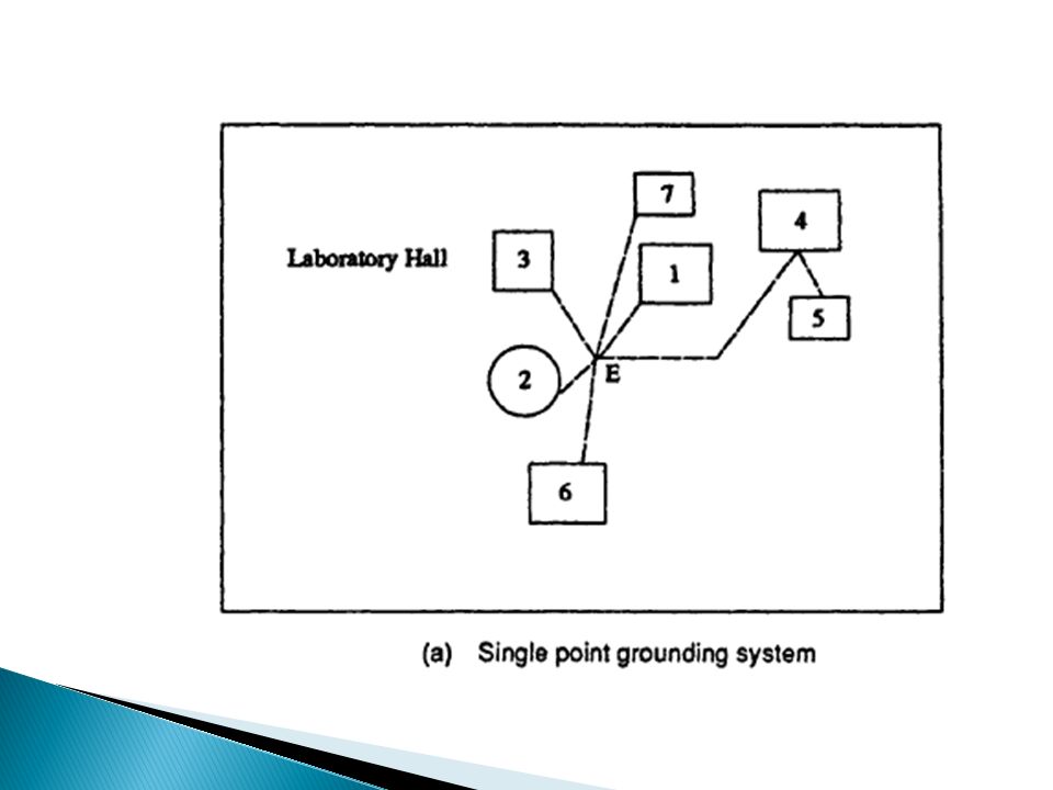
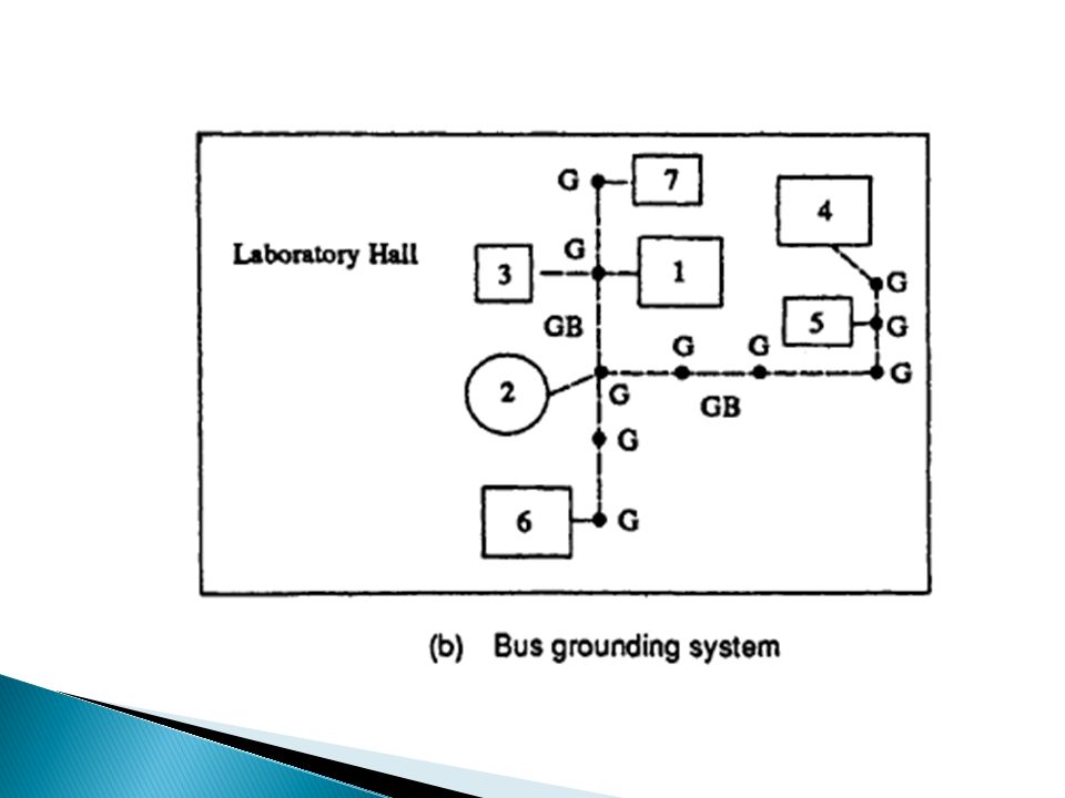
An earth or ground system means an established stable reference potential normally taken to be zero potential. There are three types of grounds (i) the idea! ground, (//) single point ground (Fig. 113a), and (IM) the bus ground (Fig. 11.3b). Of all these, the best ground is the ideal ground which cannot be realized in practice. The next preferred ground is the single point ground, and the bus ground is least satisfactory. Ideal ground can be approximated by an equipotential plane realized by a finite conducting material. The laboratory is covered by a sheet of copper metal welded into a single unit But this is very costly and is used rarely. A single point ground is commonly used. In this (see Fig. 11.3a) an earthing grid is installed within the laboratory floor, and connection from the grid is given by a large sized copper conductor to a point identified as a common ground point.
 the idea. ground, (//) single point ground (Fig. 113a), and (IM) the bus ground (Fig. 11.3b). Of all these, the best ground is the ideal ground which cannot be realized in practice. The next preferred ground is the single point ground, and the bus ground is least satisfactory. Ideal ground can be approximated by an equipotential plane realized by a finite conducting material. The laboratory is covered by a sheet of copper metal welded into a single unit But this is very costly and is used rarely. A single point ground is commonly used. In this (see Fig. 11.3a) an earthing grid is installed within the laboratory floor, and connection from the grid is given by a large sized copper conductor to a point identified as a common ground point..")
30
A typical good earthing system consists of a copper network with meshes of 1 m width laid down below the ground level around the impulse test area and well connected. This network is extended over the entire area comprising all equipment such as testing transformers, charging h.v. rectifier set, lest bay, etc. The grid should be electrically connected to all the metallic frames and reinforcing iron in the concrete walls and pillars of the building at their bottom points.

31
Impulse test area must be provided with a spread, stretched, or expanded copper grid on the floor of thickness of about 2 mm with ground rods driven into the earth to a depth equal to the height of the impulse generator. The rods are welded to the inside copper grid as well as surface copper grid. Earth connection facility is to be provided for every 16 sq. m area so that shortest lead can be used from any position inside the laboratory.

32
Where ionization measurements are to be made, the earthing system should keep the RIV level from external sources to the lowest value. In addition, the high frequency energy produced during impulse tests should not cause any trouble around the test area. If this is to be met the entire laboratory should be built into a Faraday cage.

33
The high voltage laboratory must be earthed to protect the equipment against the lightning strokes, and to protect the equipment from short circuits inside the laboratory from the power supply source. If not properly earthed, these will give rise to potentials which are different at different points in the laboratory thus causing unnecessary danger to human life and damage to the equipment.

34
The acoustical attenuation of the building is also important. It is necessary in large laboratories to have comfortable and clear communication between persons at different locations inside the laboratory. Reverberation inside the laboratory should be avoided. To get the desired effect, the laboratory should have perforated holes and fiberglass or some such material fixed to the walls. The above aspects need careful consideration in the design of a high voltage laboratory.

Similar presentations


>")


 shielding the overhead lines.>")


 M.E (ELECTRONICS SYSTEM ENGG:) MUET JAMSHORO 1 CAPACITOR.>")
