Download presentation
Presentation is loading. Please wait.

1
5-3-1 Load and line regulation

2
Learning Objectives: At the end of this topic you will be able to; explain what is meant by the terms load regulation and line regulation; Recall the use of a Zener Diode to provide a regulated voltage supply.

3
Introduction to Power Supplies The national electricity distribution system uses AC (alternating current) delivered at high voltage. Electronic systems usually require electrical energy delivered as DC (direct current) at relatively low voltages.
 at relatively low voltages..")
4
The first process uses a transformer, but this is outside the scope of this course. The second process was covered in module ET2, section 2.4.2, which looked at both half-wave and full-wave rectification. The third process uses a large value electrolytic capacitor, and was the subject of ET2 section 2.4.3. Line regulation was introduced in ET2 section 2.4.4, though not explicitly. The focus of that section was voltage regulation using a zener diode. Load regulation will also be defined and covered in one of the following sections. The remaining two processes, providing over-voltage protection and short- circuit protection, are outside the scope of the course.

5
Line and Load Regulation Ideally, a power supply should deliver a constant output voltage regardless of any changes that take place in the input or output circuits. In particular, the mains supply voltage, (the line voltage,) increases and decreases significantly depending on national factors such as demand (weather conditions, ‘Coronation Street’, FA Cup Final, ‘X Factor’ etc.) The output voltage of the power supply should ignore these changes. Line regulation measures how successfully the power supply does this. Here is a useful definition of line regulation: Line regulation is a measure of the ability of the power supply to maintain a steady output voltage when the input line voltage changes. It is expressed as the percentage change in the output voltage relative to the change in the input line voltage.
 increases and decreases significantly depending on national factors such as demand (weather conditions, ‘Coronation Street’, FA Cup Final, ‘X Factor’ etc.) The output voltage of the power supply should ignore these changes. Line regulation measures how successfully the power supply does this. Here is a useful definition of line regulation: Line regulation is a measure of the ability of the power supply to maintain a steady output voltage when the input line voltage changes. It is expressed as the percentage change in the output voltage relative to the change in the input line voltage..")
6
When the load attached to the output of a power supply is changed, the current through it changes, and this can cause a change in the power supply output voltage. When the power supply is used to deliver a steady voltage, it behaves as if there is an internal resistor in series with the load. When the output current, I OUT, increases, the voltage dropped across this internal resistor increases, and the output voltage, V OUT, seen by the load, decreases. Load regulation measures how successful the power supply is in ignoring changes in the load. Now a useful definition of load regulation: Load regulation is a measure of the ability of the output voltage to remain constant when the output current changes due to a change in the load.

7
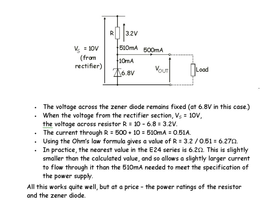
A reminder about the zener diode voltage regulator: Section 2.4.4 of ET2 looked at the properties of the zener diode, and its use as a voltage regulator. An example: A simple power supply is designed to deliver output currents up to 500mA with an output voltage of 6.8V, (even if the line voltage, and so V S, changes.) The diagram shows the currents and voltages when the output current is at its maximum value, 500mA. A current of 10mA flows through the zener diode to keep it in zener breakdown
 The diagram shows the currents and voltages when the output current is at its maximum value, 500mA. A current of 10mA flows through the zener diode to keep it in zener breakdown.")
9
The zener diode dissipates most power when the output current is zero, i.e. when no load is connected to the power supply. The next diagram shows this situation. As a result, using P = I x V,: the power dissipated in the resistor = 0.52 x 3.2 = 1.66W. the power dissipated in the zener diode = 0.52 x 6.8 = 3.54W.

10
Exercise 1 (The solutions are given at the end of the topic.) Design a simple power supply, capable of delivering up to 1A, with an output voltage of 10V. The input voltage is 13V. You need to calculate the resistance and power rating of the resistor, and the power rating of the 10V zener diode used in the circuit. Assume a current of 10mA flows through the zener diode to keep it in zener breakdown. The performance of this voltage regulator can be improved by incorporating an emitter follower into the output circuit. The next section introduces the emitter follower.

11
Solutions to Exercise:Here is the circuit diagram: The design uses a 10V zener diode. Voltage across resistor R = 13 – 10 = 3V. Current through R = 1.01A. Hence R = 3 / 1.01 = 2.97 . (The nearest lower value is 2.7 .) Using P = I x V, the power rating for R is 1.01 x 3 = 3.03W Under no load, all the current (1010mA = 1.01A) flows through the zener. Hence power rating for the zener is 1.01 x 10 = 10.1W.
 Using P = I x V, the power rating for R is 1.01 x 3 = 3.03W Under no load, all the current (1010mA = 1.01A) flows through the zener. Hence power rating for the zener is 1.01 x 10 = 10.1W..")
Similar presentations

 Reverse bias (off)>")


