Download presentation
Presentation is loading. Please wait.

1
Warm linac simulations (DTL) and errors analysis M. Comunian F. Grespan
 and errors analysis M. Comunian F. Grespan")
2
Outline Definition and requirements for errors study. Impact of the Input conditions. Impact of 2D vs 3D space charge calculation. DTL Sensitivity to input beam. Conclusions and open questions.

3
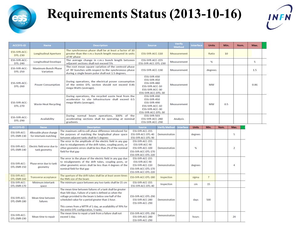
Requirements Status (2013-10-16)
")
5
Issues with the requirements for the errors study Level 3, Transverse Beam Emittance we are using 0.28 mmmrad as reference, is missing the value for the 99% emittance. Level 3, Transverse and Longitudinal Emittance Growth is written at 5%, but with Mamad we are relaxed it at 10%, is this update reported? (10% by design +10% by errors) Level 3, Transverse Aperture In the actual design is less than 6 not 10 as required, is this ok? Level 3, Transverse Beam Envelope Why this requirements? (respected but first periods). Level 3, Longitudinal Aperture we can respect the limit only the last 2 tanks. Level 4, Transverse acceptance the actual definition is not so clear: is it the ratio of Max aperture/RMS aperture (already specified) or the ratio Max emittance / RMS emittance (not defined)? What about the limit on power losses? What about the input distribution? (Is the MEBT fully defined?)
 Level 3, Transverse Aperture In the actual design is less than 6 not 10 as required, is this ok. Level 3, Transverse Beam Envelope Why this requirements. (respected but first periods). Level 3, Longitudinal Aperture we can respect the limit only the last 2 tanks. Level 4, Transverse acceptance the actual definition is not so clear: is it the ratio of Max aperture/RMS aperture (already specified) or the ratio Max emittance / RMS emittance (not defined). What about the limit on power losses. What about the input distribution. (Is the MEBT fully defined ).")
6
Method used for Errors Study Agreement with Mamad about the parameters and conditions: – MEBT output as DTL input distribution. (? MEBT DESIGN) – 11/2013: Δε with error < Δε without error + 10%. (Still valid?) – 4/2014: Δε with error < 10%. (VERY DEMANDING) – 99% of the cases should have an emittance growth less than the aforementioned Δε with error. – Each error, misalignment, rotation, gradient, …, should be studied independently to set the tolerances, while sum of the errors should still result in a linac with an emittance increase below the limit. – Power loss below 1W/m for Energy > 30 MeV. – Use of Steerers/BPM to get the results.
 – 11/2013: Δε with error < Δε without error + 10%. (Still valid ) – 4/2014: Δε with error < 10%. (VERY DEMANDING) – 99% of the cases should have an emittance growth less than the aforementioned Δε with error. – Each error, misalignment, rotation, gradient, …, should be studied independently to set the tolerances, while sum of the errors should still result in a linac with an emittance increase below the limit. – Power loss below 1W/m for Energy > 30 MeV. – Use of Steerers/BPM to get the results..")
7
Interface MEBT DTL DTL physical beginning is fixed 55mm behind the inner surface of the DTL flange. This drift takes into account the PMQ fringe field. The input beam parameters are defined at this point.

8
TraceWin debug/improvements

9
TraceWin Space Charge Calculation (SC)
")
10
Still bugs in picnic2D 3D ?

11
IFMIF SC 2D 3D ~ 4% diff 2D: 8x16 3D: 8x8x16

12
ESS MEBT SC 2D 3D ~ 3% diff 3D: 20x20x10 2D: 20x10

13
ESS DTL SC 2D 3D: no diff 2D: 20x40 3D: 20x20x40 Nominal DTL with Gaussian distribution as input (3 σ; Np=250 000)
")
14
DTL Input distribution effects Gauss MEBT Uniform All distribution with MEBT (2014.V0) Twiss parameters
 Twiss parameters")
15
DTL Ey emittance increase (Worst case) MEBT 2D MEBT 3D Gauss Uniform
 MEBT 2D MEBT 3D Gauss Uniform")
16
Nominal DTL emittance increase DistributionΔEx RMS [%]ΔEy RMS [%]ΔEz RMS [%] Nominal Uniform221 Nominal Gaussian (3σ)773 Gaussian with MEBT Twiss parameters* 3126 MEBT 2D SC1114 MEBT 3D SC564 Nominal Input RMS Emittance: Transverse=0.28 π. mm.mrad Longitudinal = 0.36 π.mm.mrad =0.1436 π deg MeV. *Mismatch Effects
![Nominal DTL emittance increase DistributionΔEx RMS [%]ΔEy RMS [%]ΔEz RMS [%] Nominal Uniform221 Nominal Gaussian (3σ)773 Gaussian with MEBT Twiss parameters* 3126 MEBT 2D SC1114 MEBT 3D SC564 Nominal Input RMS Emittance: Transverse=0.28 π.](http://images.slideplayer.com/35/10355626/slides/slide_16.jpg "mm.mrad Longitudinal = 0.36 π.mm.mrad = π deg MeV. *Mismatch Effects.")
17
DTL Sensitivity to input beam and PMQ Mismatch. Emittance change. Beam off-center. PMQ position.

18
Mismatch definitions Wangler Definition TraceWin Definition TraceWin MismatchWangler MxWangler MyWangler Mz 10%35%50%22% 20%76%117%44% 30%121%200%66% 40%172%291%87% 50%226%392%107%

19
Mismatch Values from MEBT Twiss Parameters MEBT (MEBT.2014.v0_nom) DTL nominal inputMismatch TraceWin Mismatch Wangler Alfa X1.68581.8859-5.5%16% Beta X [mm/Pi.mrad]0.28640.3173-5%16% Eps X RMS norm. [Pi.mmmrad] 0.29280.2800-- Alfa Y-3.1856-3.6187-6.2%19% Beta Y [mm/Pi.mrad]0.51330.5688-5%19% Eps Y RMS norm. [Pi.mmmrad] 0.26950.2800-- Alfa Z0.69500.338643%35% Beta Z [mm/Pi.mrad]0.57330.426217%35% Eps Z RMS norm. [Pi.mmmrad] 0.38860.3900--
![Mismatch Values from MEBT Twiss Parameters MEBT (MEBT.2014.v0_nom) DTL nominal inputMismatch TraceWin Mismatch Wangler Alfa X %16% Beta X [mm/Pi.mrad] %16% Eps X RMS norm.](http://images.slideplayer.com/35/10355626/slides/slide_19.jpg "[Pi.mmmrad] Alfa Y %19% Beta Y [mm/Pi.mrad] %19% Eps Y RMS norm. [Pi.mmmrad] Alfa Z %35% Beta Z [mm/Pi.mrad] %35% Eps Z RMS norm. [Pi.mmmrad]")
20
Effects of AlfaZ MEBT The limit of 10% emittance increase, respect the input emittance, is obtained with Alfa Z outside the range of 0 to 0.9. All the runs are without losses. The matched value for Alfa Z is around 0.4, all the other Twiss parameters are at the nominal values

21
Effects of BetaZ MEBT The limit of 10% emittance increase, respect the input emittance, is obtained with Beta Z outside the range of 0.3 to 0.6 mm/Pi.mrad. All the runs are without losses. The matched value for Beta Z is around 0.43 mm/Pi.mrad, all the other Twiss parameters are at the nominal values.

22
Mismatch X,Y,Z with gaussian beam input In the Figure the limit of 10% emittance increase, respect the input emittance, is obtained with around 10% of TraceWin mismatch, i.e. with an equivalent value of (35,50,22)% Wangler mismatch, the runs with TraceWin mismatch of more than 27% are with losses.
% Wangler mismatch, the runs with TraceWin mismatch of more than 27% are with losses..")
23
Emittance change X and Y The input emittance on both planes X, Y is increased. The 10% of output emittance increase, respect the input emittance, is reached for X, Y input emittance below of 0.26 mmmrad. All the runs are without losses.

24
Final Emittance vs input emittance Very linear response of output emittance respect to the input emittance.

25
Single emittance change X The 10% emittance increase, respect the input emittance, is reached for X input emittance outside the range of 0.27 – 0.29 mmmrad. All the runs are without losses. The output input emittance behavior is very linear. The most sensible parameter is the change on a single emittance, due to the emittance exchange phenomena.

26
Single Beam Displacement X;Y The limit of 10% emittance increase, respect the input emittance, is obtained with around 0.3 mm of beam displacement on X and 0.2 mm on Y, all the runs are without losses.

27
Only PMQ displacement without steeres The simulation has been done with 50000 macroparticles in a Gaussian input distribution cut at 3σ and with a statistics of 500 runs. The limit of 10% of emittance increase is with an error on PMQ of about 0.04 mm. The runs are with losses for an error on PMQ position of more than 0.08 mm.

28
PMQ displacement of +/- 0.04 mm Ex growth=8.5+2.7*0.93=11 % (99% of runs below 11% of emittance growth).
.")
29
Conclusions and open questions Requirements on the emittance growth range? (or max emittance?). Need to define the input distribution of DTL, i.e. the MEBT output acceptance values as baseline for errors study. Essential to define the interface line from MEBT to DTL and from DTL to HEBT. TraceWin is still with bugs on SC calculation. The DTL errors study can be done only after the definition of the previous points.
. Need to define the input distribution of DTL, i.e. the MEBT output acceptance values as baseline for errors study. Essential to define the interface line from MEBT to DTL and from DTL to HEBT. TraceWin is still with bugs on SC calculation. The DTL errors study can be done only after the definition of the previous points..")
30
Space-charge Force All use PIC method LINAC: 3D (PICNIC); 3 space-charge kicks per cell PARTRAN: 3D (PICNIC); 1 kick per cell (can use any no.) PARMILA: 2D (SCHEFF); 1 kick per cell (can use any no.) PARMELA: 3D; 12 kicks per cell (can use any no.) IMPACT: 3D; 10 kicks per cell (can use any no.)
; 3 space-charge kicks per cell PARTRAN: 3D (PICNIC); 1 kick per cell (can use any no.) PARMILA: 2D (SCHEFF); 1 kick per cell (can use any no.) PARMELA: 3D; 12 kicks per cell (can use any no.) IMPACT: 3D; 10 kicks per cell (can use any no.)")
31
SCHEFF: picnir 2D The SCHEFF subroutine is widely used for applying space-charge impulses in many beam-dynamics codes It is a particle-in-cell (PIC) code that calculates the electric field components, E r and E z, on a two-dimensional (2D) r-z grid, and interpolates these field components to get the force on each particle For purposes of calculating the space-charge fields, each particle is considered to be a ring of charge. The elliptical cross section on the x-y plane is taken into account when calculating the effective radius of the rings of charge The amount of charge in each rectangular box of the grid is then determined. E r and E z are calculated at every node in the vicinity of the beam The ellipticity of the beam cross section is taken into account when applying to each particle the impulse due to E r. The x’, y’ and longitudinal energy of each particle is changed by applying the E r and E z for a given time or distance interval Relativistic corrections are made for transforming the beam coordinates from the lab frame to the beam frame and back again

32
PICNIC 3D The PICNIC (Particle In Cell Numerical Integration between Cube) is a full 3D code As in PICNIR, it applies the space charge impulses to a beam at a given z or time Particles in each cube formed by the 3D grid are counted The field is calculated at each node of the grid as the sum of the contributions from all the grid-cubes, each of which is assumed to be uniformly populated The field at the position of the particle is interpolated from the neighboring nodes, allowing a calculation of space-charge impulse The field acting on particles outside the mesh is the one of a Gaussian beam with the same RMS dimensions as the real beam Relativistic corrections are made by transforming the beam-coordinates from the lab frame to the beam frame and back again The mesh size is adjusted to 3 times the RMS beam-size in all directions (DEFAULT)
 is a full 3D code As in PICNIR, it applies the space charge impulses to a beam at a given z or time Particles in each cube formed by the 3D grid are counted The field is calculated at each node of the grid as the sum of the contributions from all the grid-cubes, each of which is assumed to be uniformly populated The field at the position of the particle is interpolated from the neighboring nodes, allowing a calculation of space-charge impulse The field acting on particles outside the mesh is the one of a Gaussian beam with the same RMS dimensions as the real beam Relativistic corrections are made by transforming the beam-coordinates from the lab frame to the beam frame and back again The mesh size is adjusted to 3 times the RMS beam-size in all directions (DEFAULT)")
Similar presentations

 November 29th, 2012 ESS AD Retreat On behalf.>")


