Download presentation
Presentation is loading. Please wait.

1
G.H. Patel College of Engineering and Technology Design Of Machine Elements ( ) Helical Concentric And Various Type Of Springs Prepared by: (Group 6) : Patel Farhan : Patel Hardik : Patel Jay : Patel Meet : Patel Parimal
 : Patel Farhan : Patel Hardik : Patel Jay : Patel Meet : Patel Parimal.")
2
CONTENTS: BUCKLING SURGING CONCENTRIC SPRING DERIVATION
VARIOUS TYPES OF SPRINGS

3
Surging And Buckling Of Spring

4
Stability of the spring (Buckling):
Buckling of column is a familiar phenomenon. We know that a slender member or column subjected to compressive loading will buckle when the load exceeds a critical value. Similarly compression coil springs will buckle when the free length of the spring is larger and the end conditions are not proper to evenly distribute the load all along the circumference of the coil. The coil compression springs will have a tendency to buckle when the deflection (for a given free length) becomes too large. Buckling can be prevented by limiting the deflection of the spring or the free length of the spring.
 becomes too large. Buckling can be prevented by limiting the deflection of the spring or the free length of the spring.")
5
The behavior can be characterized by using two dimensionless parameters, critical length and critical deflection. Critical deflection can be defined as the ratio of deflection (y) to the free length (Lf) of the spring . The critical length is the ratio of free length (Lf) to mean coil diameter (D) The critical deflection is a function of critical length and has to be below a certain limit. As could be noticed from the figure absolute stability can be ensured if the critical length can be limited below a limit.
 to the free length (Lf) of the spring . The critical length is the ratio of free length (Lf) to mean coil diameter (D) The critical deflection is a function of critical length and has to be below a certain limit. As could be noticed from the figure absolute stability can be ensured if the critical length can be limited below a limit.")
6
Spring Surge and Critical Frequency
If one end of a compression spring is held against a flat surface and the other end is disturbed, a compression wave is created that travels back and forth from one end to the other exactly like the swimming pool wave. Under certain conditions, a resonance may occur resulting in a very violent motion, with the spring actually jumping out of contact with the end plates, often resulting in damaging stresses. This is quite true if the internal damping of the spring material is quite low. This phenomenon is called spring surge or merely surging.

7
When helical springs are used in applications requiring a rapid reciprocating motion, the designer must be certain that the physical dimensions of the spring are not such as to create a natural vibratory frequency close to the frequency of the applied force. The final equation for the natural frequency, derived from the governing equation of the wave motion, for a spring placed between two flat parallel plates is given by:

8
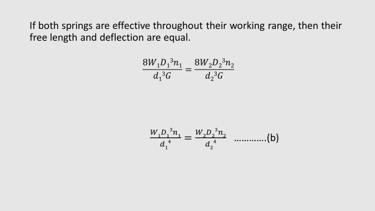
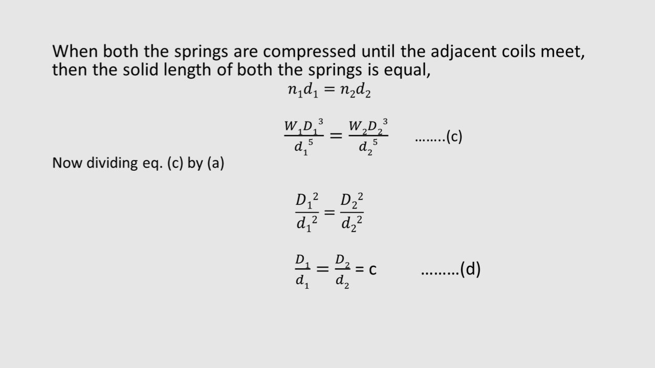
CONCENTRIC SPRINGS A concentric or composite spring is used for one of the following purposes : 1. To obtain greater spring force within a given space. 2. To insure the operation of a mechanism in the event of failure of one of the springs. The concentric springs for the above two purposes may have two or more springs and have the same free lengths and are compressed equally. Such springs are used in automobile clutches, valve springs in aircraft, heavy duty diesel engines and rail-road car suspension systems. Sometimes concentric springs are used to obtain a spring force which does not increase in a direct relation to the deflection but increases faster. Such springs are made of different lengths as The shorter spring begins to act only after the longer spring is compressed to a certain amount. These springs are used in governors of variable speed engines to take care of the variable centrifugal force.

9
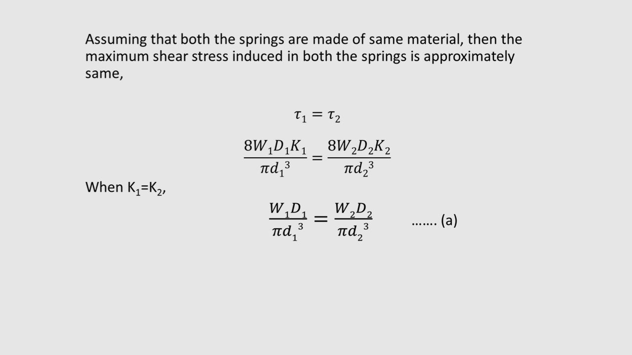
The adjacent coils of the concentric spring are wound in opposite directions to eliminate any tendency to bind. If the same material is used, the concentric springs are designed for the same stress. In order to get the same stress factor (K), it is desirable to have the same spring index (C ). Consider a concentric spring as shown in Fig. (a)
, it is desirable to have the same spring index (C ). Consider a concentric spring as shown in Fig. (a)")
10
Consider a concentric spring as shown in previous slide,
Let, W = Axial load, W1 = Load shared by outer spring, W2 = Load shared by inner spring, d1 = Diameter of spring wire of outer spring, d2 = Diameter of spring wire of inner spring, D1 = Mean diameter of outer spring, D2 = Mean diameter of inner spring, δ1 = Deflection of outer spring, δ2 = Deflection of inner spring, n1 = Number of active turns of outer spring, and n2 = Number of active turns of inner spring.

16
Torsion spring

17
INTRODUCTION It is also a form of helical spring, but it rotates about an axis to create load. It releases the load in an arc around the axis. Mainly used for torque transmission. The ends of the spring are attached to other application objects, so that if the object rotates around the center of the spring, it tends to push the spring to retrieve its normal position.

18
DERIVATION OF FORMULA A little consideration will show that the radius of curvature of the coils changes when the twisting moment is applied to the spring. Thus , the wire is under pure bending. According to A.M.Wahl, the bending stress in a helical torsion spring made of round wire is

19
Cont…

20
Cont…

21
CONFIGURATION Torsion springs are designed and wound to be actuated rotationally, and to provide an angular return force. There are many options for leg configuration so the spring can be attached in different ways. Leg specifications to consider for torsion springs include leg angle, equal leg length, and leg end style. Springs that are straight or parallel on the same side are considered to have a 0º leg angle the increasing angle is in the unwinding direction. Leg end style choices include straight torsion, straight offset, hinged, short hook ends, and hook ends. Torsion spring ends can be bent, twisted, hooked or looped to suit your project needs. Lee Torsion Stock Springs are offered in a choice of 90 degree, 180 degree, 270 degree and 360 degree free leg position.

22
PARAMETERS Dimensions: Inner Diameter, Outer Diameter, Wire Diameter, and Spring Length. The Inner Diameter is specified when the spring is required to slip over a mandrel with sufficient clearance to operate freely. The Outer Diameter is specified when the spring is required to fit into a circular hole with sufficient exterior clearance to operate freely, or if there are outer housing clearance issues. The Spring Length is the length of the spring coil.

23
APPLICATIONS Some familiar examples of uses are the strong, helical torsion springs that operate clothespins and traditional spring-loaded-bar type mousetraps. Other uses are in the large, coiled torsion springs used to counterbalance the weight of garage doors, and a similar system is used to assist in opening the trunk (boot) cover on some sedans. Small, coiled torsion springs are often used to operate pop-up doors found on small consumer goods like digital cameras and compact disc players.
 cover on some sedans. Small, coiled torsion springs are often used to operate pop-up doors found on small consumer goods like digital cameras and compact disc players.")
24
CONICAL AND VOLUTE SPRINGS
Conical Springs Volute Springs

25
Conical Springs Conical springs are used in special applications where a telescopic spring action is required or a spring with spring stiffness that increases with load is desired. In such springs, as the load increases the number of active coils gradually decreases. The decreasing number of coils results in an increasing spring stiffness.

26
Volute Springs A volute spring is a compression spring in the form of a cone (a volute). Under compression, the coils slide past each other, thus enabling the spring to be compressed to a very short length in comparison to what would be possible with a more conventional helix spring. The shape of the initial spring steel (or other material) is a "V", with the ends of the V at either end of the wound spring (which forms a distorted cylinder, of wider diameter at the center), and the bottom point of the V at the center. Such springs can frequently be found as a component of garden secateurs. Short posts anchored in each side of the handles, and inserted into each narrow end of the spring, retains the spring in position.
. Under compression, the coils slide past each other, thus enabling the spring to be compressed to a very short length in comparison to what would be possible with a more conventional helix spring. The shape of the initial spring steel (or other material) is a V , with the ends of the V at either end of the wound spring (which forms a distorted cylinder, of wider diameter at the center), and the bottom point of the V at the center. Such springs can frequently be found as a component of garden secateurs. Short posts anchored in each side of the handles, and inserted into each narrow end of the spring, retains the spring in position.")
27
A volute spring. Under compression the coils slide over each other, so affording longer travel.

28
APPLICATION Automotive parts Agriculture Consumer product
Energy and utility industry

29
Spiral springs

30
It is made of a band of steel wrapped around itself a number of times to create a geometric shape.
Its inner end is attached to an arbor and outer end is attached to a retaining drum. It has a few rotations and also contains a thicker band of steel. It releases power when it unwinds.

31
When the outer or inner end of this type of spring is wound up in such a way that there is a tendency in the increase of number of spirals of the spring, the strain energy is stored into its spirals. This energy is utilised in any useful way while the spirals open outslowly. Usually the inner end of spring is clamped to an arbor while the outer end may be pinned or clamped. Since the radius of curvature of every spiral decreases when the spring is wound up,therefore the material of the spring is in a state of pure bending.

32
Belleville Spring A Belleville Spring consists of a coned disk.
This type of spring is also called “cone disk spring”. It is invented by ‘Julian Belleville’ and patented iv France in 1867.

33
It has typical load deflection characteristics as per fig.
The variation of (h/t) ratio produce wide variety of curve which are useful in application involving snap acting mechanism. When (h/t) reduced to , the central portion of the curve becomes horizontal , which means load is constant for this range of deflection.
 ratio produce wide variety of curve which are useful in application involving snap acting mechanism. When (h/t) reduced to , the central portion of the curve becomes horizontal , which means load is constant for this range of deflection.")
34
This portion of the curve is useful for engaging and disengaging of the clutch , when it is used as a clutch spring. ADVANTAGES It is simple in construction and easy to manufacture. It is a compact spring unit. It is especially useful where very large force is desired for small deflection of spring. It provides wide range of spring constants making it versatile. It can provide any linear or non-linear load deflection characteristics.

35
The individual coned disks of a particular size and thickness can be stacked in series , parallel or series-parallel combinations. These combination s provides wide variety of spring constants without changing the design. such like, When they are in series , double deflection is obtained for same load. When they are in parallel , almost double force is obtain for a given deflection.

36
APPLICATION They are used in, Plate Clutches Brakes
Gun recoil mechanisms Relief valves Wide varieties of bolted connections.

37
THANK YOU

Similar presentations


, which transmits power and rotational motion. Machine.>")


 that can be twisted, pulled, or stretched by some force. They can return to their original.>")
 is a tool or instrument.>")

 Springs: Helical and leaf springs – Springs in series and parallel.>")