Download presentation
Presentation is loading. Please wait.

1
MUZAIDI BIN OTHMAN @ MARZUKI muzaidi@unimap.edu.my PPKSE

2
Single phase system, three phase voltage generation, phasor diagram Line & Phase Quantitites: Phase voltages, Line voltages, Phase currents, Line currents, balanced load Three phase connection: Wye and Delta, phase sequence, balanced load, Wye–Wye Connection, Wye – Delta connection, Delta – Delta connection, Delta – Wye connection

3
Explain and describe the single phase system, three phase voltage generation and the phasor diagram Explain line and phase quantities. Explain and analyze three phase connection in balanced load: Wye and Delta Calculate the phase and line voltages and currents Calculate the active and reactive power

4
AC generator is designed to develop a single sinusoidal voltage for each rotation of shaft is referred to single phase AC generator. If number coil of conductor increased in specific manner, the result is a poly phase AC generator, which develop more than one AC phase voltage per rotation of the motor.

5
3 phase system are preferred over single phase system for the transmission of power: - Thinner conductor can be used to transmit power at same voltage, which reduce amount of copper and in turn reduces maintenance and construction cost. - The lighter line easy to install and supporting structures. - 3 phase equipment and motors have preferred starting and running characteristics because more power can be delivered compared single phase. - Most larger motor in 3 phase (self starting and not required special design or additional starting circuit)
.")
6
The frequency generated is determined by the number of poles on the rotor (generator) and the speed which the shaft is turned. United Stated = 60 Hz Europe (including Malaysia) = 50 Hz The number of phase voltage that can be produced by a polyphase generator is not limited to the three. Any number of phase can be obtained by spacing the windings for each phase at the proper angular position around the stator.
 = 50 Hz The number of phase voltage that can be produced by a polyphase generator is not limited to the three. Any number of phase can be obtained by spacing the windings for each phase at the proper angular position around the stator..")
7
The three phase generator has three induction coils placed 120 apart on the stator. Three coils have an equal number of turns and each coil rotates with the same angular velocity, the voltage induced across each coil will have the same peak value, shape and frequency.

8
At any instant of time, the algebraic sum of the three phase voltages of three phase generator is zero.

9
The sinusoidal expression for each of the induced voltage Phase expression (in polar form):
:")
10
Demonstrating that the vector sum of the phase voltages of a three- phase generator is zero. Phasor diagram for the phase voltages of a three-phase generator.

11
A 3 phase system is equivalent to the 3 single phase system. There is 2 type of 3 phase connection system: - star/wye (Y) connection - delta (Δ) connection. Star/wye Y) connection Delta connection -Connection for generator
 connection - delta (Δ) connection. Star/wye Y) connection Delta connection -Connection for generator.")
12
Connection for load: Y connection Delta connection

13
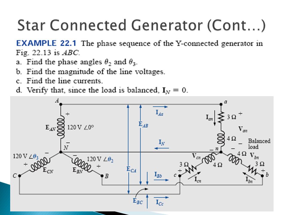
If the 3 terminals denoted N are connected together, the generator is referred to as a Y-connected 3 phase generator. Phase voltage (phase to neutral): E AN, E BN, E CN Line voltage (Line to Line): E AB, E BC, E CA
: E AN, E BN, E CN Line voltage (Line to Line): E AB, E BC, E CA.")
14
Neutral point : The point at which all terminals are connected. 2 type Y-connected generator: - Y-connected, 3 phase, 3 wire generator (if wire neutral not connected to the load) - Y-connection, 3 phase, 4 wire generator (if wire neutral connected to the load) The 3 conductors connected to the load is called lines.
 - Y-connection, 3 phase, 4 wire generator (if wire neutral connected to the load) The 3 conductors connected to the load is called lines..")
15
The phase sequence can be determined by the order in which the phasors representing the phase voltages pass through a fixed point on the phasor diagram if the phasors are rotated in a counterclockwise direction. Determining the phase sequence from the phase voltages of a three-phase generator.

16
Drawing the phasor diagram from the phase sequence ABC for line voltage E CN E AN E BN Drawing the phasor diagram from the phase sequence ABC for phase voltage

17
Drawing the phasor diagram from the phase sequence ACB for line Voltage Drawing the phasor diagram from the phase sequence ACB for phaseVoltage

18
Relation between Phase voltage & line voltage in phasor diagram

19
(a) Phasor diagram of the line and phase voltages of a three-phase generator; Determining a line voltage E AB
 Phasor diagram of the line and phase voltages of a three-phase generator; Determining a line voltage E AB")
20
If the phase voltage E AN is taken as the reference: If the line voltage E AB is taken as the reference:

21
Applying KVL, line voltage for the generator is (for ABC sequence):
:")
22
Find E AB E BC E CA if E AN : (a) (b)
 (b)")
23
Y-connected generator with a Y-connected load - symbolic as Y-Y

24
Y-connected generator with a Y-connected load (cont…) - If load is balanced, the neutral connection can be removed without affecting the circuit in any manner: then,
 - If load is balanced, the neutral connection can be removed without affecting the circuit in any manner: then,")
25
Y-connected generator with a Y-connected load(cont…)
")
27
Example: - Calculated the line current in each phase in the 3 wire, Y-Y system as shown below:

28
Y-connected generator with a Δ-connected load - symbolic as Y- Δ

29
- For balanced load in Y- Δ system, voltage across each phase of load is equal to the line voltage of generator: -Balanced load mean: For the balanced load, the line currents will be equal in magnitude as will the phase current.

30
Y-connected generator with a Δ-connected load (cont..)
")
32
Example: - A balanced positive sequence Y-connected source with E AN = 100 0 V is connected to a Δ-connected balanced load (8+j4) Ω per phase. Calculated magnitude of line current.

33
If we rearranged the coils of the generator as shown below, the system is referred to as a three phase, three wire, Δ-connected AC generator.

34
In generator connection, the phase and line voltages are equivalent and equal to the voltage induced across each coil of the generator.

35
Generator: Phase current: I AC, V BA, V CB Line current: I Aa, I Bb, I Cc

36
Generator: If the phase current I BA is taken as the reference:

37
Generator: If the line voltage E AB is taken as the reference:

38
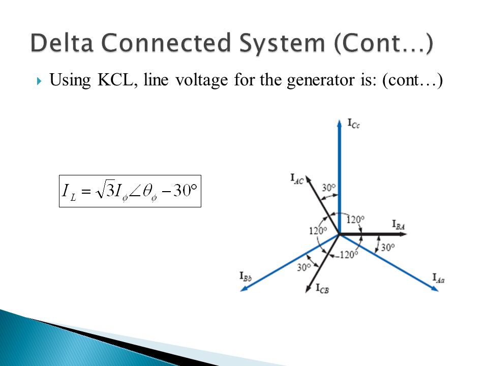
Using KCL, line current for the generator is:

39
Using KCL, line voltage for the generator is: (cont…)
")
41
For Δ-connection, the line voltage are equal to phase voltage.

42
Load: Phase current: I ab, I bc, I ca Line current: I Aa, I Bb, I cc Phase Voltage: V ab, V bc, V ca Line Voltage: V Aa, V Bb, V Cc

43
Load: If the phase current I ab is taken as the reference:

44
Using KCL, line current for the load is:

45
Using KCL, line voltage for the load is: (cont…)
")
46
Δ-connected generator with a Δ-connected load - symbolic as Δ-Δ

48
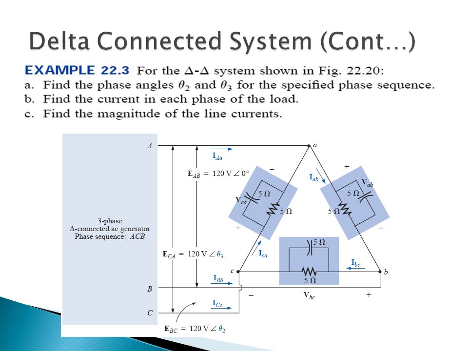
Example - A balanced delta connected load having an impedance 20-j15 Ω is connected to a delta connected, positive sequence generator having V AB = 330 0 V. Calculate the phase currents of the load and the line currents.

49
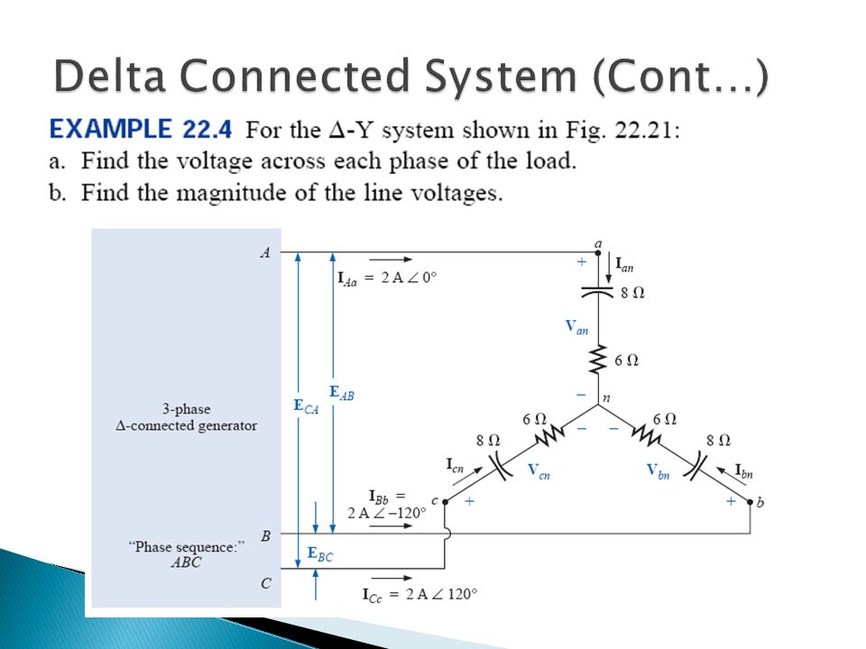
Δ-connected generator with a Y-connected load - symbolic as Δ-Y

51
Example - A balanced Y-connected load with a phase impedance 40-j25 Ω is supplied by a balanced, positive sequence delta-connected source with a line voltage of 210 V. Calculate the phase currents. Use V AB as reference.

Similar presentations


 = V m sin t i v1v1 Load AC generator v2v2 2.>")


 Three Phase System.>")

