Download presentation
Presentation is loading. Please wait.

1
AC Motors AC current reverses direction Two parts: stator and rotor
Stator: stationary electrical component Rotor: rotates the motor shaft Two types Synchronous motor Induction motor Alternating current (AC) motors use an electrical current, which reverses its direction at regular intervals. An AC motor has two basic electrical parts: a "stator" and a "rotor". The stator is in the stationary electrical component. The rotor is the rotating electrical component, which in turn rotates the motor shaft. The main advantage of DC motors over AC motors is that speed is more difficult to control for AC motors. To compensate for this, AC motors can be equipped with variable frequency drives but the improved speed control comes together with a reduced power quality. There are two types of AC motors: synchronous (see figure) and induction. The main difference between the synchronous motor and the induction motor is that the rotor of the synchronous motor travels at the same speed as the rotating magnetic field.
 motors use an electrical current, which reverses its direction at regular intervals. An AC motor has two basic electrical parts: a stator and a rotor . The stator is in the stationary electrical component. The rotor is the rotating electrical component, which in turn rotates the motor shaft. The main advantage of DC motors over AC motors is that speed is more difficult to control for AC motors. To compensate for this, AC motors can be equipped with variable frequency drives but the improved speed control comes together with a reduced power quality. There are two types of AC motors: synchronous (see figure) and induction. The main difference between the synchronous motor and the induction motor is that the rotor of the synchronous motor travels at the same speed as the rotating magnetic field.")
2
AC Motors Alternating current (AC) motors use an electrical current, which reverses its direction at regular intervals. An AC motor has two basic electrical parts: a "stator" and a "rotor". The stator is in the stationary electrical component. The rotor is the rotating electrical component, which in turn rotates the motor shaft. The main advantage of DC motors over AC motors is that speed is more difficult to control for AC motors. To compensate for this, AC motors can be equipped with variable frequency drives but the improved speed control comes together with a reduced power quality. There are two types of AC motors: synchronous (see figure) and induction. The main difference between the synchronous motor and the induction motor is that the rotor of the synchronous motor travels at the same speed as the rotating magnetic field.
 and induction. The main difference between the synchronous motor and the induction motor is that the rotor of the synchronous motor travels at the same speed as the rotating magnetic field.")
5
AC – Induction motor Most common motors in industry Advantages:
Simple design Inexpensive High power to weight ratio Easy to maintain Direct connection to AC power source Induction motors are the most common motors used for various equipments in industry. Their popularity is due to their simple design, they are inexpensive (half or less of the cost of a DC motor) High power to weight ratio (about twice that of a DC motor) easy to maintain can be directly connected to an AC power source
 High power to weight ratio (about twice that of a DC motor) easy to maintain. can be directly connected to an AC power source.")
6
AC – Induction motor How induction motors work
Electricity supplied to stator Magnetic field generated that moves around rotor Current induced in rotor Electromagnetics Stator Rotor Rotor produces second magnetic field that opposes stator magnetic field Rotor begins to rotate Induction motors work as follows: Electricity is supplied to the stator, which generates a magnetic field. This magnetic field moves at synchronous speed around the rotor, which in turn induces a current in the rotor. The rotor current produces a second magnetic field, which tries to oppose the stator magnetic field, and this causes the rotor to rotate.

7
AC – Induction motor Single-phase induction motor One stator winding
Single-phase power supply Squirrel cage rotor Require device to start motor Up to 3 to 4 HP Household appliances: fans, washing machines, dryers Induction motors can be classified into two main groups: single-phase and three-phase induction motors Single-phase induction motors. These only have one stator winding, operate with a single-phase power supply, have a squirrel cage rotor, and require a device to get the motor started. This is by far the most common type of motor used in household appliances, such as fans, washing machines and clothes dryers, and for applications for up to 3 to 4 horsepower.

8
Shaded-pole motor The shaded pole delays the creation of the magnetic field in that portion of the stator poles. This produces a magnetic field in the shaded portion that is approximately 90° apart from the magnetic field produced in the main portion of the pole. Considered a nonreversible motor.

9
Split-phase motor Start winding
Many turns of heavy-gauge wire Centrifugal switch opens after start-up removing the start winding from the circuit. Reverse direction of rotation by interchanging run winding or start winding connections (preferred).
.")
10
Three Types of Capacitor Start Motors
Capacitor Start (disconnects capacitor after motor speed picks up) Capacitor Run (Keeps the capacitor connected during the operation of the motor, in order to keep the electric power consumption low) Capacitor Start-Run (uses two capacitors, one for starting and one for running. This further improves Power Consumption)
 Capacitor Run (Keeps the capacitor connected during the operation of the motor, in order to keep the electric power consumption low) Capacitor Start-Run (uses two capacitors, one for starting and one for running. This further improves Power Consumption)")
11
Capacitor-start motor
Start circuit has: Centrifugal switch Start winding Start capacitor This produces higher starting torque. Run winding Reverse direction of rotation by interchanging run winding or start winding connections (preferred).
.")
12
Capacitor-run motor The capacitor shifts the phase on one of the windings so that the voltage across the winding is at 90° from the other winding Run capacitor produces higher running torque. Start winding stays as part of the circuit Run winding Reverse direction of rotation by interchanging run winding or start winding connections (preferred).
.")
13
Capacitor-start/capacitor-run motor
Start circuit: Start winding Centrifugal switch Start capacitor Larger value produces higher starting torque. Run winding Run capacitor Smaller value produces higher running torque. Reverse direction of rotation by interchanging run winding or start winding connections (preferred).
.")
14
Capacitor start-run reverse connections

15
What are Poles in a Motor?
Winding(s) which produce the magnetic field(s) necessary to cause the rotor to turn. 3 Phase; 2 Pole Motor
 which produce the magnetic field(s) necessary to cause the rotor to turn. 3 Phase; 2 Pole Motor.")
16
Requires DC voltage for starting excitation Has low starting torque
AC - Synchronous motor Requires DC voltage for starting excitation Has low starting torque Suited for low load applications Rotor of the synchronous motor travels at the same speed as the rotating magnetic field A synchronous motor is an AC motor, which runs at constant speed fixed by frequency of the system. It requires direct current (DC) for excitation and has low starting torque, and synchronous motors are therefore suited for applications that start with a low load, such as air compressors, frequency changes and motor generators. Synchronous motors are able to improve the power factor of a system, which is why they are often used in systems that use a lot of electricity. This motor rotates at a synchronous speed, which is given by the following equation Ns = 120 f / P Where: f = frequency of the supply frequency P= number of poles
 for excitation and has low starting torque, and synchronous motors are therefore suited for applications that start with a low load, such as air compressors, frequency changes and motor generators. Synchronous motors are able to improve the power factor of a system, which is why they are often used in systems that use a lot of electricity. This motor rotates at a synchronous speed, which is given by the following equation. Ns = 120 f / P. Where: f = frequency of the supply frequency. P= number of poles.")
17
Synchronous motor Three-Phase Motors
Parts Rotor with single winding Slip rings and brushes Three-phase stator windings

18
AC - Synchronous motor Constant speed fixed by system frequency
Used where there is a need to improve the power factor Synchronous speed (Ns): F = frequency of the voltage source supplied P = number of poles A synchronous motor is an AC motor, which runs at constant speed fixed by frequency of the system. It requires direct current (DC) for excitation and has low starting torque, and synchronous motors are therefore suited for applications that start with a low load, such as air compressors, frequency changes and motor generators. Synchronous motors are able to improve the power factor of a system, which is why they are often used in systems that use a lot of electricity. This motor rotates at a synchronous speed, which is given by the following equation Ns = 120 f / P Where: f = frequency of the supply frequency P= number of poles
: F = frequency of the voltage source supplied. P = number of poles. A synchronous motor is an AC motor, which runs at constant speed fixed by frequency of the system. It requires direct current (DC) for excitation and has low starting torque, and synchronous motors are therefore suited for applications that start with a low load, such as air compressors, frequency changes and motor generators. Synchronous motors are able to improve the power factor of a system, which is why they are often used in systems that use a lot of electricity. This motor rotates at a synchronous speed, which is given by the following equation. Ns = 120 f / P. Where: f = frequency of the supply frequency. P= number of poles.")
19
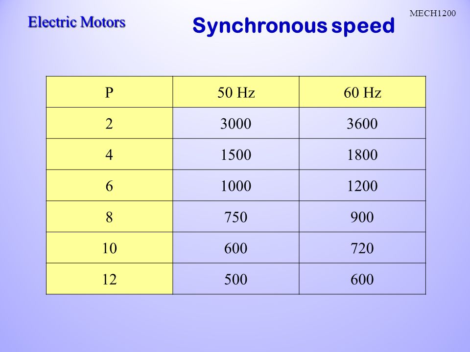
Synchronous speed P 50 Hz 60 Hz 2 3000 3600 4 1500 1800 6 1000 1200 8
750 900 10 600 720 12 500
20
Each AC phase has 4 stator windings
4-Pole stator winding Each AC phase has 4 stator windings Each winding is in opposite direction from preceding winding, making a N-S-N-S field Field strength rotates with AC current of each phase Arrow in stator depicts magnetic field of windings according to the left hand rule. X is out of plane; dot is into plane.

21
AC – Induction motor Three-phase induction motor
Three-phase supply produces magnetic field Squirrel cage or wound rotor Self-starting High power capabilities Fractional to 100’s of HP Applications: pumps, compressors, conveyor belts, grinders 70% of motors in industry! Induction motors can be classified into two main groups: Single-phase induction motors. These only have one stator winding, operate with a single-phase power supply, have a squirrel cage rotor, and require a device to get the motor started. This is by far the most common type of motor used in household appliances, such as fans, washing machines and clothes dryers, and for applications for up to 3 to 4 horsepower. Three-phase induction motors. The rotating magnetic field is produced by the balanced three-phase supply. These motors have high power capabilities, can have squirrel cage or wound rotors (although 90% have a squirrel cage rotor), and are self-starting. It is estimated that about 70% of motors in industry are of this type, are used in, for example, pumps, compressors, conveyor belts, heavy-duty electrical networks, and grinders. They are available in 1/3 to hundreds of horsepower ratings.
, and are self-starting. It is estimated that about 70% of motors in industry are of this type, are used in, for example, pumps, compressors, conveyor belts, heavy-duty electrical networks, and grinders. They are available in 1/3 to hundreds of horsepower ratings.")
22
Aka: Asynchronous motor
AC – Induction motor Aka: Asynchronous motor The induction ac motor is a common form of an asynchronous motor Is basically an AC transformer with a rotating secondary

23
AC – Induction motor Components Rotor
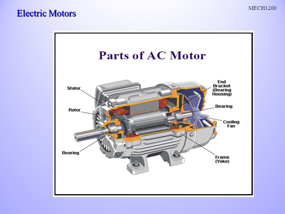
Squirrel cage: conducting bars in parallel slots Wound rotor: 3-phase, double-layer, distributed winding An induction motor has two main electrical components as shown in the figure Rotor. Induction motors use two types of rotors: A squirrel-cage rotor consists of thick conducting bars embedded in parallel slots. These bars are short-circuited at both ends by means of short-circuiting rings. A wound rotor has a three-phase, double-layer, distributed winding. It is wound for as many poles as the stator. The three phases are wired internally and the other ends are connected to slip-rings mounted on a shaft with brushes resting on them. Stator. The stator is made up of a number of stampings with slots to carry three-phase windings. It is wound for a definite number of poles. The windings are geometrically spaced 120 degrees apart Stator Stampings with slots to carry 3-phase windings Wound for definite number of poles

24
3-phase Induction Motor Operation
Arrows shows stator magnetic field vector Stator field precedes the rotor’s induction field From wikipedia: WARNING Animation shows flaws when GIF is resized. The reason for this behavior is unclear, but it is common both to Mozilla and Konqueror on Linux. Any advice welcome Note: IE 7.0 does not seem to share this deficiency. (The error seems to affect Chrome on Windows XP too) Model of 3 phase synchronous electric motor with animated vector adding of stator coil magnetic fields. Stator phases R, S and T have sine current shifted by 120 degrees between each. Magnetic field is proportional to current in linear approximation. Magnetic field vectors of the phases add up on the axis of the motor as vectors, combining into single rotating vector according to parallelogram law, which is clearly visible. Rotor has a constant current and hence constant magnetic field, which shows the inclination to follow rotating magnetic field of the stator coils, causing rotor to rotate. This particular image shows phase vectors change in time, the other one sums them using parallelogram theorem.
 Model of 3 phase synchronous electric motor with animated vector adding of stator coil magnetic fields. Stator phases R, S and T have sine current shifted by 120 degrees between each. Magnetic field is proportional to current in linear approximation. Magnetic field vectors of the phases add up on the axis of the motor as vectors, combining into single rotating vector according to parallelogram law, which is clearly visible. Rotor has a constant current and hence constant magnetic field, which shows the inclination to follow rotating magnetic field of the stator coils, causing rotor to rotate. This particular image shows phase vectors change in time, the other one sums them using parallelogram theorem.")
25
Reversing Direction of a 3 Phase Motor
Interchange any two of the three stator leads. The industry standard is to switch T1 and T3 . The wound-rotor induction motor is considered to be a variable-speed motor. Initial cost is higher and maintenance costs are higher than for a squirrel-cage induction motor.

26
Reversing Direction of a 3 Phase Motor
B C

27
Changing AC Motor Speed
Voltage – Hertz Ratio: Operating motor in a range different from rated frequency and voltage affects both torque and current .

28
Changing AC Motor Speed
Voltage – Hertz Ratio: Maintaining the ratio gives a constant torque range For a synchronous motor rated for 3 phase, 460 volts, 60 Hz and 3600 rpm, what will be the operating frequency and voltage if the motor controller commands the motor to run at 2750 rpm? 7.67 2 poles 45.83 Hz volts

29
Squirrel-cage induction motor
Parts: Rotor Stator The squirrel-cage induction motor is considered to be a fixed-speed motor.

30
Motor never runs at synchronous speed but lower actual rotor speed
AC – Induction motor Speed and slip Motor never runs at synchronous speed but lower actual rotor speed Difference is “slip” Install slip ring to avoid this Calculate % slip: In practice however, the motor never runs at synchronous speed but at a lower “base speed”. The difference between these two speeds is the “slip”, which increases with higher loads. Slip only occurs in all induction motors. To avoid slip, a slip ring can be installed, and these motors are called “slip ring motors”. The following equation can be used to calculate the percentage slip % Slip = Ns – Nb x 100 Ns Where: Ns = synchronous speed in RPM Nb = base speed in RPM Ns = synchronous speed in RPM NR = rotor speed in RPM

31
Wound-rotor induction motor
The rotor contains windings. Slip rings and brushes provide an electrical connection to the rotor windings. The wound-rotor induction motor is considered to be a variable-speed motor. Initial cost is higher and maintenance costs are higher than for a squirrel-cage induction motor.

32
Relationship: load, speed and torque
“Breakdown” torque: 75% speed and highest torque = ft-#’S “Pull-up” torque: lower torque and increasing speed Starting Torque (aka LRT): high torque and low speed The figure shows the typical torque-speed curve of a three-phase AC induction motor with a fixed current. When the motor: (Click once) Starts there is a high starting current and low torque (“pull-up torque”). (Click once) Reaches 80% of the full speed, the torque is at its highest level (“pull-out torque”) and the current begins to drop. (Click once) Is at full speed, or synchronous speed, the torque and stator current drop to zero. Full load torque: motor operates at rated voltage, frequency and load and stator current are zero 30 HP 1765 RPM
: high torque and low speed. The figure shows the typical torque-speed curve of a three-phase AC induction motor with a fixed current. When the motor: (Click once) Starts there is a high starting current and low torque ( pull-up torque ). (Click once) Reaches 80% of the full speed, the torque is at its highest level ( pull-out torque ) and the current begins to drop. (Click once) Is at full speed, or synchronous speed, the torque and stator current drop to zero. Full load torque: motor operates at rated voltage, frequency and load and stator current are zero. 30 HP RPM.")
33
Torque Curve Calculate: Speed at 100% full load current % Slip

34
AC Motor Data Plate

35
Types of Motor Enclosures
ODP – Open Drip Proof TENV – Totally Enclosed Non-Ventilating TEFC – Totally enclosed Fan Cooled XP – Explosion Proof

36
Types of Motor Enclosures
ODP – Open Drip Proof Air flows through motor (fan blades help flow) Used in environments free from contaminants
 Used in environments free from contaminants.")
37
Types of Motor Enclosures
TENV – Totally Enclosed Non-Ventilating Protect motor from corrosive and harmful elements Frame fins help to dissipate heat

38
Types of Motor Enclosures
TEFC – Totally enclosed Fan Cooled Similar to TENV except has external fan for cooling

39
Types of Motor Enclosures
XP – Explosion Proof Similar to TEFC but enclosures are cast iron

40
Hazardous Locations Division I – Hazardous material present in the air as a norm Division II - Hazardous material present in the air as an abnormal event

41
AC single phase motors are:
Summary DC motors are: permanent magnet series-wound, shunt-wound, compound-wound AC single phase motors are: the shaded-pole, split-phase, capacitor-start, capacitor-run, capacitor-start/ capacitor-run

42
Name two motors that do not need brushes for their rotor windings.
Questions Name two motors that do not need brushes for their rotor windings. Which motor supplies the highest output torque to weight ratio? Why is it not recommended to use dc motors in artificial hearts? In an environment that contains explosive gases, such as in mines, which motor do you recommend using: a) series dc motor b) shunt dc motor c) induction motor d) universal motor More questions: How does the rotor of a dc motor maintain electrical contact with its commutation circuit? Name two motors that do not need brushes for their rotor windings.
 series dc motor b) shunt dc motor. c) induction motor d) universal motor. More questions: How does the rotor of a dc motor maintain electrical contact with its commutation circuit Name two motors that do not need brushes for their rotor windings.")
Similar presentations


>")


 M.Tech 1 st Year Textile Engineering.>")


