Download presentation
Presentation is loading. Please wait.

2
MEH108 - Intro. To Engineering Applications KOU Electronics and Communications Engineering

3
Introduction LabVIEW - Laboratory Virtual Instrument Engineering Workbench Product of National Instruments (ni.com)!
!")
4
Learn LabVIEW : Web Courses http://www.ni.com/f/students/12/7052/en/ 1. LabVIEW Environment Learn how to navigate LabVIEW and use the block diagram, front panel, and Functions and Controls palettes. Then explore how to use graphs and charts and build a user interface. 2. Loops and Execution Structures See how to loop code and conditionally execute code in LabVIEW using For Loops, While Loops, and Case structures. 3. Data Types and Structures Explore the different data types and methods to organize and group data, controls, and indicators in LabVIEW. 4. Graphical Programming Examine the basics of graphical programming and methods to determine data flow and order of execution in the LabVIEW environment. 5. Programming Tools Discover how to use important tools in LabVIEW that can save you time.

5
Why do we use LabVIEW? Allowing “easy” automated data acquisition, instrument control, and industrial automation! Allow people with limited coding experience to write programs develop automated experiments much faster than with conventional programming environments! Another key benefit of LabVIEW over conventional programming environments is the extensive support for accessing instrumentation hardware Writing instrument drivers by hand requires a hardware and operating system expert along with thousands of lines of code

6
LabVIEW Basics LabVIEW relies on graphical symbols rather than textual language to describe programming actions LabVIEW programs are called Virtual Instruments (VIs)! This is because their appearance (like a circuit schematic) and operation imitate actual instruments/circuit blocks! Execution of a program is based on the principle of dataflow, in which functions execute only after receiving the necessary data!
 and operation imitate actual instruments/circuit blocks. Execution of a program is based on the principle of dataflow, in which functions execute only after receiving the necessary data!.")
8
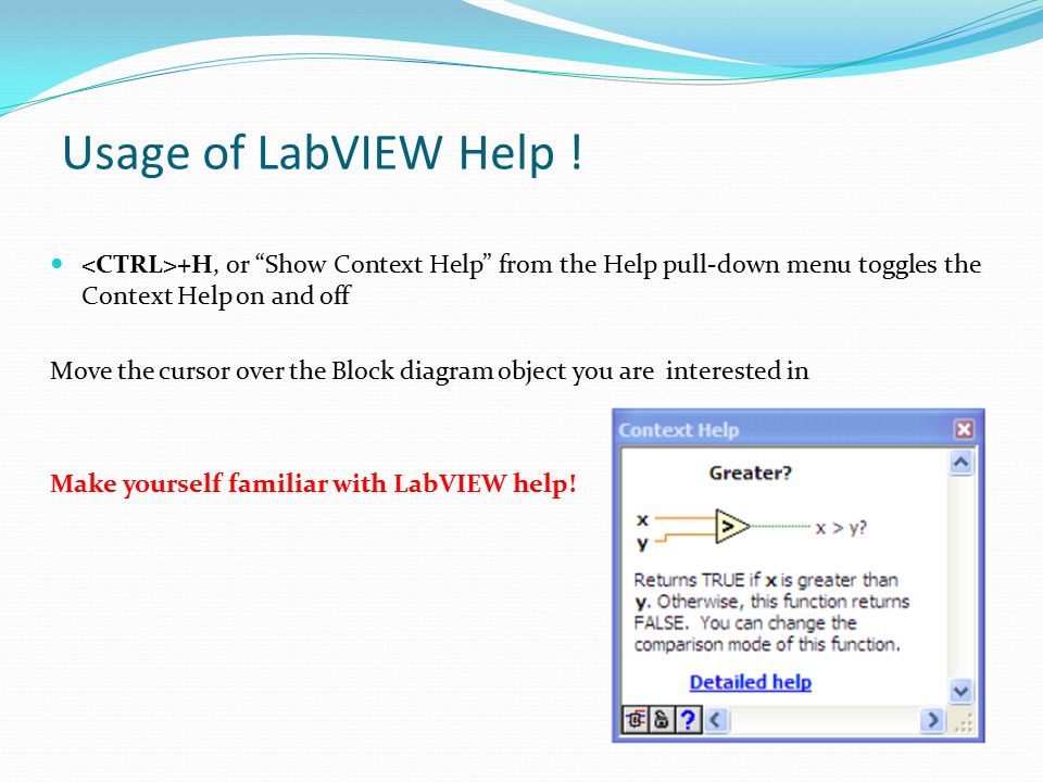
Usage of LabVIEW Help ! +H, or “Show Context Help” from the Help pull-down menu toggles the Context Help on and off Move the cursor over the Block diagram object you are interested in Make yourself familiar with LabVIEW help!

9
Front Panel Controls = Inputs Indicators = Outputs Block Diagram Accompanying “program” for front panel Components “wired” together LabVIEW Programs Are Called Virtual Instruments (VIs)
")
10
LabVIEW Front Panel All user interface goes here! Used to display Controls or Indicators Highly customizable

11
Control? or Indicator? Controls = Inputs from the user = Source Terminals Indicators = Outputs to the user = Destinations

12
LabVIEW Block Diagram Actual program Invisible to user Read left to right, like a book Where the MAGIC happens!

13
Terminals When you place a control (or indicator) on the FRONT PANEL LabVIEW automatically creates a corresponding control (or indicator) terminal on the BLOCK DIAGRAM
 on the FRONT PANEL LabVIEW automatically creates a corresponding control (or indicator) terminal on the BLOCK DIAGRAM")
14
Manipulating Controls and Indicators Right click on an indicator to Change to control Change format or precision Right click on a control to Change to indicator Change mechanical action (whether to latch open or closed, and what to use as default…)
")
15
Wiring Connections Wires transport data through the block diagram Wire color indicates variable type A red “X” means something is wrong!

16
Wires A LabVIEW VI is held together by wires connecting nodes and terminals; they deliver data from one source terminal to one or more destination terminals.

17
Broken wires If you connect more than one source or no source at all to a wire, LabVIEW DISAGREES with what you’re doing, and the wire will appear broken

18
Messy vs. Clean Wiring CLEAN: Easy to troubleshoot MESSY: What is going on?

19
Basic wires used in block diagrams and corresponding types Each wire has different style or color, depending on the data type that flows through the wire: Scalar1D array2D arrayColor Floating-point number orange Integer numberblue Booleangreen Stringpink

20
Running LabVIEW Programs ALMOST ALWAYS put your program in some sort of loop that can be stopped with a control AVOID using the red “x” to stop your program

21
Insert a digital indicator or control Insert a boolean control (button or switch)
")
22
Add a structure such as for, while, and case statements Add a numeric operator (+,-,…) File I/O Add a boolean operator (and, or…) Data Acquisition Signal analysis Comparison Mathematical Functions Timing/dialog
 File I/O Add a boolean operator (and, or…) Data Acquisition Signal analysis Comparison Mathematical Functions Timing/dialog")
25
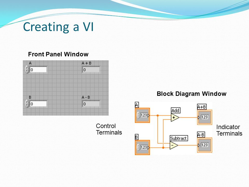
Control Terminals Block Diagram Window Front Panel Window Indicator Terminals Creating a VI

26
Example 1: Craps From the functions – numeric panel insert a pair of dice From the Controls panel insert a numeric digital indicator (on the front panel) Use the wiring tool to connect the two (in the wiring diagram) and click the “run” button repeatedly. Numbers from 0.00 to 1.00 should be displayed in the front panel

27
Example 1: Craps (continued) Delete the wire Add a multiplication node and a numeric constant to allow multiplication by 5 Add an addition node and numeric constant to allow addition of 1 Add a mathematical “Round to Nearest” node. Make a second copy of this structure to represent a second die and wire them together through an addition node with an output to a numeric constant This wiring diagram simulates the rolling of 2 dice and their addition to form a number from 2 through 12.

28
Section II – Elements of Typical Programs A. Loops While Loop For Loop B. Functions and SubVIs Types of Functions Creating Custom Functions (SubVI) Functions Palette & Searching C. Decision Making and File IO Case Structure Select (simple If statement) File I/O
 Functions Palette & Searching C. Decision Making and File IO Case Structure Select (simple If statement) File I/O.")
29
Loops While Loops i terminal counts iteration Always runs at least once Runs until stop condition is met For Loops –i terminal counts iterations –Run according to input N of count terminal While Loop For Loop

30
Drawing a Loop 1. Select the structure 2. Enclose code to be repeated 3. Drop or drag additional nodes and then wire

31
What Types of Functions are Available? Input and Output Signal and Data Simulation Acquire and Generate Real Signals with DAQ Instrument I/O Assistant (Serial & GPIB) Analysis Signal Processing Statistics Advanced Math and Formulas Continuous Time Solver Storage File I/O Express Functions Palette
 Analysis Signal Processing Statistics Advanced Math and Formulas Continuous Time Solver Storage File I/O Express Functions Palette.")
32
Create SubVI Enclose area to be converted into a subVI. Select Edit»Create SubVI from the Edit Menu.

33
LabVIEW Functions and SubVIs operate like Functions in other languages Function Pseudo Code function average (in1, in2, out) { out = (in1 + in2)/2.0; } SubVI Block Diagram Calling Program Pseudo Code main { average (in1, in2, pointavg) } Calling VI Block Diagram
 { out = (in1 + in2)/2.0; } SubVI Block Diagram Calling Program Pseudo Code main { average (in1, in2, pointavg) } Calling VI Block Diagram")
34
How Do I Make Decisions in LabVIEW? 1. Case Structures 2. Select (a)(b) (c)
(b) (c)")
35
Loops can accumulate arrays at their boundaries with auto- indexing For Loops auto-index by default While Loops output only the final value by default Right-click tunnel and enable/disable auto-indexing Building Arrays with Loops (Auto-Indexing) Wire becomes thicker Wire remains the same size Auto-Indexing Disabled Auto-Indexing Enabled Only one value (last iteration) is passed out of the loop 1D Array 0 1 2 3 4 5 5
 Wire becomes thicker Wire remains the same size Auto-Indexing Disabled Auto-Indexing Enabled Only one value (last iteration) is passed out of the loop 1D Array")
36
Shift Register – Access Previous Loop Data Available at left or right border of loop structures Right-click the border and select Add Shift Register Right terminal stores data on completion of iteration Left terminal provides stored data at beginning of next iteration Before Loop Begins First Iteration Second Iteration Last Iteration Value 3 Initial Value

Similar presentations


>")


