Download presentation
Presentation is loading. Please wait.

1
A Course In the Design of ABS Piping Our Objectives Presented by Geoffrey D Stone FIMechE C.Eng Provide an insight into what piping designers need & expect Define the role of the supplier & designer Learn some fundamentals of piping design Discover failure analysis techniques Share experiences of problems

2
A Course In the Design of ABS Piping What We Shall Look at This Week
ABS Material Properties Thermoplastic Pipe Design Waterhammer Analysis Typical Applications of ABS Pressure Pipe Some Anticipated Events

3
Stages of the Design Process
Representation-Drawings & Specification Calculation-Engineering & Assumptions Visualisation-Presentation of Information Validation-Testing & Commissioning The stages of design are the responsibility of the designer. The designer will possibly require support from the ABS engineering team.

4
Role of the ABS Pipe Supplier
What the Customer Expects Material Properties Design Criteria Design Guidance Material take off (MTO) Applicable Standards Final Inspection Your company to take the design risk!!! Avoid the following: Accept design risk for a sale Accept MTO risk What you should do Provide only accurate information Take photographs or records on site visits Insist on client drawings design assistance required Advise that inspections do NOT infer responsibility Material properties are generally provided in the Product Specification Manual. However the customer may be undertaking a more in depth design. In this case other material properties may be requested. Care should be taken in providing this information and it s necessary to understand how the information is to be used. The design criteria are specified in standards and codes in addition to the Product Specification Manual Design guidance can be in the form of some of the design tools provided as part of this workshop. Where specific projects require pipe stress or waterhammer analysis and the designer does not have the necessary resources the designer should be referred to a specialist. Sometimes Tyco employs a consultant to provide assistance to the designer where the project is of sufficient magnitude to be viable to undertake. In some instances the customer may provide drawings and seek a take off. Invariably this is when the system has been designed in steel and as part of the sales effort offers are made to provide an alternative system in ABS. In undertaking the MTO care should be taken that the risk of providing the correct materials in sufficient quantity remains with the contractor. The reason for this is that if there are missing items, the contractor wastes materials or fails to control the product issue then a risk exists for the supplier. A better approach is to provide an MTO with details related to each line so that the contractor can see what materials are needed. Then provide a piece part price for additional materials. Final inspection of an installation is often requested by a customer. In the right framework this gives the ABS supplier an opportunity to view the work and be critical of any poor practices. Generally insufficient time and expertise is applied to such exercises and not every detail is checked. It remains the responsibility of the contractor to ensure that the installation complies with the design t the ABS supplier. An inspection should be undertaken in good faith but devoid of responsibility and risk. Risk is a key element in any construction contracting business. Risk has value, that is why insurance companies thrive. They cover risks. Always be careful to avoid risk taking, in particular design risk. Design goes hand in glove with fabrication, erection, testing, operation and maintenance. If the design does not match these other criteria then it is flawed. An ABS pipe supplier is not in control of these other elements so cannot take the design risk. An example you may consider:- If you provide advice to change a steel pipe design to ABS for a refrigeration facility that stores food. The piping fails because the design is not adequate or not followed. $5million of food is wasted as the storage temperature rises. The profit for the ABS sold will not cover the damages. Has your employer professional indemnity insurance? Most unlikely. Is this a risk that should have been taken ? NO. If you are unsure of technical information ensure it is checked before it is provided. What is the source? Is it the latest? How is the designer going to use it? Always be suspicious if the designer is trying to justify using a lower class of product. There are greater risks when ever a lower class of ABS pipe is used. Whenever you are on site always take a digital camera and make records. Ensure that these are stored in the job file. Share them with your colleagues as they may see something that s untoward. Keep a diary of site visits. Record any comments or conversations. These may be of use later. If the customer has no drawings available then how is the system to be installed and comply with the design. If drawings are offered as part of an MTO or for comment ensure that they are filed correctly. When the job is complete try and get copies of the work as executed drawings. Preferably in electronic format.
 Applicable Standards. Final Inspection. Your company to take the design risk!!! Avoid the following: Accept design risk for a sale. Accept MTO risk. What you should do. Provide only accurate information. Take photographs or records on site visits. Insist on client drawings design assistance required. Advise that inspections do NOT infer responsibility. Material properties are generally provided in the Product Specification Manual. However the customer may be undertaking a more in depth design. In this case other material properties may be requested. Care should be taken in providing this information and it s necessary to understand how the information is to be used. The design criteria are specified in standards and codes in addition to the Product Specification Manual. Design guidance can be in the form of some of the design tools provided as part of this workshop. Where specific projects require pipe stress or waterhammer analysis and the designer does not have the necessary resources the designer should be referred to a specialist. Sometimes Tyco employs a consultant to provide assistance to the designer where the project is of sufficient magnitude to be viable to undertake. In some instances the customer may provide drawings and seek a take off. Invariably this is when the system has been designed in steel and as part of the sales effort offers are made to provide an alternative system in ABS. In undertaking the MTO care should be taken that the risk of providing the correct materials in sufficient quantity remains with the contractor. The reason for this is that if there are missing items, the contractor wastes materials or fails to control the product issue then a risk exists for the supplier. A better approach is to provide an MTO with details related to each line so that the contractor can see what materials are needed. Then provide a piece part price for additional materials. Final inspection of an installation is often requested by a customer. In the right framework this gives the ABS supplier an opportunity to view the work and be critical of any poor practices. Generally insufficient time and expertise is applied to such exercises and not every detail is checked. It remains the responsibility of the contractor to ensure that the installation complies with the design t the ABS supplier. An inspection should be undertaken in good faith but devoid of responsibility and risk. Risk is a key element in any construction contracting business. Risk has value, that is why insurance companies thrive. They cover risks. Always be careful to avoid risk taking, in particular design risk. Design goes hand in glove with fabrication, erection, testing, operation and maintenance. If the design does not match these other criteria then it is flawed. An ABS pipe supplier is not in control of these other elements so cannot take the design risk. An example you may consider:- If you provide advice to change a steel pipe design to ABS for a refrigeration facility that stores food. The piping fails because the design is not adequate or not followed. $5million of food is wasted as the storage temperature rises. The profit for the ABS sold will not cover the damages. Has your employer professional indemnity insurance Most unlikely. Is this a risk that should have been taken NO. If you are unsure of technical information ensure it is checked before it is provided. What is the source Is it the latest How is the designer going to use it Always be suspicious if the designer is trying to justify using a lower class of product. There are greater risks when ever a lower class of ABS pipe is used. Whenever you are on site always take a digital camera and make records. Ensure that these are stored in the job file. Share them with your colleagues as they may see something that s untoward. Keep a diary of site visits. Record any comments or conversations. These may be of use later. If the customer has no drawings available then how is the system to be installed and comply with the design. If drawings are offered as part of an MTO or for comment ensure that they are filed correctly. When the job is complete try and get copies of the work as executed drawings. Preferably in electronic format.")
5
ABS Material Properties
Modulus Hoop stress Ring Bending Strain Creep Stiffness Temperature Variation Design Life Toxicity & Taint Abrasion Resistance Chemical Resistance Ultraviolet Resistance The pages below cover this topic

6
Modulus Strain rate & loading changes modulus values
Resin properties change modulus values Modulus affects wavespeed in surge events Modulus important in buried pipeline design Modulus is needed to determine deflection and buckling from design loads Published as 2200MPa at 20ºC (instantaneous) Value determined by ASTM test Standard dog bone test specimen Fixed strain rate Modulus values at other temperatures and design life are required for design The property of modulus is measured using a standard ASTM test. The property varies with temperature, time, rate of strain and the applied load. Hence the single figure published represents only one value. It does not allow the designer to consider all aspects of the applied load to a piping system. The published value of 2200MPa is at 20ºC and represents a maximum figure for the material. Other data is required to enable the engineer to design a pipe system. This data must come from test undertaken on the specific resin used in pipe and fittings manufacture. Some typical data is provided based upon a resin used in pipe line extrusion. For deflection design the minimum value of modulus at the design life of the pipe system is used. For wavespeed in a surge scenario the maximum instantaneous value of modulus is used in determining the celerity. This is used to determine the pressure transients in the system. For buried pipeline design the modulus used in determining the stress, strain, deflection, combined loading and buckling criteria varies dependent upon the properties of the soil. The above matters are discussed in further detail in the Design section below.
 Value determined by ASTM test. Standard dog bone test specimen. Fixed strain rate. Modulus values at other temperatures and design life are required for design. The property of modulus is measured using a standard ASTM test. The property varies with temperature, time, rate of strain and the applied load. Hence the single figure published represents only one value. It does not allow the designer to consider all aspects of the applied load to a piping system. The published value of 2200MPa is at 20ºC and represents a maximum figure for the material. Other data is required to enable the engineer to design a pipe system. This data must come from test undertaken on the specific resin used in pipe and fittings manufacture. Some typical data is provided based upon a resin used in pipe line extrusion. For deflection design the minimum value of modulus at the design life of the pipe system is used. For wavespeed in a surge scenario the maximum instantaneous value of modulus is used in determining the celerity. This is used to determine the pressure transients in the system. For buried pipeline design the modulus used in determining the stress, strain, deflection, combined loading and buckling criteria varies dependent upon the properties of the soil. The above matters are discussed in further detail in the Design section below.")
7
Determination of Modulus
(a) Example of the modulus of elasticity determined on the initial straight portion of the stress-strain curve and secant modulus and (b) secant modulus for two different plastics that are 85% of the initial tangent modulus. 1% Proportional Limit 85% of Tangent Modulus
 Example of the modulus of elasticity determined on the initial straight portion of the stress-strain curve and secant modulus and (b) secant modulus for two different plastics that are 85% of the initial tangent modulus. 1% Proportional Limit. 85% of Tangent Modulus.")
8
Properties of Materials

9
Hoop Stress Hoop stress is the primary design criteria for thermoplastic pipe materials. It is determined by undertaking a series of burst tests at different stress levels. The data is then statistically determined in accordance with ISO /TR 9080 using a standard extrapolation method. The 97.5% lower confidence limit is then used along with a factor of safety of 1.6 to determine the design class of ABS at that temperature. The hoop stress is dependent upon the resin type, temperature and time. The Minimum Required Strength (MRS) of ABS is 16MPa.
 of ABS is 16MPa.")
10
Ring Bending Strain Importance of Strain Property
Comparison to other materials ABS 1% PE 4.0% PVC-U 1% PVC-O 1.3% Steel & DICL Not relevant GRP 0.2 to 0.6 % Ring-bending stiffness has an influence on the deflection, strain and buckling performance of the pipe when buried in the ground, although this is normally of less significance than the stiffness of the embedment. However, where weak or soft soils exist or where there is a high water table, pipe ring-bending stiffness becomes significant. For thermoplastic pipes (ABS, PVC, OPVC or PE), the allowable strains are relatively high and thus deflection or buckling criteria generally govern. For profile wall pipe however, strain may be the governing criterion, depending on the geometry of the profile wall. Because thermoplastic materials creep, stiffness and modulus of elasticity are dependent on the period of time the load is applied. Long-term values are extrapolated using regression analysis in accordance with ISO 9967. For materials such as steel and ductile iron the property is not considered relevant. This is because the material does not exhibit creep. For GRP pipes, allowable strains are relatively low and strain and strain may be the design criterion. Modulus of elasticity and stiffness values vary with the type, arrangement and relative percentage of the different materials used in the GRP composite. GRP can thus have a wide range of stiffness (thus modulus of elasticity), as reflected in the stiffness classes offered by manufacturers. Because a component of GRP is a thermoset plastic that is subject to creep, stiffness and modulus of elasticity are dependent on the period of time the load is applied. BUCKLING Because external loads lead to pipe wall compression, buried pipes have a tendency not only to become oval, but also to buckle. Unless this tendency to buckle is checked, satisfactory values of the deflections and strains determined in AS/NZS do not of themselves indicate that the design is satisfactory. Control of buckling is handled by ensuring a sufficiently large margin of safety between the full external load, including external hydrostatic loads and negative internal pressures, and the calculated buckling capacity. The adopted buckling equations are— (a) for H equal to or less than 0.5 m or where substantial soil support cannot be guaranteed, Timoshenko’s equation 5.4(4), (see Refs 3 and 4); and (b) for H greater than 0.5 m, AS/NZS uses the continuum principle developed by I. D. Moore, (see Refs 10 and 11), which in the form given in Equation 5.4(5) yields similar factors of safety to those obtained using the more conventional formulae based on Lusher’s equation (Refs 2, 3 and 4) except that the soil stiffness has greater influence and the pipe stiffness less influence on the calculation. Timoshenko’s equation predicts a buckling resistance pressure for a condition of uniform external pressure without allowance for soil support, whereas Moore’s equation is valid only where external soil support is present.
, the allowable strains are relatively high and thus deflection or buckling criteria generally govern. For profile wall pipe however, strain may be the governing criterion, depending on the geometry of the profile wall. Because thermoplastic materials creep, stiffness and modulus of elasticity are dependent on the period of time the load is applied. Long-term values are extrapolated using regression analysis in accordance with ISO For materials such as steel and ductile iron the property is not considered relevant. This is because the material does not exhibit creep. For GRP pipes, allowable strains are relatively low and strain and strain may be the design criterion. Modulus of elasticity and stiffness values vary with the type, arrangement and relative percentage of the different materials used in the GRP composite. GRP can thus have a wide range of stiffness (thus modulus of elasticity), as reflected in the stiffness classes offered by manufacturers. Because a component of GRP is a thermoset plastic that is subject to creep, stiffness and modulus of elasticity are dependent on the period of time the load is applied. BUCKLING Because external loads lead to pipe wall compression, buried pipes have a tendency not only to become oval, but also to buckle. Unless this tendency to. buckle is checked, satisfactory values of the deflections and strains determined in AS/NZS do not of themselves indicate that the design is satisfactory. Control of. buckling is handled by ensuring a sufficiently large margin of safety between the full external load, including external hydrostatic loads and negative internal pressures, and the. calculated buckling capacity. The adopted buckling equations are— (a) for H equal to or less than 0.5 m or where substantial soil support cannot be guaranteed, Timoshenko’s equation 5.4(4), (see Refs 3 and 4); and. (b) for H greater than 0.5 m, AS/NZS uses the continuum principle developed by I. D. Moore, (see Refs 10 and 11), which in the form given in Equation 5.4(5) yields similar factors of safety to those obtained using the more conventional formulae based on Lusher’s equation (Refs 2, 3 and 4) except that the soil stiffness has greater influence and the pipe stiffness less influence on the calculation. Timoshenko’s equation predicts a buckling resistance pressure for a condition of uniform external pressure without allowance for soil support, whereas Moore’s equation is valid only where external soil support is present.")
11
Stiffness AS ABS is classified as a rigid thermoplastic over its working temperature range of -30º to 70ºC Stiffness is a property of pipe used in the design of buried flexible pipelines. For a homogenous material such as ABS this can be calculated based upon AS Buried Flexible Pipelines-Design. The ring-bending stiffness for pipes made with homogeneous materials can be determined by calculation. Plastics materials exhibit creep when subjected to sustained long-term loading, hence the long-term moduli of elasticity for products made with these materials are lower. Calculations of long-term ring-bending stiffness for plastics pipes are therefore made using the apparent long-term bending modulus of the material determined from the regression characteristics of the material established from long-term type testing. It should be noted that the material’s modulus, when responding to instantaneous loading, is still retained at or near to its initial value. NOTE: ‘Long-term’ refers to the duration of the applied loading. It is independent of the age of the material. The 3-minute and 50-year values for the ring-bending moduli of elasticity are published for most plastics products and may be used as the basis for design. Where available, these have been listed. Where this data is not available, regression information should be obtained to determine the long-term stiffness value. RING-BENDING STIFFNESS Ring-bending stiffness is an indication of the ability of a pipe to resist deflection. It is determined by deflecting the pipe using line loading and no side support. Ring-bending stiffness has an influence on the deflection, strain and buckling performance of the pipe when buried in the ground, although this is normally of less significance than the stiffness of the embedment. However, where weak or soft soils exist or where there is a high water table, pipe ring-bending stiffness becomes significant. The method given in AS/NZS is only applicable to pipe products that have an initial ring-bending stiffness equal to or greater than 1250 N/m/m and long-term ring bending stiffness equal to greater than 625 N/m/m. AS/NZS does not exclude the use of pipes with lesser initial and long-term ring-bending stiffness. However, special requirements for design and installation need to be considered (see Paragraph C1.1).
.")
12
Stiffness AS 2 year value can be used where soil support is provided 50 year value should be used in poor soils The long term properties should be used when the native soil or the embedment are not good. Poor soils allow loads to be transmitted to a flexible pipe without side support. As a result the pipe may deflect or be subjected to buckling. Refer AS Buried Flexible Pipelines-Design and The Commentary.

13
Creep Variation of properties in time
Long Term Loading/Stress Relaxation Reverse Loading/Stress Magnitude Repetitive Loading/Fatigue Creep is a property of thermoplastic materials that basically allows the stresses resulting from an applied load to be reduced. When a pipe element has relaxed due to creep and the load is reversed then the original properties of the material apply initially to the negative strain. The impact on the system is that loads are also reversed until the creep properties relax the pipe. The designer needs to consider loads in the positive and negative direction of pipe elements. If the load reverses frequently the pipe is exposed to repetitive loads. Such an environment promotes fatigue damage in thermoplastic materials. Design analysis is required to convert applied loads and other external constraints into stress and strain distributions within a product and calculate the associated deformations. The nature and complexity of these calculations will be strongly influenced by the product’s shape. The designing will be simplified if the product approximates a simple engineering form like a plate or shell, beam or tube, or some combination of idealized forms such as a box structure. In such cases standard design formulas can be used, with appropriate parameters relating to the factors being reviewed: short- and long-time loadings, creep, fatigue, impact, and so on using viscoelastic materials. The first step in analysing any product is to determine the loads to which it will be subjected. These loads will generally fall into one of two categories, directly applied loads and strain-induced loads. Directly applied loads are usually easy to understand. They are defined loads that are applied to defined areas of the product, whether they are concentrated at a point, line, or boundary or distributed over an area. The magnitude and direction of these loads are known or can easily be determined from the service conditions. Frequently, a product becomes loaded when it is subjected to a defined deflection. The actual load then is a result of the structural reaction of the product to the applied strain. Unlike directly applied loads, strain-induced loads are dependent on the modulus of elasticity and, with thermoplastics will generally decrease in magnitude over time. Many assembly and thermal stresses could be the result of strain-induced loads. They include externally applied loads such as soil, structures, high water table, traffic or supports such as springs.

14
Creep Intermittent Loading
This is also known as ratchet creep The strain increases incrementally as the sample is loaded repetitively

15
Temperature The design temperature may vary due to :-
Ambient diurnal or seasonal temperature variations Flow rate affecting heat transfer Fluid temperature range Wind speed Installation ambient temperature Soil or air temperature The temperature of the ABS pipe wall is used to determine a number of factors in the design of a piping system The difficulty comes in determining what design temperature to be used. In a practical situation the pipe will contain fluid that is at one temperature and the pipe surface at another temperature. These temperatures will vary during the life of the piping system. Thermoplastic pipe has a relatively thick wall and a temperature gradient will occur across the wall of the pipe. The temperature may vary due to Ambient diurnal temperature variations Flow rate Fluid temperature range Process conditions Installation ambient temperature The designer therefore has to determine an appropriate temperature range for design. A traditional approach is given below for aboveground pipe.

16
Design Life Design Life Criteria 50 years
It does not mean ABS has a 50 year life 50 Years is an arbitrary period to provide comparative data No matter how old it is ABS will still exhibit instantaneous properties when subjected to high rates of strain such as waterhammer or impact The design life basis stated in AS 3518 is 50 years. This does not mean that the life of an ABS pipe system is limited to 50 years. It is an arbitrary time used for thermoplastic pipe materials that are used to extrapolate physical data to provide an equitable basis for comparison. No matter how old the ABS is the properties for instantaneous loading remain the same during its life of application. There are some services that have operated satisfactorily for over forty years with no deterioration in applicability. ABS has been in service in exposed situations in coal preparation plants, power stations and sewage treatment plants in the UK, Singapore, Indonesia, Japan, Malaysia, New Zealand and Australia for over forty years. There appears to be no deterioration in properties.

17
Toxicity & Taint Complies with AS 4020 No heavy metals
No heavy metal stabilisers Test for taint with food stuffs before design Used for:- Potable water Beer Food Caramel & chocolate Wine Creams Grade 1 Medical water Renal dialysis Electronics Abs is free form heavy metal stabilisers such as lead that are often used in the processing of thermoplastic materials. Therefore there is no possibility of any toxic heavy metal substances being leached from the ABS pipe into the fluid being conveyed. ABS conforms to AS 4020 and has been safely used for many years in the food and beverage industry. Some examples are given above. ABS is taint free in most food applications however designers are advised to physical test the pipework before applying ABS in any food or beverage service.

18
Abrasion Resistance Size distribution of particles
Concentration of solids by volume Relative density of solids Shape of particles Sharpness of particles Flow regime affects angle of impingement, sliding bed etc Temperature of fluid Velocity of slurry Chemical resistance Some relationships predicting wear in pipelines: Wear Velocity ( ) E=6.1 dm^2.15*U^3.7 Where :- E= wear rate (at bottom of pipe, mm/year dm = mean particle size, U= mean slurry velocity, m/s The determination of the abrasion resistance of materials is complex. The results are affected by many of the factors listed below: Size distribution of particles Concentration of solids by volume Relative density of solids Shape of particles Sharpness of particles Flow regime affecting angle of impingement, sliding bed etc Temperature of fluid Velocity of slurry Data in the market place should be eyed with caution as much of it has been produced without consideration for the flow regimes in a pipe. Rocking or rotating mechanisms do not provide for accurate data. The data may be comparable for different pipe materials but is rarely quantifiable such that it can be used to project the life of a pipe system. The correlation between pipeline wear and velocity has been reported in various texts[1] as being Wear Velocity^ ( ) The power index is dependent upon the particle size, shape distribution density and other factors. These parameters are generally application specific. Thus a company experienced in the construction and/or operation would apply its experience to each application. Some experimentation and condition monitoring would of necessity take place. Alternate work[2] reports the relationship of E=6.1 dm^2.15*U^3.7 Where E= wear rate (at bottom of pipe, mm/year dm = mean particle size, mm U= mean slurry velocity, m/s ABS pipe has had a good track record in the sewage treatment, mineral processing and mining industries. It has proved to have as good as abrasion resistance as PE for moderately sized solids. For gravity flow systems the long term low surface roughness, compare to steel, enables less steep slopes to be used. Lower slopes means reduced building heights and reduced free surface velocities. It can be seen from the above that reduced velocities will reduce wear in pipelines. The phenomenon of corrosion erosion is also to be considered as this is prevalent in the solids handling applications, particularly where low pH slurries are involved. As ABS has a high chemical resistance to many fluids the surface does not corrode as does steel. Thus the products of corrosion are not abraded by the slurry and good wear properties are exhibited. [1] Wear in Pipelines BHRA Proceedings [2] Design of Slurry Transport Systems Chapter 5 BEA Jacobs Elsevier
 E=6.1 dm^2.15*U^3.7. Where :- E= wear rate (at bottom of pipe, mm/year. dm = mean particle size, U= mean slurry velocity, m/s. The determination of the abrasion resistance of materials is complex. The results are affected by many of the factors listed below: Size distribution of particles. Concentration of solids by volume. Relative density of solids. Shape of particles. Sharpness of particles. Flow regime affecting angle of impingement, sliding bed etc. Temperature of fluid. Velocity of slurry. Data in the market place should be eyed with caution as much of it has been produced without consideration for the flow regimes in a pipe. Rocking or rotating mechanisms do not provide for accurate data. The data may be comparable for different pipe materials but is rarely quantifiable such that it can be used to project the life of a pipe system. The correlation between pipeline wear and velocity has been reported in various texts[1] as being. Wear Velocity^ ( ) The power index is dependent upon the particle size, shape distribution density and other factors. These parameters are generally application specific. Thus a company experienced in the construction and/or operation would apply its experience to each application. Some experimentation and condition monitoring would of necessity take place. Alternate work[2] reports the relationship of. E=6.1 dm^2.15*U^3.7. Where E= wear rate (at bottom of pipe, mm/year. dm = mean particle size, mm. U= mean slurry velocity, m/s. ABS pipe has had a good track record in the sewage treatment, mineral processing and mining industries. It has proved to have as good as abrasion resistance as PE for moderately sized solids. For gravity flow systems the long term low surface roughness, compare to steel, enables less steep slopes to be used. Lower slopes means reduced building heights and reduced free surface velocities. It can be seen from the above that reduced velocities will reduce wear in pipelines. The phenomenon of corrosion erosion is also to be considered as this is prevalent in the solids handling applications, particularly where low pH slurries are involved. As ABS has a high chemical resistance to many fluids the surface does not corrode as does steel. Thus the products of corrosion are not abraded by the slurry and good wear properties are exhibited. [1] Wear in Pipelines BHRA Proceedings. [2] Design of Slurry Transport Systems Chapter 5 BEA Jacobs Elsevier.")
19
Chemical Resistance ABS offers high chemical resistance
Chemical resistance charts are a guide only Contaminated fluids can be highly corrosive Stress test recommended Preferred material for sewage treatment processes ABS pipe offers high chemical resistance in the majority of applications that ABS is used. The exceptions are generally for hydrocarbons as shown above. As ASME B31.3 does not allow the use of thermoplastic materials for such fluids it is a mute point. Care however should be exercised in applications where there may be traces of these fluids such as a refinery or chemical plant effluent treatment plant. ABS is a preferred material for the treatment of domestic sewage. It has been adopted as a standard by Sydney Water. Refer technical paper ABS Applications in Sewage Treatment Plants (STPs). The benefits it offers are high corrosion resistance both for the aggressive fluids handled and the environment. STPs have hydrogen sulphide gas as well as organic acids in their everyday environment. Chemical resistance charts are a guide only as they only refer to 100% ure fluids. If the fluid is contaminated at all then the chemistry may be altered and the chemical resistance affected. Contaminated fluids can be highly corrosive to any pipe material. There is a stress test that is useful. A plain strip f ABS is twisted and folded on itself. This imposes a tensile and compressive stress at the surface. The element is immersed in a fluid and the temperature raised. The sample is microscopically examined to determine if the stressed surface are damaged by the fluid. In many areas throughout the country, homeowners and public and private water supply systems use water that is corrosive to metallic plumbing materials. Aside from the failure of plumbing systems due to pitting or general corrosion, there is the public concern for ingesting excessive amounts of metallic ions, such as lead, copper, antimony and zinc released into the water as a result of corrosive water (a corrosive water is generally defined as water having a negative Langelier index). These corrosive waters are usually characterized by being slightly acidic (low pH). Corrosive waters can also have low alkalinity and low total dissolved solids without necessarily having a low pH. Water treatment processes designed to render such waters less corrosive range from aeration (to remove excess carbon dioxide, thus raising pH), to the addition of caustic soda, soda ash, hydrated lime, or calcium carbonate. All treatment steps requiring chemical addition must rely on the precision and repeatability of chemical feed systems in order to avoid over or under treatment. While this is readily achievable in large systems, it tends to be problematic in small systems. A process is required which can be used in small to medium sized systems with constant or variable flows, designed so that it is difficult or impossible to over treat and which requires little operator attention. ABS pipe overcomes all the corrosion issues in domestic water supply. It has been used successfully in Penang Malaysia.
. The benefits it offers are high corrosion resistance both for the aggressive fluids handled and the environment. STPs have hydrogen sulphide gas as well as organic acids in their everyday environment. Chemical resistance charts are a guide only as they only refer to 100% ure fluids. If the fluid is contaminated at all then the chemistry may be altered and the chemical resistance affected. Contaminated fluids can be highly corrosive to any pipe material. There is a stress test that is useful. A plain strip f ABS is twisted and folded on itself. This imposes a tensile and compressive stress at the surface. The element is immersed in a fluid and the temperature raised. The sample is microscopically examined to determine if the stressed surface are damaged by the fluid. In many areas throughout the country, homeowners and public and private water supply. systems use water that is corrosive to metallic plumbing materials. Aside from the failure of. plumbing systems due to pitting or general corrosion, there is the public concern for. ingesting excessive amounts of metallic ions, such as lead, copper, antimony and zinc. released into the water as a result of corrosive water (a corrosive water is generally defined. as water having a negative Langelier index). These corrosive waters are usually. characterized by being slightly acidic (low pH). Corrosive waters can also have low. alkalinity and low total dissolved solids without necessarily having a low pH. Water treatment processes designed to render such waters less corrosive range from. aeration (to remove excess carbon dioxide, thus raising pH), to the addition of caustic soda, soda ash, hydrated lime, or calcium carbonate. All treatment steps requiring chemical. addition must rely on the precision and repeatability of chemical feed systems in order to. avoid over or under treatment. While this is readily achievable in large systems, it tends to. be problematic in small systems. A process is required which can be used in small to. medium sized systems with constant or variable flows, designed so that it is difficult or. impossible to over treat and which requires little operator attention. ABS pipe overcomes all the corrosion issues in domestic water supply. It has been used successfully in Penang Malaysia.")
20
Ultra Violet Resistance
ABS is suitable for outdoor installation Surface discolouration occurs only to a depth of 25μm Structure of pipe wall is not weakened Glossy appearance changes to light grey Maintenance is reduced as there is no need to paint ABS pipe is suitable for outdoor installation without any additional surface protection. When exposed to weather the outer surface will suffer only slight surface degradation. Examination by CSIRO has shown that this level of degradation only penetrates to a depth of less than 25μm. Prolonged exposure to sunlight and UV has minimal effect on the physical properties of ABS. The structure of the pipe is not weakened by this exposure. Any weathering will only change the glossy appearance to a light grey colour. If the end user wishes to colour code the pipe for service identification then acrylic paints are recommended. They should be applied in accordance with the paint manufacturers instructions. Commonly self adhesive labels are used to identify fluids and the direction of flow and the pipe left unpainted. If a pipe is painted it becomes a long term maintenance issue. It is substantial benefit of using ABS that there is no need to provide surface protection coatings are as required for steel pipe. In buried situations measures such as cathodic protection are avoided.

21
Questions?

22
Thermoplastic Piping Design
Comparison to Steel Comparison with GRP Codes & Standards Hydraulic Analysis Selection of Pipe Class Fittings Class Piping Layout Thermal: Expansion/Contraction Cold Cut & Pull Unsustained Loads Wind Earthquake Ship Pitch & Roll Vibration Buried Pipeline Design

23
Thermoplastic Piping Design Comparison with Steel
Steel Piping International and national standards define the design, fabrication, installation and testing clearly for different industries and processes Codes require design for primary and secondary stress in static and dynamic modes not just hoop stress Material properties are defined for steel but are tenuous for thermoplastics Properties isotropic Manufacturer independent of design Thermal strain limited < 100ºC NDE is defined for steel Testing is defined Corrosion and Design Life

24
Thermoplastic Piping Design Comparison with GRP
GRP Piping Manufacturer's use a variety of international, national or their own standards Some Codes require design for primary and secondary stress in static and dynamic modes whereas others do not Material properties highly dependent upon structure and resin Properties anisotropic Design is dependent on manufacturer’s product design Thermal strain limited < 100ºC NDE is difficult to apply and is ill defined by standards Testing is defined

26
Comparison to Other Materials
Coefficient of Thermal Expansion The coefficient of thermal expansion is ten times that of steel and 50% of that for PE. This criterion is important in the flexibility design of a piping system.

27
Comparison to Other Materials
Mode of Failure Ductile Mode Does not fracture Cracks at Nodes The failure mode of ABS is generally ductile. This has particular advantages from a occupational health and safety perspective. ABS generally does not fracture. There are exceptions to this when the pipe is subjected to shear or to fatigue loading. Crack initiation can occur at stress raisers such as changes in section or where physical damage has occurred. The chart above shows that ABS is superior to PVC-U in terms of impact strength. This is particularly so at low temperatures where the fracture toughness for PVC-U is low. PVC_U will fracture into small sections at low temperatures thus causing catastrophic leaks whereas the ABS ductile failure mode limits the leaks that may occur.

28
Thermoplastic Piping Design
ABS and Other Thermoplastic Pipe Materials International and national standards do not define the design requirements adequately for thermoplastic pipe systems Hoop stress the primary design parameter Manufacturers are heavily relied upon to provide design assistance ABS material properties vary between manufacturers and resin used but are generally consistent to meet standards such as AS3518 Properties are isotropic Thermal strain significant for applications NDE technology is not widely available Testing is defined International and national standards do not adequately define the design requirements for thermoplastic pipe materials, including ABS. This is historical as thermoplastic materials were developed during the time of increasing labour costs whereas legacy materials such as steel were developed when resources were cheaper and available. In order to capture the market manufacturers of thermoplastic pipe materials were, and still now are, required to provide engineering assistance. Standards have not been developed whereby they provide a design guide to the extent that is provided for steel and alloy metallic pipes. In standards the property of hoop stress is the primary stress that has to be met. Bending and shear stresses are assumed to be less than the hoop stress-longitudinal stress and so accommodated. This is not necessarily so. However many industries find that the cost of design outweighs the cost of risk and therefore are content with this approach. An overall study of the piping system is not warranted unless the risks are high. Manufacturers are required to provide guidance and engineering judgement to consultants and contractors alike. Until the market develops and matures this need will persist. It is NOT a requirement of industry where steel or other metallic pipes are used. As more ABS is deployed the market will mature and the need for such engineering will reduce. It is a difficult balance between the value of a project ( and future business) versus the cost & time involved in providing engineering support. The Product Specification Manual provides sufficient guidance for smaller projects and users should use this document. For larger projects where considerable savings can be made by using higher levels of engineering the resources provided with this workshop can be used by consultants. Tyco Water uses a common resin in Malaysia and Australia to manufacture ABS pipe and fittings. Therefore the results from the testing carried out by CSIRO in Australia are valid. These should be sourced independently through the Tyco organisation. The properties of ABS are isotropic. This is compared to GRP where the properties are anisotropic. With GRP the properties vary depending upon the type of construction of the glass reinforcement. Thermal strain ( expansion/contraction) is significant for thermoplastic materials. For ABS the coefficient of expansion is about ten times that for steel. For a change of 1 degree ABS will change its length by ten times that for steel. There are no stresses involved here. However if the material is constrained then there is a stress. The stress is directly proportional modulus. The modulus for ABS At 20C is 2200 MPa instantaneous and 890 MPa at 50 years. The modulus for steel is 207,000MPa. The modulus for steel is 100 times higher than ABS. Thus the loads created by constrained piping are about ten times higher for steel than ABS constrained piping. ABS is solvent welded system. Techniques for non destructive examination are not as advanced as for steel. Even for steel socket welded fittings cannot be examined effectively. As socket welding in steel is limited to <DN50 it is not so critical. The quality control of ABS solvent welds involves training of welders, standardised welding procedures, destructive test of welds to standardised welding procedures and visual observation. Hydrostatic testing of ABS piping is defined in AS 3690 and MS1419 Part I. An extract is below. Testing of buried pipelines may also be undertaken in accordance with AS Buried Flexible Pipelines –Installation. Before any hydrostatic testing should not be undertaken on ABS piping within 24 hours of the last solvent cement joint is made unless mechanical anchors are incorporated. Such mechanical anchoring could involve temporary supports or other devices. SECTION 5. PRESSURE TESTING 5.1 SCOPE OF SECTION. This Section sets out the requirements for pressure testing for all ABS pressure piping applications. NOTE: All non-pressure ABS pipelines should be tested to the satisfaction of the Regulatory Authority. 5.2 GENERAL. The pipeline may be tested as a whole or in sections, depending on the length and diameter of the line, the availability of water, and the spacing between sectioning valves or blanking ends. 5.3 PREPARATION FOR TEST. Prior to testing, the following preparatory work shall be undertaken: (a) Cleanness. The piping shall be cleaned and freed of all debris. (b) Removal of air. During filling, air shall be removed by flushing or venting at high points. Equipment vents and the loosening of flanges retained by a minimum of four bolts may aid venting. (c) Expansion joints. Expansion joints shall be provided with temporary restraint, or isolated when the piping is under test, where a pressure test could impose loading in excess of the engineering design. (d) Supports. The line or section shall be properly supported and restrained to prevent movement during the test. Testing shall not be commenced before any concrete anchorages are adequately cured. (e) Valve anchorages. Valve anchorages shall be able to withstand the forces developed when the test pressure is applied with the valves in the closed position. (f) Isolation of piping. To ensure that all permanent valves in a test section are tested, they shall remain in the open position, and the pressure shall be held in the section by fitting temporary valves or blanking ends where necessary. Isolation arrangements shall allow the joints between test sections to be subjected to the test pressure. (g) Solvent cement joints. Solvent cement joints shall be allowed to dry in accordance with the cement manufacturer’s instructions before commencing testing. Pipelines shall not be tested to working pressure until at least 24 h after the last joint has been made. Testing at pressures above working pressure shall not be performed until at least 48 h after the last point has been made. 5.4 PRESSURE GAUGES. Pressure gauges used for testing shall be of industrial grade, in accordance with AS The dials shall be graduated to at least 1.5 times, but not more than 4 times, the test pressure. Preferably they should be graduated to twice the intended maximum test pressure. Gauges shall be verified against a test gauge or a deadweight tester shortly before each test or series of tests. Indicated readings taken from verified pressure gauges shall be used without correction. The pressure in a test section should be read from a gauge placed as close as practicable to the lowest point of that section. The gauge shall allow accurate reading of pressure changes to within 2 percent of the test pressure. 5.5 TEST FLUID. Water, compatible with the intended service, shall be used as the test fluid. High pressure air testing shall not be used under any circumstances. 5.6 TEST PRESSURE AND PERIOD. 5.6.1 Testing new pipelines. A test pressure of 1.5 times the design pressure, or such pressure as may be required by the Regulatory Authority, shall be applied to the section under test. The test section shall then be allowed to stand under pressure without make-up for at least 15 min, or for the time necessary to inspect all joints in the completed section (12 h maximum). 5.6.2 Testing existing pipelines. If a hydrostatic test is required on a pipeline already in service, the maximum test pressure shall be limited to 1.5 times the maximum design pressure, for a nominated time not exceeding 15 min. 5.7 TEST PROCEDURE. NOTE: During pressurization, the piping, or any component under test, should not be subjected to any form of shock, e.g. sudden application of pressure, hammer blows. The test procedure shall be as follows: (a) Fill the piping with the test fluid and bleed off trapped air. (b) Raise the pressure slowly and steadily to the test pressure. NOTE: A smoothly operating pressure pump should be used to raise the pressure to that required for the test. If positive displacement pumps are used for the test, they should have suitable pressure relief provisions. (c) Inspect all joints for leaks during the early stages of pressurization. (d) Repair any leaks. (e) Allow the pipe stand under pressure without makeup for the required period. (f) Inspect for leaks. (g) Drain the piping system on completion of the test. 5.8 ACCEPTANCE CRITERIA. 5.8.1 Testing new pipelines. When tested in accordance with Clause (with observance of Clauses 5.3, 5.4, 5.5 and 5.7), a new pipeline shall be deemed to have passed the test if there is no marked loss of test pressure and there is no evidence of leaks of the test fluid either after at least 15 min under pressure, or after the time necessary to inspect all joints in the completed section (12 h maximum). NOTE: Account should be taken of the pressure loss due to any increase in pipe temperature. 5.8.2 Testing existing pipelines. When tested in accordance with Clause (with observance of Clauses 5.3, 5.4, 5.5 and 5.7), an existing pipeline shall be deemed to have passed the test if there is no marked loss of test pressure and no evidence of leaks of test fluid over the nominated period of the test, which period shall not exceed 15 min.
 versus the cost & time involved in providing engineering support. The Product Specification Manual provides sufficient guidance for smaller projects and users should use this document. For larger projects where considerable savings can be made by using higher levels of engineering the resources provided with this workshop can be used by consultants. Tyco Water uses a common resin in Malaysia and Australia to manufacture ABS pipe and fittings. Therefore the results from the testing carried out by CSIRO in Australia are valid. These should be sourced independently through the Tyco organisation. The properties of ABS are isotropic. This is compared to GRP where the properties are anisotropic. With GRP the properties vary depending upon the type of construction of the glass reinforcement. Thermal strain ( expansion/contraction) is significant for thermoplastic materials. For ABS the coefficient of expansion is about ten times that for steel. For a change of 1 degree ABS will change its length by ten times that for steel. There are no stresses involved here. However if the material is constrained then there is a stress. The stress is directly proportional modulus. The modulus for ABS At 20C is 2200 MPa instantaneous and 890 MPa at 50 years. The modulus for steel is 207,000MPa. The modulus for steel is 100 times higher than ABS. Thus the loads created by constrained piping are about ten times higher for steel than ABS constrained piping. ABS is solvent welded system. Techniques for non destructive examination are not as advanced as for steel. Even for steel socket welded fittings cannot be examined effectively. As socket welding in steel is limited to <DN50 it is not so critical. The quality control of ABS solvent welds involves training of welders, standardised welding procedures, destructive test of welds to standardised welding procedures and visual observation. Hydrostatic testing of ABS piping is defined in AS 3690 and MS1419 Part I. An extract is below. Testing of buried pipelines may also be undertaken in accordance with AS Buried Flexible Pipelines –Installation. Before any hydrostatic testing should not be undertaken on ABS piping within 24 hours of the last solvent cement joint is made unless mechanical anchors are incorporated. Such mechanical anchoring could involve temporary supports or other devices. SECTION 5. PRESSURE TESTING. 5.1 SCOPE OF SECTION. This Section sets out the requirements for pressure testing for all ABS pressure piping applications. NOTE: All non-pressure ABS pipelines should be tested to the satisfaction of the Regulatory Authority. 5.2 GENERAL. The pipeline may be tested as a whole or in sections, depending on the length and diameter of the line, the availability of water, and the spacing. between sectioning valves or blanking ends. 5.3 PREPARATION FOR TEST. Prior to testing, the following preparatory work shall be undertaken: (a) Cleanness. The piping shall be cleaned and freed of all debris. (b) Removal of air. During filling, air shall be removed by flushing or venting at high points. Equipment vents and the loosening of flanges retained by a minimum of four bolts may aid venting. (c) Expansion joints. Expansion joints shall be provided with temporary restraint, or isolated when the piping is under test, where a pressure test could impose loading in excess of the engineering design. (d) Supports. The line or section shall be properly supported and restrained to prevent movement during the test. Testing shall not be commenced before any concrete anchorages are adequately cured. (e) Valve anchorages. Valve anchorages shall be able to withstand the forces developed when the test pressure is applied with the valves in the closed position. (f) Isolation of piping. To ensure that all permanent valves in a test section are tested, they shall remain in the open position, and the pressure shall be held in the section by fitting temporary valves or blanking ends where necessary. Isolation arrangements shall allow the joints between test sections to be subjected to the test pressure. (g) Solvent cement joints. Solvent cement joints shall be allowed to dry in accordance with the cement manufacturer’s instructions before commencing testing. Pipelines shall not be tested to working pressure until at least 24 h after the last joint has been made. Testing at pressures above working pressure shall not be performed until at least 48 h after the last point has been made. 5.4 PRESSURE GAUGES. Pressure gauges used for testing shall be of industrial grade, in accordance with AS The dials shall be graduated to at least 1.5 times, but not more than 4 times, the test pressure. Preferably they should be graduated to twice the intended maximum test pressure. Gauges shall be verified against a test gauge or a deadweight tester shortly before each test or series of tests. Indicated readings taken from verified pressure gauges shall be used without correction. The pressure in a test section should be read from a gauge placed as close as practicable to the lowest point of that section. The gauge shall allow accurate reading of pressure changes to within 2 percent of the test pressure. 5.5 TEST FLUID. Water, compatible with the intended service, shall be used as the test fluid. High pressure air testing shall not be used under any circumstances. 5.6 TEST PRESSURE AND PERIOD Testing new pipelines. A test pressure of 1.5 times the design pressure, or such pressure as may be required by the Regulatory Authority, shall be applied to the section under test. The test section shall then be allowed to stand under pressure without make-up for at least 15 min, or for the time necessary to inspect all joints in the completed section (12 h maximum) Testing existing pipelines. If a hydrostatic test is required on a pipeline already in service, the maximum test pressure shall be limited to 1.5 times the maximum design pressure, for a nominated time not exceeding 15 min. 5.7 TEST PROCEDURE. NOTE: During pressurization, the piping, or any component under test, should not be subjected to any form of shock, e.g. sudden application of pressure, hammer blows. The test procedure shall be as follows: (a) Fill the piping with the test fluid and bleed off trapped air. (b) Raise the pressure slowly and steadily to the test pressure. NOTE: A smoothly operating pressure pump should be used to raise the pressure to that required for the test. If positive displacement pumps are used for the test, they should have. suitable pressure relief provisions. (c) Inspect all joints for leaks during the early stages of pressurization. (d) Repair any leaks. (e) Allow the pipe stand under pressure without makeup for the required period. (f) Inspect for leaks. (g) Drain the piping system on completion of the test. 5.8 ACCEPTANCE CRITERIA Testing new pipelines. When tested in accordance with Clause (with observance of Clauses 5.3, 5.4, 5.5 and 5.7), a new pipeline shall be deemed to have passed the test if there is no marked loss of test pressure and there is no evidence of leaks of the test fluid either after at least 15 min under pressure, or after the time necessary to inspect all joints in the completed section (12 h maximum). NOTE: Account should be taken of the pressure loss due to any increase in pipe temperature Testing existing pipelines. When tested in accordance with Clause (with observance of Clauses 5.3, 5.4, 5.5 and 5.7), an existing pipeline shall be deemed to. have passed the test if there is no marked loss of test pressure and no evidence of leaks of test fluid over the nominated period of the test, which period shall not exceed 15 min.")
29
Thermoplastic Piping Design Codes and Standards
AS Acrylonitrile Butadiene Styrene (ABS) Compounds, Pipes and Fittings for Pressure Applications AS 3690 Installation of ABS Pipe Systems AS Buried Flexible Pipelines Part 1: Structural Design AS Buried Flexible Pipelines Part 2 :Installation AS 4041 Pressure Piping Code ASME B31.3 Chemical & Refinery Piping Code ISO Plastics piping systems for industrial applications — Acrylonitrile-butadiene styrene (ABS), unplasticised poly (vinyl chloride) (PVC-U) and chlorinated poly (vinyl chloride) (PVC-C) — Specifications for components and the system ― Metric series AS 3518 has been revised. The main changes are:- Introduction of pipe sizes > DN200 up to DN950 Introduction of Series I, 2 & 3 pipes Series 1 has traditional imperial dimension pipes up to DN200 and metric sizes to DN950 Series 2 has dimensions to match ductile and cast iron pipe. Fittings may be rubber ring joint or solvent welded. Series 3 has dimensions in the metric series up to DN400 Introduction of compounds ABS 120, 140 & 160 (Amendment issued allowing use of ABS 180) The resin properties determine the Minimum Required Strength of the material. Tyco ABS is from ABS160 which by definition has an MRS=16. When divided by the design factor it equates to a hydrostatic design stress HDS = 10MPa. Introduction of Standard Dimensions Ratio as a means of defining pipe class. SDR is outside diameter divided by wall thickness. Introduction of parallel moulded sockets AS 3690 is about to be revised by Australian Standards committee PL/021. Many aspects of this standard are now covered by AS & AS for buried applications. AS covers the design f buried flexible pipelines . The criteria to be satisfied for sustained and unsustained loading includes stress, strain, deflection, buckling and combined loading. AS covers the installation and testing of buried flexible pipelines. AS 4041 covers the design and testing of pressure piping. It does not cover adequately the design of thermoplastic pipe. It defers to ASME B31.3, AS 3690 and AS3500. Refer the attached technical paper Guide for ABS & Other Thermoplastic Pipe Materials. ASME B31.3 purports to cover the design, fabrication , installation and testing of thermoplastic pipe materials but does little more than AS Many designers would not be familiar or even have copies of this code. It is specific to the petro-chem industry. ISO is a generalised standard that covers the Series 3 pipe in AS It makes reference to the manufacturer providing information in respect of installing ABS pipe materials and agreements between purchaser and manufacturer. No design information is provided to assist the designer.
 Compounds, Pipes and Fittings for Pressure Applications. AS 3690 Installation of ABS Pipe Systems. AS Buried Flexible Pipelines Part 1: Structural Design. AS Buried Flexible Pipelines Part 2 :Installation. AS 4041 Pressure Piping Code. ASME B31.3 Chemical & Refinery Piping Code. ISO Plastics piping systems for industrial applications — Acrylonitrile-butadiene styrene (ABS), unplasticised poly (vinyl chloride) (PVC-U) and chlorinated poly (vinyl chloride) (PVC-C) — Specifications for components and the system ― Metric series. AS 3518 has been revised. The main changes are:- Introduction of pipe sizes > DN200 up to DN950. Introduction of Series I, 2 & 3 pipes. Series 1 has traditional imperial dimension pipes up to DN200 and metric sizes to DN950. Series 2 has dimensions to match ductile and cast iron pipe. Fittings may be rubber ring joint or solvent welded. Series 3 has dimensions in the metric series up to DN400. Introduction of compounds ABS 120, 140 & 160 (Amendment issued allowing use of ABS 180) The resin properties determine the Minimum Required Strength of the material. Tyco ABS is from ABS160 which by definition has an MRS=16. When divided by the design factor it equates to a hydrostatic design stress HDS = 10MPa. Introduction of Standard Dimensions Ratio as a means of defining pipe class. SDR is outside diameter divided by wall thickness. Introduction of parallel moulded sockets. AS 3690 is about to be revised by Australian Standards committee PL/021. Many aspects of this standard are now covered by AS & AS for buried applications. AS covers the design f buried flexible pipelines . The criteria to be satisfied for sustained and unsustained loading includes stress, strain, deflection, buckling and combined loading. AS covers the installation and testing of buried flexible pipelines. AS 4041 covers the design and testing of pressure piping. It does not cover adequately the design of thermoplastic pipe. It defers to ASME B31.3, AS 3690 and AS3500. Refer the attached technical paper Guide for ABS & Other Thermoplastic Pipe Materials. ASME B31.3 purports to cover the design, fabrication , installation and testing of thermoplastic pipe materials but does little more than AS Many designers would not be familiar or even have copies of this code. It is specific to the petro-chem industry. ISO is a generalised standard that covers the Series 3 pipe in AS It makes reference to the manufacturer providing information in respect of installing ABS pipe materials and agreements between purchaser and manufacturer. No design information is provided to assist the designer.")
30
Hydraulic Analysis Darcy Weisbach friction factor
Hazen Williams formula Newtonian Fluids Non Newtonian Fluids Determine friction factor Surface Roughness Pipe Class Losses in Pipe Losses in fittings Bends and Elbows Tees straight through Tees branch Reducers Valves Entrances and Exits Velocity The use of the Darcy Weisbach friction factor is the preferred method of calculating head loss in a system. It provides a more accurate solution than the use of the Hazen Williams formula. This because it accounts for variation in density and viscosity. Most fluids used in ABS are Newtonian fluids and the hydraulic analysis can be undertaken using nomographs or the formula provided in the Product Specification Manual. The freeware program Epanet can be used to design complex pipework systems. When Non Newtonian fluids are encountered the end user needs to provide to the designer the physical characteristics of these fluids. Their hydraulic design is complex and should be undertaken by specialists. Reference should be made to Slurry Transport Using Centrifugal Pumps by Wilson, Addie & Clift or Non Newtonian Flow in the Process Industry by Charbra and Richardson. A free book on the subject is available from . The friction factor for turbulent flow of Newtonian fluids can be derived using a reiterative procedure as described in the Product Specification Manual. Reiteration takes generally only two steps. The surface roughness for ABS can be taken as 0.010mm to establish the losses in straight pipe. Losses in fittings require each fitting and the sum of fittings to be taken into account. The pipe class has far more of an impact on head loss than the surface roughness. Hence the substitution of a higher class of ABS pipe to satisfy the delivery program, because of rationalisation or stock availability, may impose additional energy costs on the customer. The head loss/m of pipe is higher for ABS per nominal size than for steel, DICL, GRP and some other thin wall materials. This is because the diamter of the pipe is significant. If energy costs are a concern for the customer the next larger size pipe may be more suited. Losses in ABS fittings are higher than in steel or GRP fittings. This is because they are generally thicker wall. Details of the K factor to be used in establishing these losses is contained in the Product Specification Manual. Long radius bends afford a lower K value however these are generally pulled from Class 15 pipe and thus the losses through the fittings are higher. Moulded fittings have sharp radii and these leads to higher losses. High head losses can occur in reducers if they are abrupt such as ABS reducing bushes. Reducing sockets provide for slightly better performance in respect of head loss. Head loss through valves can be obtained directly from the valve manufacturer. This may be in the form of Cv or Kv values. Crane Flow of Fluids provides a K factor that can be multiplied by the friction factor to determine the head loss per the Eurapipe procedure.

31
Selection of Pipe Class
Design Pressure Steady State Design Pressure Unsteady State Vacuum Conditions Industry Application & Environment Aboveground or buried design Support distances for deflection Wear from abrasive slurries Standardization on site Risk Likelihood Consequences Responsibility The design pressure in steady state is invariably used for the selection of pipe class in applications. Codes and standards require that surge be included in the design pressure. Metal piping codes allow the use of pressure excursions during the life of a piping system to accommodate unsustained loads. Therefore, the designer needs to demonstrate that in the design life of the piping system the defined time and extent of application of unsustained pressure loads can be accommodated within the code. This can also be applied to thermoplastic pipe systems although the Codes and standards have not included the provisions. Codes and Standards for thermoplastic pipe systems are not as extensive as for metallic materials. Vacuum conditions fall under two categories. Those for aboveground pipe where there is no support to prevent buckling in accordance with Timoshenko’s equations. Alternatively for buried pipe the external pressure can be tolerated if the pipe roundness remains constant. Correctly designed embedment allow this to occur provided external loads are not excessive. Design procedures will be presented later based upon AS Buried Flexible Pipelines Design. Different industries have varying risk profiles, levels of abuse, standardizations etc. This may dictate the class of pipe used. For instance in sewage and heavy industrial application Class 12 is invariably used as a standard. It is imprudent to select a class of pipe lower than the risk profile because failures will invariably result in higher costs than any savings. Deflection between spans is a matter of aesthetics rather than exceeding any bending stresses. In a process plant above ground piping needs to appear to be correctly installed. The minimum spacing in AS 3690 and the Product Specification Manual will provide a professional looking facility. If existing structures require spacing at greater distances a more rigorous engineering analysis is required. This is covered separately later in this course. Wear of materials is proportional to the velocity^2.5 to 4.5. In addition, other particle parameters such as shape, sharpness, density, temperature, size distribution, % fines etc. need to be considered. Testing of samples may be necessary to determine the ability of ABS to withstand abrasive conditions. This is covered separately later in this workshop. Many companies and authorities standardise their pipe classes on sites . The main reasons being that an inappropriate class of pipe will not be installed. Stock control and inventory is simplified. The quantity of stock is reduced. Estimating by contractors is more certain. The additional cost of an increased pipe class will be recovered in the aforementioned approach. When selecting a pipe class there is often a conflict of interest between the Owner, Pipe Supplier/manufacturer, Designer and Contractor. The Contractor would like the lowest price and may endeavour to user a lower class of pipe. Many do not undertake dynamic analysis of the piping system. The Designer wants to ensure that the system will perform and not fail but also wants to avoid criticism that they have not over designed the facility. The Owner would like the system to be reliable, at the lowest cost. In selecting a higher class than necessary the Owner will pay the increased energy costs for a long time. If a larger pipe with a higher class is selected the Owner gets a system that is conservatively designed and with lower power costs. The Designer does not have any increase in fees as it doesn’t matter what size or class the pipe may be provided redesign is not involved. The smart Contractor may lose a competitive bidding edge if the Owner defines the class of pipe as a minimum with maximum fluid velocities. All Contractors are then in the same position. The material Supplier/Manufacturer may lose the sale is the cost of material is higher than a competitive product. Therefore each party needs to evaluate the risks involved in selecting the pipe class. Each has a viewpoint to consider. In the Owner needs to realise that the capital cost of a facility may only represent 12% of the life cycle costs. The Owner can only assess the risks and costs associated with the loss of a facility because of a failed pipe. The Owner has to pay for the capital and operating costs. The Supplier/Manufacturer does not want the product to fail because of loss of brand name and should therefore not be less risk adverse than necessary.

32
Selection of Pipe Class-Risks
The Owner wants a reliable system at lowest capital and operating cost for the life of the plant, delivered on time The Contractor wants a competitive edge by using a lower class of pipe, no failures and completed on time The Supplier/Manufacturer wants to preserve the brand name of the product and to secure this and future applications against competing products The Designer wants to ensure that the piping system performs but not to the extent it is over designed

33
Fittings Class Fittings do not meet all pipe classes
Injection moulded fittings Manufactured fittings Tees Bends Manifolds Specials Flanges & Stub Ends Gaskets Expansion Bellows Saddles Do not assume that the fittings available have the same rating as the pipe class. Very few fittings can meet the Class 15 rating. Pulled bends have thinned sections on the extremity of the bend due to the manufacturing process. Refer to the Product Selection Manual.

34
Beam Theory Pipe Stress

35
Beam Theory Pipe Stress

36
Beam Theory Pipe Stress

37
Piping Layout Piping connecting equipment Flexibility
Number and type Fittings Loads on Nozzles Horizontal or Vertical Straight lengths Flow metering Pump suctions -Elevated pipe racks Supports Use existing steelwork Saddles-Local Stresses Springs Hangars Concentrated weights Maintenance Pipework Equipment Erection Access The basic principles of piping layout differ little between a steam system and one for ABS. The thermal expansion and the way it is controlled is key to a successful piping layout. It should be remembered that the ABS pipe system is a solvent welded system and fittings occupy more space than their butt weld counterparts in steel. The purpose of the piping is to connect equipment. The equipment nozzles may have reduced loading capacity that needs to be determined in the stress analysis or by testing. The size of equipment nozzles is often smaller than line size and reducers are needed. These again occupy larger spaces than for steel. The system needs flexibility. Reference should be made to the attached technical paper Guide for ABS and Other Thermoplastic Pipe Materials. The number and type of fittings used in a design needs to be adequately referenced and totalled. This can be done in many CAD packages by assigning attributes to a standard range of fittings and then producing a list for use by procurement. The number and type of fittings may be standardised by providing a pipe class specification suitable for the temperature and pressure for various fluids. This simplifies stock control and construction.

38
Thermal- Expansion/Contraction
Coefficient of Thermal Expansion Modulus Affects Loading Friction Use of Elbows and Bends Stress Intensification Factors Elastic Follow Up/Strain Concentration The coefficient of thermal expansion defines the thermal strain in terms of mm/mm degree C. It is approximately ten times that of steel and 50% that of PE. The modulus of the material has a direct impact on the loads on supports, anchors and nozzles. Friction between ABS and steel supports is taken as 0.3. This can be reduced by the use of a PTFE or PE pad. Friction has an impact in that it creates stresses in the pipe wall. Elbows and bends in a system provide a flexibility that can accommodate thermal movement. This is covered in ore detail in the design part of this presentation. Stress intensification factors are designed to approximate the additional stress at fittings. The factors provided in Codes such as ASME B31.3 and AS 4041 were derived in the 1950’s by Markl by physical testing. The test were carried out on steel fittings. Thus the use of these data for ABS is considered very approximate as the geometry varies considerably. However it is better to have some allowance than none at all. The benefit of the ABS material is that the creep properties will allow the decay of peak stresses. Elastic follow up/stress concentration covers the phenomenon where the strain range in the system determined by analysis allows for these strains to be proportional to the elastic stresses. Where locally weak sections occur there is plastic strain concentration in the local region.

39
Cold Cut & Pull To reduce loads Impact on stress
Installed versus Service Temperature Supports Cold cuts can be used effectively in the field to allow the installation of piping so that the installed dimensions give maximum advantage in the expansion and contraction environment. If the installation temperature is 40ºC and the service temperature is 4ºC then this gives a temperature difference of 36 ºC. If the pipe is artificially shortened by the use of a “Cold Cut” then this apparent temperature difference can be reduced. BY shortening the pipe lengths to those that equate to 22 ºC the ambient temperature difference would only be only 18 ºC. Effectively the thermal movement would have been reduced. The thermal movement either side of the orthogonal coordinates would be plus and minus instead of only in the one direction. This has an immediate impact on the loads and stresses in the system. Supports are required to withstand the loads to pull the pipe into the cold position. During construction the temperature of the pipe wall will be different to the service temperature. The result is that these “cold pull” properties of the pipe may well be significantly higher than the in-service temperature when the pipe has relaxed.

40
Unsustained Loads Specialist Engineering National Codes
Local Conditions Risk Likelihood Consequences Responsibility Safeguarding Earthquake Building Influence Wind Height of external piping Shading from buildings Supports Vibration Shock Ship Pitch & Roll Ship’s Data The consideration of unsustained loads needs to be considered in any design by the system designer. The material manufacturer needs to understand the environment and application that the ABS product will be considered for in the design. Hence it is necessary to understand these loads and how they are applied. In addition, should there be a failure to investigate or a system to be reviewed before placing into service the unsustained loads need to be considered. Always err on the side of caution with such loads as their extent and frequency is so difficult to predict. National codes such as ASME B31.3 have specific requirements for piping systems fabricated from metallic material. This code and others for thermoplastic pipe materials invariably do not have such provisions. The standards for materials such as ABS rely upon selection based on hoop stress. Longitudinal stress accounts for half the value of hoop stress. The balance of material in the between applied hoop stress and longitudinal stress is expected to account for other secondary stresses resulting form unsustained occasional loads, bending and shear. Local conditions and regulations may require an alternate approach to design for unsustained loading. See earthquake loading below. In any design process a risk management study is required particularly of the unsustained loads. Earth quake is covered in Australia by AS 1170 but is very specific to Australia. Any other country has different criteria for earthquake design as earthquakes manifest themselves in different manner depending upon the ground movement. The behaviour of the building is paramount in the movement of pipe supports that impose displacements and acceleration of pipe supports and hence on piping. A rigorous analysis using displacement and acceleration combined with the natural frequency of a piping system is necessary. This is rarely undertaken by designers of ABS piping systems because of the low risk compared to the overall damage that may result in such an event. Seismic Loads In certain critical zones, large ground movement associated with an earthquake may be devastating to a pipeline. These critical zones are primarily those where high differential movement takes place such as a fault zone, a soil shear plane, or transition zones where the pipe enters a structure. Also certain soils will tend to liquefy during the earthquake vibration, and buried pipelines may rise or tend to float. On the other hand, most buried flexible pipelines can survive an earthquake. Again, a more flexible piping material with a flexible joint will allow the pipe to conform to the ground movement without failure. In practice, the design of buried pipe for seismic loads is limited to critical applications. In earthquake-prone areas, seismic design is a consideration for piping that must perform an essential function (such as providing fire protection water) or prevent the release of toxic or flammable contents (such as from a gas leak). A large body of data on the behaviour of buried pipe during earthquakes has been collected in the last 20 years. The data point to a few critical characteristics that govern the seismic integrity of buried pipe (O’Rourke, FEMA): In general, 1. Modern (post-1930s) pipelines constructed with full-penetration shielded arc welds and proper weld examination performed well. 2. Segmented construction (non welded segments assembled by mechanical joints) have experienced damage in large earthquakes. 3. Failures are more often due to soil failures (liquefaction, landslides, fault movement) than to the transient passage of seismic waves. 4. Seismic damage of storage tanks (sliding, rupture, buckling, or foundation settlement) has caused failures in connected buried pipe. 5. Buried pipe made of ductile materials [steel, or more recently polyvinyl chloride (PVC) and high-density polyethylene (HDPE)] performed well. Understanding this track record is important when developing design criteria, to emphasize the positive characteristics and avoid those that resulted in failures. An earthquake may affect the integrity of a buried pipe in two possible ways: through wave passage (transient ground deformation) and through permanent ground deformation. Wave passage The passage of seismic waves in the soil generates compressive, tensile, and bending strains in a buried pipe. Extensive research in the seismic performance of buried pipelines points to the fact that wave passage alone does not seem to fail arc-welded steel pipe or polyethylene pipe. Older buried piping assembled with oxyacetylene welds or with mechanical joints is more susceptible to transient seismic ground movements due to wave passage. Techniques do exist to analyse the effects of seismic wave passage on a buried pipe (ASCE). This analysis can be carried out with several levels of complexity. In the simplest of cases, the pipe strain is set equal to the soil strain and compared to a strain limit. The value of the strain limit is not standardized. Compressive strain limits to avoid wrinkling of the pipe wall on the order of 0.4t/D or 2.42(t/D) have been proposed. In the 1970s Hall and Newmark12 had proposed strain limits of 1 to 2 percent. Tensile strain limits on the order of 3 to 6 percent have been used for modern steel pipeline construction. In a more detailed analysis, the soil is modelled as three-directional springs around the pipe. The soil strain is applied to the model, and the axial and bending stresses are computed and compared to an allowable. In this case, two difficulties remain to be solved: the choice of a stress equation (and stress intensification factor) and the allowable stress. Un-intensified stress limits of Sy (ISO/DIS 13623) and intensified elastically calculated stress limits of 2Sy have been proposed by Bandyopadhyay. As a shortcut for applying the soil strain to the model, the seismic problem may be approached as a thermal expansion problem: The soil strain is converted to an equivalent temperature rise, which is applied to the pipe. A more detailed analysis would include finite element models of the pipe and the soil and would subject the model to time-history input motions. The waves would be applied at several angles of incidence relative to the buried pipe. Strain or plastic stress criteria have been used in these cases. In light of the many uncertainties associated with the initiating earthquake, the soil response, and the pipe behaviour, it is often necessary to perform sensitivity analyses where key parameters are varied around a best-estimate value to ensure that the design is safe, accounting for uncertainties. Permanent ground deformation Ground deformation from earthquakes includes lateral spread of sloped surfaces, liquefaction, and differential soil movement at fault lines. Ideally, the routing of a buried pipe is selected to avoid these seismic hazards. Where this is not possible, the effects of postulated ground motions are considered in design. The first step is to establish the seismic hazard, or design basis earthquake, and predict the corresponding ground movement. The second step is to establish the performance requirement for the buried pipe. For example: 1. The pipe may need to remain serviceable and allow, e.g., the passage of pig inspection tools. 2. The pipe may need to remain operational, with valves opening on demand to deliver flow or closing to isolate a hazardous material. 3. The pipe may only need to retain its contents, without being operational following the earthquake. Based on the performance requirement, an allowable stress or strain limit is established. The third step is to analyse the pipe response to the postulated movement, and the resulting tensile, bending, and compressive loads applied to the buried pipe. This may be done very easily by hand calculations to the extent that the deformations are small. For large deformations, preferably the calculations should be done by finite element analysis of the soil-pipe interaction. Finally, the computed stresses or strains are compared to allowable limits established earlier based on the required performance of the pipe following the earthquake. The design for seismic loads and deformations associated with buried piping depends on the accuracy of the predicted ground movement and soil properties as well as the accuracy of the pipe-soil interaction model. Parametric variations of the input and model are usually necessary to bound the problem. Costs are therefore incurred in (1) developing the range of soil and pipe properties used in analysis and (2) conducting the parametric analyses, which may be linear for small displacements or nonlinear for large displacements. A cost-benefit decision must therefore be made regarding the seismic design of buried pipe. To help in the process, the designer may turn to the lessons learned from actual earthquakes. [1] Buried Pipe Design AP Moser Ph D McGraw Hill
 or prevent the release of toxic or flammable contents (such as from a gas leak). A large body of data on the behaviour of buried pipe during earthquakes has been collected in the last 20 years. The data point to a few critical characteristics that govern the seismic integrity of buried pipe (O’Rourke, FEMA): In general, 1. Modern (post-1930s) pipelines constructed with full-penetration shielded arc welds and proper weld examination performed well. 2. Segmented construction (non welded segments assembled by mechanical joints) have experienced damage in large earthquakes. 3. Failures are more often due to soil failures (liquefaction, landslides, fault movement) than to the transient passage of seismic waves. 4. Seismic damage of storage tanks (sliding, rupture, buckling, or foundation settlement) has caused failures in connected buried pipe. 5. Buried pipe made of ductile materials [steel, or more recently polyvinyl chloride (PVC) and high-density polyethylene (HDPE)] performed well. Understanding this track record is important when developing design criteria, to emphasize the positive characteristics and avoid those that resulted in failures. An earthquake may affect the integrity of a buried pipe in two possible ways: through wave passage (transient ground deformation) and through permanent ground deformation. Wave passage. The passage of seismic waves in the soil generates compressive, tensile, and bending strains in a buried pipe. Extensive research in the seismic performance of buried pipelines points to the fact that wave passage alone does not seem to fail arc-welded steel pipe or polyethylene pipe. Older buried piping assembled with oxyacetylene welds or with mechanical joints is more susceptible to transient seismic ground movements due to wave passage. Techniques do exist to analyse the effects of seismic wave passage on a buried pipe (ASCE). This analysis can be carried out with several levels of complexity. In the simplest of cases, the pipe strain is set equal to the soil strain and compared to a strain limit. The value of the strain limit is not standardized. Compressive strain limits to avoid wrinkling of the pipe wall on the order of 0.4t/D or 2.42(t/D) have been proposed. In the 1970s Hall and Newmark12 had proposed strain limits of 1 to 2 percent. Tensile strain limits on the order of 3 to 6 percent have been used for modern steel pipeline construction. In a more detailed analysis, the soil is modelled as three-directional springs around the pipe. The soil strain is applied to the model, and the axial and bending stresses are computed and compared to an allowable. In this case, two difficulties remain to be solved: the choice of a stress equation (and stress intensification factor) and the allowable stress. Un-intensified stress limits of Sy (ISO/DIS 13623) and intensified elastically calculated stress limits of 2Sy have been proposed by Bandyopadhyay. As a shortcut for applying the soil strain to the model, the seismic problem may be approached as a thermal expansion problem: The soil strain is converted to an equivalent temperature rise, which is applied to the pipe. A more detailed analysis would include finite element models of the pipe and the soil and would subject the model to time-history input motions. The waves would be applied at several angles of incidence relative to the buried pipe. Strain or plastic stress criteria have been used in these cases. In light of the many uncertainties associated with the initiating earthquake, the soil response, and the pipe behaviour, it is often necessary to perform sensitivity analyses where key parameters are varied around a best-estimate value to ensure that the design is safe, accounting for uncertainties. Permanent ground deformation. Ground deformation from earthquakes includes lateral spread of sloped surfaces, liquefaction, and differential soil movement at fault lines. Ideally, the routing of a buried pipe is selected to avoid these seismic hazards. Where this is not possible, the effects of postulated ground motions are considered in design. The first step is to establish the seismic hazard, or design basis earthquake, and predict the corresponding ground movement. The second step is to establish the performance requirement for the buried pipe. For example: 1. The pipe may need to remain serviceable and allow, e.g., the passage of pig inspection tools. 2. The pipe may need to remain operational, with valves opening on demand to deliver flow or closing to isolate a hazardous material. 3. The pipe may only need to retain its contents, without being operational following the earthquake. Based on the performance requirement, an allowable stress or strain limit is established. The third step is to analyse the pipe response to the postulated movement, and the resulting tensile, bending, and compressive loads applied to the buried pipe. This may be done very easily by hand calculations to the extent that the deformations are small. For large deformations, preferably the calculations should be done by finite element analysis of the soil-pipe interaction. Finally, the computed stresses or strains are compared to allowable limits established earlier based on the required performance of the pipe following the earthquake. The design for seismic loads and deformations associated with buried piping depends on the accuracy of the predicted ground movement and soil properties as well as the accuracy of the pipe-soil interaction model. Parametric variations of the input and model are usually necessary to bound the problem. Costs are therefore incurred in (1) developing the range of soil and pipe properties used in analysis and (2) conducting the parametric analyses, which may be linear for small displacements or nonlinear for large displacements. A cost-benefit decision must therefore be made regarding the seismic design of buried pipe. To help in the process, the designer may turn to the lessons learned from actual earthquakes. [1] Buried Pipe Design AP Moser Ph D McGraw Hill.")
41
Buried Pipeline Design
Soil/Pipe Structure Pressure (+/- ve) Soil Properties Embedment Design Pipe Class Stiffness External Loads Static Dynamic Watertable Deflection Stress Strain Buckling Combined Loading Standard AS Long Term Properties
 Soil Properties. Embedment Design. Pipe Class. Stiffness. External Loads. Static. Dynamic. Watertable. Deflection. Stress. Strain. Buckling. Combined Loading. Standard AS Long Term Properties.")
42
Buried Pipeline Design

43
Buried Pipeline Design Structural Response to Loading

45
Questions?

46
Thermoplastic Piping Design Waterhammer Analysis & Design
Comparison with other materials Pump trip/start Valve opening/closing times Wavespeed Column separation Methods of prevention Refer separate technical papers presented to Engineers Australia/ ASME & The Institution of Mechanical Engineers: Are you at Risk from Surges in your Piping Systems by Geoffrey D Stone FIE Aust CP Eng; FIMechE C.Eng Solutions to Pressure Surge in Pipeline Systems by Geoffrey D Stone FIE Aust CP Eng; FIMechE C.Eng

47
Waterhammer Analysis & Design
Benefits of ABS Low modulus hence low wavespeed (celerity) and hence low increased pressure Instantaneous stress property values Vacuum Resistance Fatigue Resistance Increased number of supports Disadvantages of ABS Low pressure rating Low surface roughness delays pressure decay Longer valve closure times Notches at sockets Elastic Follow On ABS has a low modulus compared to other materials and hence the wavespeed (celerity) is reduced. The Joukowsky equation is used to calculate wave speed. For ABS it is typically 250 to300m/s. Whereas for metallic materials and GRP it is 1100 to 1400m/s. The change of fluid is directly related to the a possible maximum transient pressure. NB a detailed analysis is required to determine the pressure transients in a pipeline system. However an initial appraisal can be made using the published formula. ABS properties are dependent upon the applied strain rate. The material appears stronger at higher strain rates. Therefore when a pressure transient travels the length of a pipeline in fractions of a second the response of the ABS pipe material is to appear stronger than expected. Published data for ABS shows that the material should be derated for a 50 year design life. When a high strain rate load is applied the initial properties of ABS, at that temperature, are applicable to the design. Impact loading Whenever a product is loaded rapidly, it can be said to be subjected to impact loading. Any product that is moving has kinetic energy. When this motion is somehow stopped because of a collision, its energy must be dissipated. The ability of a plastic product to absorb energy is determined by such factors as its shape, size, thickness, type of material, method of processing, and environmental conditions of temperature, moisture, and so on. Although the impact strengths of plastics are widely reported, these properties have no particular design value. However, they are important, because they can be used to provide an initial comparison of the relative responses of materials. Impact strength can pick up a discriminatory response to notch sensitivity. A better value via impact tensile values, is unfortunately not generally re- ported. ABS has a relatively thick wall compared to metal, GRP and high strength plastic materials. The vacuum resistance is thus enhanced. If vacuum conditions are expected a thicker class is recommended. The procedure published in the ABS Product Specification Manual is only for aboveground piping or buried piping where there is little soil report. This is the worst case scenario. For buried pipework where there is a design tench embedment the formula in AS are applicable for buckling criteria determination. Cyclic Fatigue involves repeated stress cycles that may be either side of a mean stress. Failure due to fatigue involves crack initiation, crack propagation and failure of the material due to local overstressing. This may occur at stress levels below that for which the material was selected. The propagation of a crack is a sequence of craze developments, rupture of fibrils, or extension of the crack and new craze development. The extension of the crack can be caused by an increase in load, or by the passage of time. It is easy to see the beneficial influence the craze stress can have on the toughness of the material. The craze stress opposes crack propagation. Hence, the greater the craze stress, the greater the fracture toughness. Similarly the size of the crack zone ahead of the crack influences the toughness. For example polystyrene and SAN form only a few crazes and consequently have low fracture toughness. The rubber modified grades of these materials, such as ABS, provide more sites for craze formation, thus creating more resistance to crack propagation. The rubber particles act as concentrators that promote craze formation at low applied stresses. ABS generally has low pressure ratings compared to GRP or metal products. Hence the transient pressures may exceed the design pressure. As ABS has a low surface roughness and hence any pressure transient occurs will travel back and for the in a piping system and will not decay quickly as there is not the friction in the system to reduce the reflective pressures. In addition the wavespeed is lower and hence the time period for a peak pressure to travel to one end of the pipeline and return takes longer than for metal or GRP. Hence the critical time to close valves before a maximum transient pressure occurs is longer for ABS.
 and hence low increased pressure. Instantaneous stress property values. Vacuum Resistance. Fatigue Resistance. Increased number of supports. Disadvantages of ABS. Low pressure rating. Low surface roughness delays pressure decay. Longer valve closure times. Notches at sockets. Elastic Follow On. ABS has a low modulus compared to other materials and hence the wavespeed (celerity) is reduced. The Joukowsky equation is used to calculate wave speed. For ABS it is typically 250 to300m/s. Whereas for metallic materials and GRP it is 1100 to 1400m/s. The change of fluid is directly related to the a possible maximum transient pressure. NB a detailed analysis is required to determine the pressure transients in a pipeline system. However an initial appraisal can be made using the published formula. ABS properties are dependent upon the applied strain rate. The material appears stronger at higher strain rates. Therefore when a pressure transient travels the length of a pipeline in fractions of a second the response of the ABS pipe material is to appear stronger than expected. Published data for ABS shows that the material should be derated for a 50 year design life. When a high strain rate load is applied the initial properties of ABS, at that temperature, are applicable to the design. Impact loading. Whenever a product is loaded rapidly, it. can be said to be subjected to impact loading. Any product that is moving has kinetic energy. When this motion is somehow stopped because of a collision, its energy must be dissipated. The ability of a plastic product to absorb energy is determined by such factors as its shape, size, thickness, type of material, method of processing, and environmental conditions of temperature, moisture, and so on. Although the impact strengths of plastics are widely reported, these properties have no particular design value. However, they are important, because they can be used to provide an initial comparison of the relative responses of materials. Impact strength can pick up a discriminatory response to notch sensitivity. A better value via impact tensile values, is unfortunately not generally re- ported. ABS has a relatively thick wall compared to metal, GRP and high strength plastic materials. The vacuum resistance is thus enhanced. If vacuum conditions are expected a thicker class is recommended. The procedure published in the ABS Product Specification Manual is only for aboveground piping or buried piping where there is little soil report. This is the worst case scenario. For buried pipework where there is a design tench embedment the formula in AS are applicable for buckling criteria determination. Cyclic Fatigue involves repeated stress cycles that may be either side of a mean stress. Failure due to fatigue involves crack initiation, crack propagation and failure of the material due to local overstressing. This may occur at stress levels below that for which the material was selected. The propagation of a crack is a sequence of craze developments, rupture of fibrils, or extension of the crack and new craze development. The extension of the crack can be caused by an increase in load, or by the passage of time. It is easy to see the beneficial influence the craze stress can have on the toughness of the material. The craze stress opposes crack propagation. Hence, the greater the craze stress, the greater the fracture toughness. Similarly the size of the crack zone ahead of the crack influences the toughness. For example polystyrene and SAN form only a few crazes and consequently have low fracture toughness. The rubber modified grades of these materials, such as ABS, provide more sites for craze formation, thus creating more resistance to crack propagation. The rubber particles act as concentrators that promote craze formation at low applied stresses. ABS generally has low pressure ratings compared to GRP or metal products. Hence the transient pressures may exceed the design pressure. As ABS has a low surface roughness and hence any pressure transient occurs will travel back and for the in a piping system and will not decay quickly as there is not the friction in the system to reduce the reflective pressures. In addition the wavespeed is lower and hence the time period for a peak pressure to travel to one end of the pipeline and return takes longer than for metal or GRP. Hence the critical time to close valves before a maximum transient pressure occurs is longer for ABS.")
48
Waterhammer Analysis & Design
ABS has lower wave speed than PVC and GRP Wavespeed for steel m/s Wavespeed varies with support design and jointing Extract from Fluid Transients from Pipeline Systems ARD Thorley. This illustration shows that the wavespeed is proportional to the modulus of the material and the ratio of diameter to wall thickness. The properties of GRP varies greatly with the reinforcement and resin used.

49
Waterhammer Analysis & Design
A separate demonstration of waterhammer analysis will now be shown using AFT’s Impulse software.

50
Waterhammer Analysis & Design Mitigation Measures
Stronger pipework to withstand the pressure surge Rerouting piping Additional pipe supports Change of pipe material to one with a lower modulus (i.e. thermoplastic pipe materials) Flow control valve Air/Vacuum Release valves Intermediate check valves Non slam check valves Bypass Valves Gas accumulators Liquid accumulators Surge tanks Surge shafts Surge anticipation valves Relief valves Bursting discs Weak pipe sections Increase diameter of pipeline to reduce average velocity Variable speed drives Soft starters Valve closure and opening times Increasing the inertia of pumps and motors (i.e. flywheels or by selection) Minimising resonance hazards by additional supports Investment in more engineering Stronger Pipework to Withstand Pressure Surges Pipework can be designed to withstand the damaging effects of pressure surges. This may be necessary where conventional means of mitigating surge pressures cannot be employed such as when handling radioactive, highly corrosive or lethal fluids, where no fluid is allowed to escape. Increase in pipe wall thickness, flange rating and pipe supports can be designed to prevent catastrophic failure. In increasing the wall thickness of the pipe (if this reduces the internal diameter) or the pipe modulus the celerity will increase and create even higher surge pressures. To prevent an increase in fatigue damage devices such as variable speed drives for pumps and slow closing valves should be considered. Although a more costly method of mitigating transient pressures, once installed higher class pipework does not require further maintenance and testing as other mitigation devices require. Rerouting Pipelines Rerouting of pipelines can avoid a profile that is conducive to column separation and resulting vacuum or high surge pressures. The profile of a pipeline described as convex downwards is more likely to be free from column separation. Changing the route can include going around or through an obstacle. The intent is that the hydraulic grade line is always above the pipeline profile. Although a more costly method of mitigating transient pressures, once installed a more desirably routed pipeline does not require further maintenance and testing as other mitigation devices require. Additional Pipe Supports Additional pipe supports allow the movement of pipes arising from pressure transients to be controlled so that an individual support has less likelihood of failing. In addition the natural frequency of the pipework is increased and thus there are fewer tendencies for excessive displacement due to resonance to occur2. Additional pipe supports can be provided at concentrated masses as it is at such locations that the most damaging displacements can occur resulting in high local stresses and buckling. The method of fixing a pipeline changes the celerity of the fluid in the pipework. Most software packages include the selection of the type of fixation. Change of Pipe Material to One with Lower Modulus For a particular pipeline it may be possible to use a thermoplastic or GRP material rather than a ferrous pipe material. This applies to low head pipelines found in the mining, water and wastewater industry where high temperatures do not occur. The reduced modulus results in a reduced celerity (wavespeed). The extract below demonstrates that modulus is the prime variable in establishing the celerity3. K is the bulk modulus of the fluid. The reduced friction in a plastic material reduces the damping effect of a surge wave and the number of oscillations may actually increase. The reduced celerity means that the time for a pressure wave to travel to the end of the pipeline and return is increased proportionally. Thus the critical time for closing of valves has to be increased so that they don’t act as rapid close valves and create surge phenomenon on themselves. Flow Control Valve Flow control valves can provide a means of changing the hydraulic grade line to reduce the potential for column separation. In a pipeline with varying slopes that may include ascending and descending gradients there is a great potential for column separation. This is particularly so if the HGL is below any of the peaks in the pipeline profile during one or more of the operating scenarios. It is a common solution to provide a flow control valve at the end of the pipeline to ensure that the HGL remains above the profile. This is also advantageous in water transmission lines as it avoids the potential of negative pressures that may result in contamination of the water. Valves used in this industry are self contained pilot operated piston diaphragm valves. There are a number of manufacturers in Cla-val, Singer, Dorot, Senior Mack, Tyco etc. These valves have the advantage of flexibility in design in that a number of pilot valves can be mounted to enable them to function in a number of modes. The flow control valve can be linked with a float operated pilot to operate as an altitude valve for the receiving reservoir. Air/Vacuum Release Valves The air/vacuum release valves used on pipelines come in many forms of complexity. Many manufacturers have developed the form of valve from the basic kinetic air valve developed many years ago. Many of the valves are manufactured to an outdated design that can actually contribute more to a surge event than they relieve. Although in practice the admission of air is not without problems, most of the problems are found during the release of air, sometimes resulting in pressures even higher than if air valves were not installed.4 Many air valves are described as being of a nominal diameter. This generally only describes the connection size and not the orifice size for the air ingress or air release. These latter criteria have significant bearing on the air valve performance. It should be remembered that the maximum pressure differential for air ingress is atmospheric pressure to full vacuum whereas the similar parameter for air egress is pipeline pressure to atmospheric pressure. The latter can be significantly higher than the former. In addition, the condition of the air may be above sonic velocity in either situation. This gives rise to four equations that may cover the situation occurring at the air valve. Any software needs to be able to determine the condition and apply the correct equation of state. Ventomat have developed the design of air valve to provide a simple multiple orifice unit. It doesn’t have complex linkages or easily deformed ball floats requiring high maintenance. It has proven to be effective in mitigating surge pressures as well as meeting the primary criteria of air elimination and vacuum relief when scouring a pipeline. The Ventomat valve is taller than legacy units. The decision to use these valves needs to be determined early in the design process if it is desired to keep them below ground in a chamber. This may be necessary if the pipeline is in a road reserve or an urban area. Further information on the behaviour of air valves may be found at . There are other manufacturers of multiple orifice valves. The design of the air valve should be carefully considered by the designer. In sewage or other solids bearing service there is a reluctance to use air valves. There are designs for air valves for these services. There is no escaping that maintenance level will be increased if this device is used to mitigate transient pressures in contaminated service. This type of device cannot be used on liquid hydrocarbon service as the ingress of air may create greater problems than it solves. Intermediate Check Valves An intermediate check valve, in a long pipeline, has the ability of preventing damaging reverse velocity from reaching a pump station. It effectively halves the pressure surge. The difficulty is that such a valve may end up being located in a remote location or in a road reserve. If the need for such a valve is established early in the design process then the pipeline route can be re arranged to suit. Any intermediate check valve is preferred to be of the non slam variety described below. Non Slam Check Valves The type of check valve used has a great bearing on the pressure transients that can occur in a system. European designers have long recognised this and the use of nozzle type check valves is more common place. In the scheme of things the use of this type of valve is but a small investment in reducing risk and fatigue damage. Swing check valves are considered by many as unsuitable in high head systems. Simple clapper valves tend to have a very poor response, spring assisted split disc valves, especially with stronger springs, are a little better, whereas nozzle type valves generally have a an excellent response.5 Many facilities exposed to check valve slam with conventional swing check valves have been made silent by the use of the nozzle type check valve. For more details refer or . The nozzle check comes in two types. The single spindle single spring or annulus multiple spring type. Like all items of equipment the designer should take note of the specific design requirements of the equipment. The valve should be installed in a pipeline in accordance with the manufacturer’s instructions and the knowledge available from recognised piping and valve design texts. There have been some instances of horizontal orientated single spring nozzle type valves jamming and users should check with the particular manufacturer as to their experiences. A rare problem with the multiple spring design is that is may jam when a flow is unevenly distributed, for example after a bend. Some models are better than others and the engineer needs to determine this in the technical evaluation. Jamming of a valve has to do with internal friction of a valve and the applied spring strength, not whether they are multiple spring of not. Mokveld & Noreva check valves are optimised to allow the highest spring strength possible, providing an improved dynamic behaviour but also this will prevent jamming of the valve. Further more the Mokveld & Noreva designs have less friction of moving parts than other designs again eliminating the chance of jamming. The Mokveld & Noreva designs are lessprone to failure than other designs on the market. They have replaced many of their competitor’s valves, especially in critical applications. Mokveld & Noreva are considered by many, including their competitors, as technology leaders. These manufacturers provide technical information based on flow testing at Delft laboratories. They have characteristics of low pressure loss and non slam action. The surge analysis needs information such as the pressure to re open a closed valve, the reverse velocity to close. The latter can be obtained only if the manufacturer has tested the valve. Facilities exist at the Delft Laboratories or Utah State University to test independently. Many manufacturers have not had their valves tested, they rely upon a design copied or licensed from decades previously and the current resources just do not understand the fundamental design of the devices and how they interact with the piping system. Technically professional valve suppliers, such as Noreva & Mokveld, can provide deceleration versus maximum reverse velocity data. There may be other valve suppliers with similarly competent valves and technology and the designer should investigate these fully before deploying there valves. Readers are referred to the work by Prof ARD Thorley6 for a more complete understanding of the behaviour of check valves and their relationship to transient events. Difficult applications such as sewage and slurries require specific designs of valves and sometimes compromises in their design and application. In fact automated isolation valves may replace a check valve in severe applications such as these. The characterised Cv versus % open combined with opening/closing time of these valves then needs to be considered in the analysis. Bypass Valves Bypass valves take the form of a valve in parallel to the pumps. The concept is that on loss of power there is still a reduced flow into the pipeline via this valve. This prevents the column separation occurring immediately downstream of the pump discharge check valve. This type of device is used where the tank being pumped from is above ground and has enough head to drive liquid into the pipeline with a low static head. The second application is where there is a booster pump in the pipeline. The bypass valve opens and thus protects the pipeline when the booster pump fails. The bypass valve is commonly a reduced size check valve. A fail open actuated valve may also be used. This may be of the pilot actuated cylinder or diaphragm type valves. The selection of valve size, characteristics and location cannot be guessed. A number of sensitivity analyses are recommended to fully evaluate the effectiveness of these devices. This should include varying flow, heads and pipeline roughness. Gas Accumulators There are two types of gas accumulator used for the mitigation of surge pressures. Firstly there is a pressure vessel with a back up compressor that maintains the volume of gas in the unit to cater for pressure changes. The second is a pressure vessels fitted with an elastomeric bladder with gas one side and the process fluid the other. The gas accumulator is particularly effective when there is a loss of power situation and a negative pressure wave develops immediately downstream of the pump check valve. The residual pressure in the gas accumulator reduces the deceleration of the liquid column and prevents column separation. The gas accumulator needs to be located close to the boundary element that causes the transient event. One consideration to be borne in mind with the use of gas accumulators is when pumps are operated in parallel. Should one pump fail then the check valve on that pump is liable to slam closed quickly as the pressure is maintained by the gas accumulator. Consideration should be given to a non slam type check valve that closes very quickly and would thus avoid such phenomenon. Sizing of gas accumulators can be done manually however this involves some rigorous analysis. Surge analysis software enables the sizing to be undertaken for a system. One manufacturer dominates the proprietary manufacture of these units. Information can be found at Other types are available from Gas accumulators are commonly used on the discharge of positive displacement reciprocating pumps. The volume and gas pressure need to be designed and then tested during commissioning. Liquid Accumulators A liquid accumulator is a vessel that has lower elasticity than the pipe itself. The concept is that the vessel will exhibit strain to a higher degree than the pipe and thus mitigate pressure transient. These units are not as effective as a gas accumulator. In general it may be a piece of equipment in the process for another purpose that when modelled does mitigate a surge. One example is a plate type heat exchanger where the plates may deform on the process fluid side. The pressure surge is then transferred to the heat transfer fluid side of the exchanger. If the HT fluid system is an open system with an air release tank then the surge pressures may be mitigated via this secondary system. Without physical test data of the bulk modulus of a liquid accumulator it is difficult to model accurately in an analysis. One Way Surge Tanks One way surge tanks are principally used on water transmission lines to overcome sub atmospheric pressures. They only function when the local hydraulic grade line falls below the water level in the tank. Under transient conditions the places in the pipeline where this is most likely to occur will be at significant reductions in upward slope and in the vicinity of peaks in the pipeline profile. They prevent a pipeline collapsing due to buckling from external pressure. The surge tank is suitable sized to fill a cavity formed by vapour column separation. The discharge pipe has to be sized to enable the fluid to enter the pipeline. A check valve is normally fitted to the discharge pipe to prevent positive pressures overflowing the surge tank. To fill the surge tank a pipe from the main transmission line via a float valve feeds the tank. Surge tanks do not provide protection against positive pressures. Sufficient time must be allowed in the pipeline for the surge tanks to be filled again after an event. This can be done by slow starting of the pumps under VSD control or by one pump in a pair of pumps running to refill the tank. Ideally the level in the tank should be made available to the operator starting the pumps by telemetry or satellite link. Surge Shafts Surge shafts have been used on low pressure applications. The design of surge shafts is a specialised subject traditional used in the hydroelectric industry. References are given to this design process7. A surge shaft is effective in providing protection where a valve or penstock at the end of a pipeline is closed rapidly. Not all software can adequately model gravity lines feeding a turbine generator. Designers should consider carefully the ability of software to handle this type of application. Surge Anticipation Valves A surge anticipation valve is designed to provide a diversionary flow of fluid in the event of a transient pressure occurring. These valves are low cost and have had some measure of success. They do need a higher degree of engineering and commissioning at site to ensure that they work efficiently. The concept is designed to release energy in a system before damaging pressures can occur. The device needs to be deployed as close to the point where the transient event is initiated. It may be designed to allow fluid in or out of the system. In the oil pipeline industry very high pressure nitrogen gas operated valves have been used to rapidly open such valves to dissipate energy. These devices are complex and rely upon a high degree of maintenance to ensure that they work effectively. Control systems need to be backed up by a uninterruptible power supply to ensure that on loss of power they work. Generally remote pumping stations don’t have a UPS. Some manufacturers offer to undertake the surge analysis and to size the valves. A designer needs to ensure that the software is capable of analysis the whole system for a range of scenarios to ensure that the predicted performance is valid. Designers should not see the vendor as a means of reducing their design commitment. Rarely do vendors have any professional indemnity insurance to rely upon. Relief Valves Relief valves come in a variety of designs. A simple conventional spring loaded relief valve is most unlikely to operate sufficiently fast to relieve a pressure wave as it passes the relief valve nozzle. To be effective against shock waves a pressure relief valve must be placed as close as practicable to the main pipe which is being protected. If a valve is located on a branch pipe the shock wave will have passed the branch by a distance of about twice the branch \length before the reflected wave from the relief valve gets back to the pipe junction as a reduced pressure wave.8 Specialised relief valves have been designed for use in the water industry. They are termed a Neyrpic valve. They are direct acting valve designed to operate in milliseconds. It is a simple spring loaded disc with no guides that require maintenance to ensure that the valve operates. The use of pressure relief valves comes under the codes and standards . Bursting Discs The bursting disc is another form of relief device. The drawbacks from the use of a bursting disc are similar to the relief valve. If deployed when they have served their purpose they have to be replaced before the process can be restarted. The designer should bear in mind that a bursting disc pressure rating is provided by manufacturing a quantity and testing some of them. By statistical means then assign a burst pressure to the balance that are to be used to protect a pipeline. Some design factor has to be employed to ensure that protection at the design pressure will occur. Metal bursting discs have been known to suffer from fatigue and fail prematurely reducing the availability of an asset. The use of bursting discs comes under the codes and standards. Weak Pipe Sections It has been suggested that using a combination of ferrous pipeline materials with a lower modulus thermoplastic material provides a weak section that will mitigate a pressure surge. With the correct engineering analysis of all the scenarios this has merit. A high pressure section of the pipeline may by designed in ductile iron with a PE or ABS pipe used for the low pressure section. This has been successfully employed. In chemical dosing lines some sections of plasticised PVC hose have been used to remove the pulsations from a positive displacement dosing pump. Increased Diameter of Pipeline If it is possible to increase the diameter of the pipeline the immediate effect is to reduce the surge pressures. This occurs as the velocity is reduced. When the fluid is brought to rest the change in momentum is reduced in direct proportion to the maximum velocity. The downside is that the increased pipeline size reduces the friction so the damping of any pressure fluctuations is reduced and the transient may also considerably longer. This adds to the fatigue loading of components in the system. The other consideration is the increased cost of the pipe versus the reduced energy costs over the life of the asset. It must be remembered that the pump will no doubt have a smaller motor; making the VSD and motor starters smaller so there will be some capital expenditure saving there. Variable Speed Drives Variable speed drives provide a reliable means of prevention of damage from surge events. They only provide this when there is power so for a loss of power event they are of no use. A loss of power event can result in the highest positive and negative pressures in a system. In most applications this event is rare. The VSD provides the best method of reducing fatigue damage to pipeline components. Check valve slam is avoided as the liquid column decelerates slowly. The VSD allows the pump speed to increase slowly to achieve slow line filling and thus the air can be removed without damaging the pipeline. They also provides flexibility of operation for a process where flows can be increased for future needs without changing the equipment. The use of VSDs may require a more extensive air conditioning system in a switch room to remove the heat generated by the device. The efficiency of a VSD may be 95-98% depending upon its design. The 2-5% inefficiency is transmitted as heat energy into the switchroom. Soft Starters Soft starters’ primary purpose is to reduce the electrical load on the power supply to a facility. They are widely deployed in many pumping stations for this purpose particularly where the pump station is at the end of a long power transmission line. Soft starters are described as a poor mans VSD. They have some but not all of the features of a VSD. They are able to control ramp speed up and down to some extent. Therefore they do provide benefits in reducing surge in some applications. This is not a universal panacea. There have been instances where a system still sees surge pressures and the soft starters have had to be replaced with VSD s or other mitigation measures employed. Valve Opening and Closing Times A common form of surge pressure initiation has been the rapid closing of a valve. The worst valves for this event are the pneumatically operated butterfly, gate, globe, knife gate or sluice valve. The worst valves include manually operated quarter turn valve butterfly, ball and plug valves without a gearbox for these can be rapidly closed or opened. If the time of closure of a valve is less than the time a pressure wave to travel from its point of initiation to the end of a pipeline and return then the valve is described as having a rapid closure. This results in the maximum head predicted by the Joukowsky equation or column separation. The closure time may however be dictated by some other process requirement such as an Emergency Shutdown Valve (ESD). Extending the closure times is often restricted to short pipelines. Some facilities employ the two stage closing process whereby the valve is closed to a 15-20% open position rapidly and then the last closure is over an extended period. Similarly the valve opening is a two stage process. In high pressure systems dual valves in parallel of different sizes are used with the smallest opening first, it closes whilst the bigger valve closes and then reopens to obtain maximum flow rates. Butterfly valves are a valve to avoid this type of control. Their performance is not suited to a wide range. If butterfly valves are to be used then multiple varying sizes are suggested. Where a process is complex and a number of valves are required to be opened and closed at different times this leads to a great number of computer runs to determine the sensitivity of a system. Increase of the Moment of Inertia of Pumps A parameter used in the surge analysis of a pump system is the moment of inertia (MOI) of the combined pump, fluid and motor rotating elements. Four pole motor driven pumps generally have a higher MOI than an equivalent two pole motor driven pump.. But two pole speed pumps are more economic as far as a contractor building a facility is concerned. There are also added benefits with 2 pole motor driven pumps to the end user in that the cost of replacement components is lower than for 4 pole pumps as they are generally smaller. Sometimes the pump is more efficient than its larger slow running counterpart. The downside is that the faster running pump is unlikely to last as long as it’s slower running counterpart. Four pole speed pumps are preferred for infrastructure assets but even so modern designs have reduced the MOI of units as manufacturers have optimised pump and motor designs with the use of FEA and other design tools. One method of mitigating pressure transients caused by pumps is to use flywheels to increase the MOI. This appears to be contrary to saving money by using a smaller frame pump then spending more adding metal in a flywheel to meet a surge pressure mitigation need. Flywheels in pumping applications are rare. Flywheel will increase the starting current of a pump and thus there will be an increase in cost of motor starters, soft starters or VSDs. Positive displacement pumps are a special case. This type of pump has a tendency to stop almost instantaneously on loss of power. There is little that can be done to improve this fact and thus other devices need to be employed. These include design and installation of the other devices and processes described in this paper. Minimising Resonance Hazards by Additional Supports When dynamic loads are applied to piping systems the system may vibrate. If the forcing frequency resonates with the natural frequency of the pipework then the deflections may cause damage to the system. As fluids oscillate as a result of pressure surges this may occur. The designer needs to establish the natural frequency of the piping and that resulting from surge events. Software allows the input of forcing functions along with modal analysis to determine the interaction of these phenomena. The use of additional pipe supports can change the natural frequency of a piping system to overcome the problem of resonant vibrations. Investment in Engineering The designer should consider that many pipelines are designed for a fifty year life. The surface roughness of the pipeline defined in many codes takes into account the build up of slimes, corrosion and other deleterious effects. The worst case scenarios are used for pump and motor sizing. When it comes to commissioning the pipeline is new and friction is much reduced. So the system curve falls on a different point of the pump HQ curve. Add to that the conservatism built into the heat exchanger (clean not dirty), pump & valve performance prediction and the flow rate could be 20-25% greater than design. The pipe materials used have tolerances that are quite wide. In particular thermoplastic pipe and cement lining allow a degree of latitude to the designer. If an analysis was made using nominal wall and lining thicknesses alone then the predictions could be in error. That said to undertake an analysis of a system with all manner of variables individually taken into account would result in a phenomenal engineering cost. The only efficient way of looking at the worst cases is to use modern software. The designer may mitigate the risks involved in having to provide post commissioning surge mitigation devices. This is done by allowing for the following low cost items in the initial design, fabrication and construction:- • a pair of flanges for an intermediate check valve • a flange tee for an air valve (s) • valved nozzles to fit a bypass check valve around a pump • a nozzle for surge tower or gas accumulator • nozzles for a bursting disc, relief or surge anticipation valve • a switchroom sized to house VSDs and increased air conditioning system The other benefit is that if the pipeline is upgraded in the future and surge protection is needed for the increased flows it becomes easier to modify the systems. The consequences & risks of a surge event can perhaps be avoided by an increased level of engineering at the design stage. The Codes and Standards require that level of engineering. Is your project undertaking the engineering using the specialist expertise necessary to make informed decisions? It has been said of engineering projects that:- • a dollar spent at concept stage is worth ten dollars at design stage • one hundred dollars at procurement • one thousand dollars at fabrication • ten thousand dollars during construction and • one hundred thousand dollars during commissioning. Perhaps it will be one million dollars once the lawyers are involved!!!!!!!!!! National Codes and Standards Many National Codes and Standards have requirements to design piping systems to take account of the effects of occasional loads such as pressure transients in systems. This not only concerns positive pressures but also negative pressures. Full vacuum can occur when there is column separation in a pipeline. This commonly occurs when there is a loss of power or rapid closure of an upstream valve. Thin wall ferrous and low stiffness thermoplastic pipe may be subjected to the occurrence of buckling due to vacuum. Buckling may be more likely if the pipe has become oval because of the installation techniques. Codes are generally enshrined in law and are mandatory whereas standards are voluntary unless referred to in a government Act or included in a contract.
 Flow control valve. Air/Vacuum Release valves. Intermediate check valves. Non slam check valves. Bypass Valves. Gas accumulators. Liquid accumulators. Surge tanks. Surge shafts. Surge anticipation valves. Relief valves. Bursting discs. Weak pipe sections. Increase diameter of pipeline to reduce average velocity. Variable speed drives. Soft starters. Valve closure and opening. times. Increasing the inertia of pumps and motors (i.e. flywheels or by selection) Minimising resonance hazards by additional supports. Investment in more engineering. Stronger Pipework to Withstand Pressure Surges. Pipework can be designed to withstand the damaging effects of pressure surges. This may be necessary where conventional means of mitigating surge pressures cannot be employed such as when handling radioactive, highly corrosive or lethal fluids, where no fluid is allowed to escape. Increase in pipe wall thickness, flange rating and pipe supports can be designed to prevent catastrophic failure. In increasing the wall thickness of the pipe (if this reduces the internal diameter) or the pipe modulus the celerity will increase and create even higher surge pressures. To prevent an increase in fatigue damage devices such as variable speed drives for pumps and slow closing valves should be considered. Although a more costly method of mitigating transient pressures, once installed higher class pipework does not require further maintenance and testing as other mitigation devices require. Rerouting Pipelines. Rerouting of pipelines can avoid a profile that is conducive to column separation and resulting vacuum or high surge pressures. The profile of a pipeline described as convex downwards is more likely to be free from column separation. Changing the route can include going around or through an obstacle. The intent is that the hydraulic grade line is always above the pipeline profile. Although a more costly method of mitigating transient pressures, once installed a more desirably routed pipeline does not require further maintenance and testing as other mitigation devices require. Additional Pipe Supports. Additional pipe supports allow the movement of pipes arising from pressure transients to be controlled so that an individual support has less likelihood of failing. In addition the natural frequency of the pipework is increased and thus there are fewer tendencies for excessive displacement due to resonance to occur2. Additional pipe supports can be provided at concentrated masses as it is at such locations that the most damaging displacements can occur resulting in high local stresses and buckling. The method of fixing a pipeline changes the celerity of the fluid in the pipework. Most software packages include the selection of the type of fixation. Change of Pipe Material to One with Lower Modulus. For a particular pipeline it may be possible to use a thermoplastic or GRP material rather than a ferrous pipe material. This applies to low head pipelines found in the mining, water and wastewater industry where high temperatures do not occur. The reduced modulus results in a reduced celerity (wavespeed). The extract below demonstrates that modulus is the prime variable in establishing the celerity3. K is the bulk modulus of the fluid. The reduced friction in a plastic material reduces the damping effect of a surge wave and the number of oscillations may actually increase. The reduced celerity means that the time for a pressure wave to travel to the end of the pipeline and return is increased proportionally. Thus the critical time for closing of valves has to be increased so that they don’t act as rapid close valves and create surge phenomenon on themselves. Flow Control Valve. Flow control valves can provide a means of changing the hydraulic grade line to reduce the potential for column separation. In a pipeline with varying slopes that may include ascending and descending gradients there is a great potential for column separation. This is particularly so if the HGL is below any of the peaks in the pipeline profile during one or more of the operating scenarios. It is a common solution to provide a flow control valve at the end of the pipeline to ensure that the HGL remains above the profile. This is also advantageous in water transmission lines as it avoids the potential of negative pressures that may result in contamination of the water. Valves used in this industry are self contained pilot operated piston diaphragm valves. There are a number of manufacturers in Cla-val, Singer, Dorot, Senior Mack, Tyco etc. These valves have the advantage of flexibility in design in that a number of pilot valves can be mounted to enable them to function in a number of modes. The flow control valve can be linked with a float operated pilot to operate as an altitude valve for the receiving reservoir. Air/Vacuum Release Valves. The air/vacuum release valves used on pipelines come in many forms of complexity. Many manufacturers have developed the form of valve from the basic kinetic air valve developed many years ago. Many of the valves are manufactured to an outdated design that can actually contribute more to a surge event than they relieve. Although in practice the admission of air is not without problems, most of the problems are found during the release of air, sometimes resulting in pressures even higher than if air valves were not installed.4. Many air valves are described as being of a nominal diameter. This generally only describes the connection size and not the orifice size for the air ingress or air release. These latter criteria have significant bearing on the air valve performance. It should be remembered that the maximum pressure differential for air ingress is atmospheric pressure to full vacuum whereas the similar parameter for air egress is pipeline pressure to atmospheric pressure. The latter can be significantly higher than the former. In addition, the condition of the air may be above sonic velocity in either situation. This gives rise to four equations that may cover the situation occurring at the air valve. Any software needs to be able to determine the condition and apply the correct equation of state. Ventomat have developed the design of air valve to provide a simple multiple orifice unit. It doesn’t have complex linkages or easily deformed ball floats requiring high maintenance. It has proven to be effective in mitigating surge pressures as well as meeting the primary criteria of air elimination and vacuum relief when scouring a pipeline. The Ventomat valve is taller than legacy units. The decision to use these valves needs to be determined early in the design process if it is desired to keep them below ground in a chamber. This may be necessary if the pipeline is in a road reserve or an urban area. Further information on the behaviour of air valves may be found at . There are other manufacturers of multiple orifice valves. The. design of the air valve should be carefully considered by the designer. In sewage or other solids bearing service there is a reluctance to use air valves. There are designs for air valves for these services. There is no escaping that maintenance level will be increased if this device is used to mitigate transient pressures in contaminated service. This type of device cannot be used on liquid hydrocarbon service as the ingress of air may create greater problems than it solves. Intermediate Check Valves. An intermediate check valve, in a long pipeline, has the ability of preventing damaging reverse velocity from reaching a pump station. It effectively halves the pressure surge. The difficulty is that such a valve may end up being located in a remote location or in a road reserve. If the need for such a valve is established early in the design process then the pipeline route can be re arranged to suit. Any intermediate check valve is preferred to be of the non slam variety described below. Non Slam Check Valves. The type of check valve used has a great bearing on the pressure transients that can occur in a system. European designers have long recognised this and the use of nozzle type check valves is more common place. In the scheme of things the use of this type of valve is but a small investment in reducing risk and fatigue damage. Swing check valves are considered by many as unsuitable in high head systems. Simple clapper valves tend to have a very poor response, spring assisted split disc valves, especially with stronger springs, are a little better, whereas nozzle type valves generally have a an excellent response.5. Many facilities exposed to check valve slam with conventional swing check valves have been made silent by the use of the nozzle type check valve. For more details refer or . The nozzle check comes in two types. The single spindle single spring or annulus multiple spring type. Like all items of equipment the designer should take note of the specific design requirements of the equipment. The valve should be installed in a pipeline in accordance with the manufacturer’s instructions and the knowledge available from recognised piping and valve design texts. There have been some instances of horizontal orientated single spring nozzle type valves jamming and users should check with the particular manufacturer as to their experiences. A rare problem with the multiple spring design is that is may jam when a flow is unevenly distributed, for example after a bend. Some models are better than others and the engineer needs to determine this in the technical evaluation. Jamming of a valve has to do with internal friction of a valve and the applied spring strength, not whether they are multiple spring of not. Mokveld & Noreva check valves are optimised to allow the highest spring strength possible, providing an improved dynamic behaviour but also this will prevent jamming of the valve. Further more the Mokveld & Noreva designs have less friction of moving parts than other designs again eliminating the chance of jamming. The Mokveld & Noreva designs are lessprone to failure than other designs on the market. They have replaced many of their competitor’s valves, especially in critical applications. Mokveld & Noreva are. considered by many, including their competitors, as technology leaders. These manufacturers provide technical information based on flow testing at Delft. laboratories. They have characteristics of low pressure loss and non slam action. The surge analysis needs information such as the pressure to re open a closed valve, the reverse velocity to close. The latter can be obtained only if the manufacturer has tested the valve. Facilities exist at the Delft Laboratories or Utah State University to test independently. Many manufacturers have not had their valves tested, they rely upon a design copied or licensed from decades previously and the current resources just do not understand the fundamental design of the devices and how they interact with the piping system. Technically professional valve suppliers, such as Noreva & Mokveld, can provide deceleration versus maximum reverse velocity data. There may be other valve suppliers with similarly competent valves and technology and the designer should investigate these fully before deploying there valves. Readers are referred to the work by Prof ARD Thorley6 for a more complete understanding of the behaviour of check valves and their relationship to transient events. Difficult applications such as sewage and slurries require specific designs of valves and sometimes compromises in their design and application. In fact automated isolation valves may replace a check valve in severe applications such as these. The characterised Cv versus % open combined with opening/closing time of these valves then needs to be considered in the analysis. Bypass Valves. Bypass valves take the form of a valve in parallel to the pumps. The concept is that on loss of power there is still a reduced flow into the pipeline via this valve. This prevents the column separation occurring immediately downstream of the pump discharge check valve. This type of device is used where the tank being pumped from is above ground and has enough head to drive liquid into the pipeline with a low static head. The second application is where there is a booster pump in the pipeline. The bypass valve opens and thus protects the pipeline when the booster pump fails. The bypass valve is commonly a reduced size check valve. A fail open actuated valve may also be used. This may be of the pilot actuated cylinder or diaphragm type valves. The selection of valve size, characteristics and location cannot be guessed. A number of sensitivity analyses are recommended to fully evaluate the effectiveness of these devices. This should include varying flow, heads and pipeline roughness. Gas Accumulators. There are two types of gas accumulator used for the mitigation of surge pressures. Firstly there is a pressure vessel with a back up compressor that maintains the volume of gas in the unit to cater for pressure changes. The second is a pressure vessels fitted with an elastomeric bladder with gas one side and the process fluid the other. The gas accumulator is particularly effective when there is a loss of power situation and a negative pressure wave develops immediately downstream of the pump check valve. The residual pressure in the gas accumulator reduces the deceleration of the liquid column and prevents column separation. The gas accumulator needs to be located close to the boundary element that causes the transient event. One consideration to be borne in mind with the use of gas accumulators is when pumps are operated in parallel. Should one pump fail then the check valve on that pump is liable to slam closed quickly as the pressure is maintained by the gas accumulator. Consideration should be given to a non slam type check valve that closes very quickly and would thus avoid such phenomenon. Sizing of gas accumulators can be done manually however this involves some rigorous analysis. Surge analysis software enables the sizing to be undertaken for a system. One manufacturer dominates the proprietary manufacture of these units. Information can be found at Other types are available from Gas accumulators are commonly used on the discharge of positive displacement reciprocating pumps. The volume and gas pressure need to be designed and then tested during commissioning. Liquid Accumulators. A liquid accumulator is a vessel that has lower elasticity than the pipe itself. The concept is that the vessel will exhibit strain to a higher degree than the pipe and thus mitigate pressure transient. These units are not as effective as a gas accumulator. In general it may be a piece of equipment in the process for another purpose that when modelled does mitigate a surge. One example is a plate type heat exchanger where the plates may deform on the process fluid side. The pressure surge is then transferred to the heat transfer fluid side of the exchanger. If the HT fluid system is an open system. with an air release tank then the surge pressures may be mitigated via this secondary system. Without physical test data of the bulk modulus of a liquid accumulator it is difficult to model accurately in an analysis. One Way Surge Tanks. One way surge tanks are principally used on water transmission lines to overcome sub atmospheric pressures. They only function when the local hydraulic grade line falls below the water level in the tank. Under transient conditions the places in the pipeline where this is most likely to occur will be at significant reductions in upward slope and in the vicinity of peaks in the pipeline profile. They prevent a pipeline collapsing due to buckling from external pressure. The surge tank is suitable sized to fill a cavity formed by vapour column separation. The discharge pipe has to be sized to enable the fluid to enter the pipeline. A check valve is normally fitted to the discharge pipe to prevent positive pressures overflowing the surge tank. To fill the surge tank a pipe from the main transmission line via a float valve feeds the tank. Surge tanks do not provide protection against positive pressures. Sufficient time must be allowed in the pipeline for the surge tanks to be filled again. after an event. This can be done by slow starting of the pumps under VSD control or by one pump in a pair of pumps running to refill the tank. Ideally the level in the tank should be made available to the operator starting the pumps by telemetry or satellite link. Surge Shafts. Surge shafts have been used on low pressure applications. The design of surge shafts is a specialised subject traditional used in the hydroelectric industry. References are given to this design process7. A surge shaft is effective in providing protection where a valve or penstock at the end of a pipeline is closed rapidly. Not all software can adequately model gravity lines feeding a turbine generator. Designers should consider carefully the ability of software to handle this type of application. Surge Anticipation Valves. A surge anticipation valve is designed to provide a diversionary flow of fluid in the event of a transient pressure occurring. These valves are low cost and have had some measure of success. They do need a higher degree of engineering and commissioning at site to ensure that they work efficiently. The concept is designed to release energy in a system before damaging pressures can occur. The device needs to be deployed as close to the point where the transient event is initiated. It may be designed to allow fluid in or out of the system. In the oil pipeline industry very high pressure nitrogen gas operated valves have been used to rapidly open such valves to dissipate energy. These devices are complex and rely upon a high degree of maintenance to ensure that they work effectively. Control systems need to be backed up by a uninterruptible power supply to ensure that on loss of power they work. Generally remote pumping stations don’t have a UPS. Some manufacturers offer to undertake the surge analysis and to size the valves. A designer needs to ensure that the software is capable of analysis the whole system for a range of scenarios to ensure that the predicted performance is valid. Designers should not see the vendor as a means of reducing their design commitment. Rarely do vendors have any professional indemnity insurance to rely upon. Relief Valves. Relief valves come in a variety of designs. A simple conventional spring loaded relief valve is most unlikely to operate sufficiently fast to relieve a pressure wave as it passes the relief valve nozzle. To be effective against shock waves a pressure relief valve must be placed as close as practicable to the main pipe which is being protected. If a valve is located on a branch pipe the shock wave will have passed the branch by a distance of about twice. the branch \length before the reflected wave from the relief valve gets back to the pipe junction as a reduced pressure wave.8 Specialised relief valves have been designed for use in the water industry. They are termed a Neyrpic valve. They are direct acting valve designed to operate in milliseconds. It is a simple spring loaded disc with no guides that require maintenance to ensure that the valve operates. The use of pressure relief valves comes under the codes and standards . Bursting Discs. The bursting disc is another form of relief device. The drawbacks from the use of a bursting disc are similar to the relief valve. If deployed when they have served their purpose they have to be replaced before the process can be restarted. The designer should bear in mind that a bursting disc pressure rating is provided by manufacturing a quantity and testing some of them. By statistical means then assign a burst pressure to the balance that are to be used to protect a pipeline. Some design factor has to be employed to ensure that protection at the design pressure will occur. Metal bursting discs have been known to suffer from fatigue and fail prematurely reducing the availability of an asset. The use of bursting discs comes under the codes and standards. Weak Pipe Sections. It has been suggested that using a combination of ferrous pipeline materials with a lower modulus thermoplastic material provides a weak section that will mitigate a pressure surge. With the correct engineering analysis of all the scenarios this has merit. A high pressure section of the pipeline may by designed in ductile iron with a PE or ABS pipe used for the low pressure section. This has been successfully employed. In chemical dosing lines some sections of plasticised PVC hose have been used to remove the pulsations from a positive displacement dosing pump. Increased Diameter of Pipeline. If it is possible to increase the diameter of the pipeline the immediate effect is to reduce the surge pressures. This occurs as the velocity is reduced. When the fluid is brought to rest the change in momentum is reduced in direct proportion to the maximum velocity. The downside is that the increased pipeline size reduces the friction so the damping of any pressure fluctuations is reduced and the transient may also considerably longer. This adds to the fatigue loading of components in the system. The other consideration is the increased cost of the pipe versus the reduced energy costs over the life of the asset. It must be remembered that the pump will no doubt have a smaller motor; making the VSD and motor starters smaller so there will be. some capital expenditure saving there. Variable Speed Drives. Variable speed drives provide a reliable means of prevention of damage from surge events. They only provide this when there is power so for a loss of power event they are of no use. A loss of power event can result in the highest positive and negative pressures in a system. In most applications this event is rare. The VSD provides the best method of reducing fatigue damage to pipeline components. Check valve slam is avoided as the liquid column decelerates slowly. The VSD allows the pump speed to increase slowly to achieve slow line filling and thus the air can be removed without damaging the pipeline. They also provides flexibility of operation for a process where flows can be increased for future needs without changing the equipment. The use of VSDs may require a more extensive air conditioning system in a switch room to remove the heat generated by the device. The efficiency of a VSD may be 95-98% depending upon its design. The 2-5% inefficiency is transmitted as heat energy into the switchroom. Soft Starters. Soft starters’ primary purpose is to reduce the electrical load on the power supply to a facility. They are widely deployed in many pumping stations for this purpose particularly where the pump station is at the end of a long power transmission line. Soft starters are described as a poor mans VSD. They have some but not all of the features of a VSD. They are able to control ramp speed up and down to some extent. Therefore they do provide benefits in reducing surge in some applications. This is not a universal panacea. There have been instances where a system still sees surge pressures and the soft starters have had to be replaced with VSD s or other mitigation measures employed. Valve Opening and Closing Times. A common form of surge pressure initiation has been the rapid closing of a valve. The worst valves for this event are the pneumatically operated butterfly, gate, globe, knife gate or sluice valve. The worst valves include manually operated quarter turn valve butterfly, ball and plug valves without a gearbox for these can be rapidly closed or opened. If the time of closure of a valve is less than the time a pressure wave to travel from its point of initiation to the end of a pipeline and return then the valve is described as having a rapid closure. This results in the maximum head predicted by the Joukowsky equation or column separation. The closure time may however be dictated by some other process requirement such as an Emergency Shutdown Valve (ESD). Extending the closure times is often restricted to short pipelines. Some facilities employ the two stage closing process whereby the valve is closed to a 15-20% open position rapidly and then the last closure is over an extended period. Similarly the valve opening is a two stage process. In high pressure systems dual valves in parallel. of different sizes are used with the smallest opening first, it closes whilst the bigger valve closes and then reopens to obtain maximum flow rates. Butterfly valves are a valve to avoid this type of control. Their performance is not suited to a wide range. If butterfly valves are to be used then multiple varying sizes are suggested. Where a process is complex and a number of valves are required to be opened and closed at different times this leads to a great number of computer runs to determine the sensitivity of a system. Increase of the Moment of Inertia of Pumps. A parameter used in the surge analysis of a pump system is the moment of inertia (MOI) of the combined pump, fluid and motor rotating elements. Four pole motor driven pumps generally have a higher MOI than an equivalent two pole motor driven pump.. But two pole speed pumps are more economic as far as a contractor building a facility is concerned. There are also added benefits with 2 pole motor driven pumps to the end user in that the cost of replacement components is lower than for 4 pole pumps as they are generally smaller. Sometimes the pump is more efficient than its larger slow running counterpart. The downside is that the faster running pump is unlikely to last as long as it’s slower running counterpart. Four pole speed pumps are preferred for infrastructure assets but even so modern designs have reduced the MOI of units as manufacturers have optimised pump and motor designs with the use of FEA and other design tools. One method of mitigating pressure transients caused by pumps is to use flywheels to increase the MOI. This appears to be contrary to saving money by using a smaller frame pump then spending more adding metal in a flywheel to meet a surge pressure mitigation need. Flywheels in pumping applications are rare. Flywheel will increase the starting current of a pump and thus there will be an increase in cost of motor starters, soft starters or VSDs. Positive displacement pumps are a special case. This type of pump has a tendency to stop almost instantaneously on loss of power. There is little that can be done to improve this fact and thus other devices need to be employed. These include design and installation of the other devices and processes described in this paper. Minimising Resonance Hazards by Additional Supports. When dynamic loads are applied to piping systems the system may vibrate. If the forcing frequency resonates with the natural frequency of the pipework then the deflections may cause damage to the system. As fluids oscillate as a result of pressure surges this may occur. The designer needs to establish the natural frequency of the piping and that resulting from surge events. Software allows the input of forcing functions along with modal analysis to determine the interaction of these phenomena. The use of additional pipe supports can change the natural frequency of a piping system to overcome the problem of resonant vibrations. Investment in Engineering. The designer should consider that many pipelines are designed for a fifty year life. The surface roughness of the pipeline defined in many codes takes into account the build up of slimes, corrosion and other deleterious effects. The worst case scenarios are used for pump and motor sizing. When it comes to commissioning the pipeline is new and friction is much reduced. So the system curve falls on a different point of the pump HQ curve. Add to that the conservatism built into the heat exchanger (clean not dirty), pump & valve performance prediction and the flow rate could be 20-25% greater than design. The pipe materials used have tolerances that are quite wide. In particular thermoplastic pipe and cement lining allow a degree of latitude to the designer. If an analysis was made using nominal wall and lining thicknesses alone then the predictions could be in error. That said to undertake an analysis of a system with all manner of variables individually taken into account would result in a phenomenal engineering cost. The. only efficient way of looking at the worst cases is to use modern software. The designer may mitigate the risks involved in having to provide post. commissioning surge mitigation devices. This is done by allowing for the following low cost items in the initial design, fabrication and construction:- • a pair of flanges for an intermediate check valve. • a flange tee for an air valve (s) • valved nozzles to fit a bypass check valve around a pump. • a nozzle for surge tower or gas accumulator. • nozzles for a bursting disc, relief or surge anticipation valve. • a switchroom sized to house VSDs and increased air conditioning system. The other benefit is that if the pipeline is upgraded in the future and surge protection is needed for the increased flows it becomes easier to modify the systems. The consequences & risks of a surge event can perhaps be avoided by an increased level of engineering at the design stage. The Codes and Standards require that level of engineering. Is your project undertaking the engineering using the specialist expertise necessary to make informed decisions It has been said of engineering projects that:- • a dollar spent at concept stage is worth ten dollars at design stage. • one hundred dollars at procurement. • one thousand dollars at fabrication. • ten thousand dollars during construction and. • one hundred thousand dollars during commissioning. Perhaps it will be one million dollars once the lawyers are involved!!!!!!!!!! National Codes and Standards. Many National Codes and Standards have requirements to design piping systems to take account of the effects of occasional loads such as pressure transients in systems. This not only concerns positive pressures but also negative pressures. Full vacuum can occur when there is column separation in a pipeline. This commonly occurs when there is a loss of power or rapid closure of an upstream valve. Thin wall ferrous and low stiffness thermoplastic pipe may be subjected to the occurrence of buckling due to vacuum. Buckling may be more likely if the pipe has become oval because of the installation techniques. Codes are generally enshrined in law and are mandatory whereas standards are voluntary unless referred to in a government Act or included in a contract.")
51
Questions?

52
Typical Applications of ABS Piping
Building Services/HVAC Water & Waste water Mining & Mineral Processes Sugar Processing Paper Power Generation Industrial Processes Electronics Steelmaking & Processing

53
Typical Applications of ABS Piping Building Services
Chilled Water Cooling Water Potable Water Wastewater Drainage Decentralised Chilled Water

54
Building Services

55
Typical Applications of ABS Piping Water & Wastewater
Water Reticulation Clarifiers DAF Filtration Chemicals Sludge Disposal Wastewater Primary Sludge Secondary Sludge Clarifiers DAF Bioreactor sub surface aeration & piping Sludge handling Scrubber underflow Reverse Osmosis Ultrafiltration Chemicals See separate technical paper on these applications ABS Applications in STPs Geoffrey D Stone. As presented to The Institution of Mechanical Engineers.

56
Water & Wastewater

57
Typical Applications of ABS Piping Mineral Processing
Water reticulation Mill discharge Screen underpan discharge Cyclone banks Flotation Cells Magnetite reticulation Clarifiers Thickeners Belt press feed and discharge Centrifuge feed and underflow Spiral separators Chemical dosing Tailings disposal

58
Mineral Processing

59
Mineral Processing

60
Typical Applications of ABS Piping Sugar Processing
Demineralised Water –Boiler Services Effluent Cooling Water Sludge

61
Typical Applications of ABS Piping Paper industry
Effluent Cooling Water Thickener & Clarifier Feed & Discharge Dissolved Air Flotation

62
Typical Applications of ABS Piping Power Generation
Ash disposal pipelines Tailings line Return Water Lines Cooling Water Chemicals

63
Power Station Ash Disposal

64
Typical Applications of ABS Piping Industrial Processes
Car manufacturing Paint Effluent Treatment Computer Monitors Wash Water Effluent Treatment Ultra Pure Water-Electronics, Hospitals Compressed Air Food – Effluent Treatment Marine Farming Lobsters Fish

65
Steel Processing Water reticulation Effluent treatment plant
Rolling mill cooling water Chemicals

66
Steel Processing-Cooling Water

67
Questions?

68
Failure to Meet Service Conditions Some Anticipated Events
Design Fabrication Aboveground Below ground Installation Testing Product quality In Service leaks

69
Failure to Meet Service Conditions Some Anticipated Events-Design
Design pressure does not include surge Temperature profile not defined Design layout not adequately drawn ABS supplier to provide more than guidance in design Consultant expects sub contractor to do detail design Lower class than necessary specified Many designers ignore the fact that the standards and codes require that surge be included in the design pressure. If the designer does not carry out a surge analysis then how is the pressure class defined? Some standards allow a figure of 25% for surge for low pressure systems. This practice is widespread but is by no means a surety against failure. If the line is a pump line with pumps switching on and off frequently then fatigue may be an issue. Where the service and ambient temperatures are not adequately defined it may result in failures from reduced pipe pressure capability or greater than allowed expansion or contraction. If the temperature profile varies with diurnal conditions then fatigue may be an issue. Where the client has not prepared engineering drawings it will be near impossible for the installer to provide a system that meets the needs of expansion and contraction. Many projects in the building services industry do not have adequate drawings. One problem comes about when services are to be supported from floors or gallery walls. When the loads are determined the structural consultant does not allow the loads to be transmitted to the structure. Some examples where a failure may occur is where other services are supported from an ABS line. Where the customer expects the ABS supplier to provide more than general guidance then problems arise. The ABS supplier does not have the capacity to do other than provide the guiding principles of ABS material design. The consultant or contractor has been paid for the responsibility in design yet may want to pass this onto the ABS Supplier. The project documentation and knowledge is required for an adequate design to be carried out. Consultants sometimes endeavour to reduce their costs by having the installer do the detail design. This can lead to problems as installers rarely have the expertise to design a system. It is difficult to field run ABS , particularly in larger sizes. Installers have a conflict of interest as they wish to keep costs low. To do this they may avoid a full detail design and may use lower class fittings without recourse to the original designer. Some industries have a need for a more robust piping system because of the risks involved in that industry or the quality of labour of the installers. The cost saving in the original material may be much lower than an failure that occurs.

70
Failure to Meet Service Conditions Some Anticipated Events- Fabrication
Aboveground No detail drawings Lack of training Insufficient joints for erection Incomplete insertion in joints-see later Inadequate time for weld Belowground Lack of training Poor trench conditions Inadequate access Water ingress Aboveground In order prefabricate ABS spools particularly for elevated systems detail drawings are recommended. Trying to prefabricate from general arrangement drawings can cause problems. Lack of training to the Eurapipe procedures means that unskilled workers may perform poor welds. Poor welds are difficult o repair in the field and may require whole prefabricated sub assemblies to be replaced. In order to save costs some installers or designers may not allow sufficient field joints to allow erection. Failures may occur simply because the pipe spool cannot be erected into position or the pipe may be stressed because of insufficient lifting slings. One major problem that occurs is failure to insert the pipe into a fitting to the correct depth and maintain the loading until the chemical weld is secure. This comes about from lack of training but also costs are trying to be kept low by increasing productivity. The weld must be secured to ensure that the interference fit between pipe and fitting is maintained. Prior to hydrostatic testing of a weld sufficient time must be allowed for the MEK in the weld to permeate through the pipe wall and evaporate. In higher ambient temperatures this time may be reduced. If the chemical weld is a repair the fitting may be secured physically to allow the process to get back on stream. Below Ground The installation of flexible pipelines belowground requires different skills to that for aboveground piping. Generally no prefabrication occurs except for pipe spools adjacent to structures. Pipes are lowered into trenches, onto prepared bedding so that the pipe is inserted directly into a socket to make a chemical weld or where the rubber ring joint system is used into the ring. Poor trench conditions may make the work in the trench awkward or dangerous. Reduced trench widths or the use of trench shields makes working in such trenches complex. Where the water table is high water ingress can occur. Care must be taken that the joints are not contaminated. Dewatering facilities are required to ensure a clean work face.

71
Failure to Meet Service Conditions Some Anticipated Events-Installation
Spools forced to fit Designed supports missing or modified Insufficient clearance in clamps & guides Variations from design not engineered Surfaces not cleaned Aged solvent cement Physical damage MEK damage to internal surface Use of PVC-U glue Other services supported from ABS Incorrect slings Insufficient weld time Inadequate thrust blocks Where spools have been prefabricated there have been occasions where physical means have been used to make the spool fit. At a power station in Malaysia several Y pieces were damaged at the crotch of the fitting by forcing the fitting to mate with a pair of pumps. In the event that supports required by the design are missing then the load may be increased on adjacent supports. In addition there may be thermal expansion/contraction that is now unrestrained and increased loads may be imposed on equipment nozzles or supports. Pipes that move may interfere with other services or may fret and suffer damage. Clamps are designed to allow the axial movement of pipes. If they clamp the pipe then there is no guarantee that they will act as anchors. Specific clearances are required to allow this movement. Anchors should be rigid supports that abut a socket of flange to prevent movement. Installers may vary the design to meet circumstances on site. If the original designer is not consulted problems can arise. This situation arises where the detail design has been sub contracted down the line and the designer or consultant has not been engaged to supervise the design. If the pipe surfaces are not adequately cleaned and prepared in accordance with the published procedures then faulty welds can occur. Solvent cement has a shelf life published on the container. If the project is delayed or the installer attempts to reduce costs ABS solvent cement may be used. This could result in faulty welds. During installation physical damage may be inflicted on the pipes. This in itself is not necessarily going to result in a failure as it depends on the type of damage. Sharp notches are more of a concern than dull rounded marks. This is because all thermoplastics are notch sensitive. A sharp notch can be the start of a crack if it is located in a highly stressed position on the pipe or one that is the subject of fatigue. Sloping lines may be damaged when excessive MEK is allowed to run down the invert of the pipe. The MEK is unable to evaporate and weakens the pipe wall. Training of workers in this aspect is necessary. Chemical lines at a NSW power station were damaged and the resultant spill caused an environmental incident. The use of PVC-U glue to make ABS joints comes about when the workers have not been trained and the installer works with both ABS and PVC-U. In some instances the completed weld looks OK and may even perform but eventually will fail. Thermoplastic pipes are not designed to support loads form other services. This is because the deflection will be increased. Installers used to installing steel pipe may do this as this is what they are used to doing. Training is the answer not only of the installer but also the designer. The use of incorrect slings may mark or damage the pipes when being installed. Insufficient weld time may be afforded the chemical welds prior to hydrostatically testing the system. Thrust blocks should be designed to withstand the hydrostatic test pressure. In addition it is essential that the design soil conditions are monitored in the field so that the bearing used in design is achieved.

72
Some Anticipated Events-Testing
Lack of planning & procedure Standard provisions not understood Inexperienced testers Test pressure unknown Equipment not isolated Records of test not prepared Person to witness test not available Equipment not available Water supply & disposal Pump Gauges Data logger Temperature instrument For underground installed ABS pipe the test procedure is set out in AS Buried Flexible Pipelines-Installation. It is essential that the testing be planned so that it is carried out efficiently and effectively. The provisions of the standard have to be understood by the parties . This includes the installer, supervising engineer and end user. Once agreed the testers must be made familiar with the written procedures. Inexperienced testers should be closely supervised. The test pressure should be defined in the quality documents. As part of the quality assurance procedures of the testing authority records of test should be prepared before the test is commenced. If the person to witness the test is not available the owner or supervisor should be contacted. If the test does not go ahead there may be delay costs to the owner from the installer. If the test is not witnessed the Owner may insist it be done again, if not consulted. It is essential that when planning the test that the necessary equipment is available. The water and its disposal after the test needs to be established with the relevant authorities. With ABS the need for chemical inhibition chemicals is overcome. If the pipe is isolated from equipment it is even possible to use sea water. A suitable pump for line filling and one to meet the test pressure are required. Gauges or the correct range and accuracy are needed. The gauge should have a range where the test pressure is 60-70% of full scale deflection and have an accuracy of 0.5%. A data logger is preferable to manual gauges. The temperature instrument is required to measure the temperature of the test water.

73
Some Anticipated Events Product Quality
Non conformance with drawings Pipe ovality Socket dimensions Surface defects Fabricated fittings Cracks at solvent weld Dimensions Orientation Product is inspected in the factory to conform to AS 3518 or specialised drawings. If a fitting has a failure ensure that it is a Eurapipe fitting and that it is indeed ABS. There have been occurrences of other manufacturers fittings or even different materials (PVC_U) used in some installations. There have been rare instances of fittings leaving the factory without quality control checks. Installers and fabricators should be encouraged to carry out dimensional checks and trial fittings. Any non conformances should be documented and reported immediately to the factory. Obtain samples if possible. Pipe is extruded in accordance with AS 3518 limits for ovality. There are no ovality limits for pipe of SDR 26 or greater. This is because it is considered that thin wall pipe can be re rounded during fabrication. If the pipe is out of round it should not be used to effect a solvent welded joint. Socket dimensions are controlled to AS In the event that the socket dimensions are out of tolerance the fitting should not be used to effect a solvent welded joint. The graph provided above shows the tolerance bands that allow pie and socket to be made to provide a successful joint. Any surface defects should be examined to comply with AS Any internal surface damage should be closely inspected. As any pressure is applied to a pipe the inside surface is exposed to tensile stress and deep, sharp scratches could provide a risk. This is not as critical with ABS as it is with PE or PVC-U. Fabricated by fittings by their nature are not mass produced and involve a degree of hand manufacturer. Hence the possibility of error is inherently higher than for a moulded fitting. These fittings are therefore subjected to higher levels of factory inspections during their manufacture. As they are fabricated they may also be more sensitive to damage from excessive loads during installation. Any cracks at solvent welds are an indication of excessive loads that may or may not result in failure. Fabricated fittings are generally in the large bore pipe sizes. The cost of such fittings is inherently greater than for mass produced fittings. Therefore it is in the installers interest to check the dimension and orientation of the fittings prior to undertaking the solvent cement procedure. A failed fitting connected into a piping system can rarely be rectified. There are in house procedures for repairing leaks. No customer wants a repaired fitting in a new facility and these are to be avoided if at all possible.
 used in some installations. There have been rare instances of fittings leaving the factory without quality control checks. Installers and fabricators should be encouraged to carry out dimensional checks and trial fittings. Any non conformances should be documented and reported immediately to the factory. Obtain samples if possible. Pipe is extruded in accordance with AS 3518 limits for ovality. There are no ovality limits for pipe of SDR 26 or greater. This is because it is considered that thin wall pipe can be re rounded during fabrication. If the pipe is out of round it should not be used to effect a solvent welded joint. Socket dimensions are controlled to AS In the event that the socket dimensions are out of tolerance the fitting should not be used to effect a solvent welded joint. The graph provided above shows the tolerance bands that allow pie and socket to be made to provide a successful joint. Any surface defects should be examined to comply with AS Any internal surface damage should be closely inspected. As any pressure is applied to a pipe the inside surface is exposed to tensile stress and deep, sharp scratches could provide a risk. This is not as critical with ABS as it is with PE or PVC-U. Fabricated by fittings by their nature are not mass produced and involve a degree of hand manufacturer. Hence the possibility of error is inherently higher than for a moulded fitting. These fittings are therefore subjected to higher levels of factory inspections during their manufacture. As they are fabricated they may also be more sensitive to damage from excessive loads during installation. Any cracks at solvent welds are an indication of excessive loads that may or may not result in failure. Fabricated fittings are generally in the large bore pipe sizes. The cost of such fittings is inherently greater than for mass produced fittings. Therefore it is in the installers interest to check the dimension and orientation of the fittings prior to undertaking the solvent cement procedure. A failed fitting connected into a piping system can rarely be rectified. There are in house procedures for repairing leaks. No customer wants a repaired fitting in a new facility and these are to be avoided if at all possible.")
74
Failure Analysis Visual Examination History & Circumstances of Failure
Identification of Product Source, Plastic Type, Grade and Source Product Compliance with Specification Fractography Stress Evaluation or Analysis Waterhammer Analysis The visual examination of the failed plastic pipe or fitting can lead to identification of the mode of failure. The surface appearance will provide evidence of brittle or ductile failure. Fatigue failure and point of initiation can be found. A review of the history and circumstances of failure can identify the events leading to the failure. It is important that preliminary observations & assumptions do not lead to incorrect conclusions. SCADA reports may prove to be fundamentally incorrect. Pressure transmitters in industrial systems are not sufficiently accurate or have fast enough response to detect some pressure transients. The manufacturer should be contacted to determine the product source, plastic type (grade of resin) and source. It is important that customers understand that if material is sourced from companies that do not have QA and QC systems it will be impossible to identify the product. In order to determine that the product meets the specification and standards independent testing may be required. Some companies may produce QA certificates however they may not represent the product in question. It is important that customers deal with reputable companies who manufacture in accordance with AS 3518 or similar standards for ABS. Examination by fractography will identify the type of failure , ductile or brittle, damage from fatigue and the direction of crack propagation. A review of the design using a stress evaluation and analysis can identify the stresses involved prior to the failure. A waterhammer analysis can be used to identify the pressure expected in a pipe system. The pressure profile can be integrated into a stress analysis to determine the results of the dynamic loading.
 and source. It is important that customers understand that if material is sourced from companies that do not have QA and QC systems it will be impossible to identify the product. In order to determine that the product meets the specification and standards independent testing may be required. Some companies may produce QA certificates however they may not represent the product in question. It is important that customers deal with reputable companies who manufacture in accordance with AS 3518 or similar standards for ABS. Examination by fractography will identify the type of failure , ductile or brittle, damage from fatigue and the direction of crack propagation. A review of the design using a stress evaluation and analysis can identify the stresses involved prior to the failure. A waterhammer analysis can be used to identify the pressure expected in a pipe system. The pressure profile can be integrated into a stress analysis to determine the results of the dynamic loading.")
75
Failure Analysis Flow Chart

76
Some Anticipated Events In Service Leaks & Failures
Pipe Burst Flanged Joints Leak Solvent Welds Leak Rubber Ring Joints Leak Fittings Buckling of Thin Wall Pipe at Supports Reinforcing Pads Supports Thrust Blocks Waterhammer Over pressure Pipe Shear Fatigue & Vibration Wear There have been few failures of the pipe itself in the history of ABS pipework applications. Where pipe has failed it has generally been damaged during installation, subjected to overpressure or even more rarely, manufactured from sub standard resin or regrind. When flanged joints fail it is usually the result of a faulty or poorly selected gasket or insufficient tightening of the bolted joint. This is generally rectified without recourse to the ABS supplier. Physical damage to the stub end faces may cause weeping at the joint. Minor leaks may occur at solvent welds due to faulty procedures or more rarely a product quality problem. The latter can be avoided if the sub contractor checks the dimensions of the product before undertaking the weld. This may be a dimensional check or a trial fitting. Rubber ring joints if fitted and lubricated correctly should not leak. Damaged seals may be a cause of a minor leak. The ovality of the pipe may be a cause of a leak however the dimensions would have to be outside of the AS 3518 tolerances for this to occur. For RRJ Freeflo pipe the wall is generally thin compared to the diameter and it is expected that any ovality is self correcting when inserted into the socket. Fabricated fittings have been known to fail if inadequately supported during installation. Such failures may manifest themselves in cracks at the solvent weld. This may be the cause of a pin hole leak. Thin wall ABS pipework needs to be designed for local buckling loads arising at the support. To resist these loads the use of 120º saddle strips are recommended. The corners of the saddle strips should be fitted on site with a small radius to avoid local point loads on the pipe surface. Care should be taken in the location of saddle strips. If the pipe moves due to temperature change then the saddle may slip off the supports and create an impact load. When the pipe reverses the strip may catch the support and create a large force that can damage the support. When the pipework is put into service supports may be damaged for a variety of causes. One of the more common causes is when a clamp has insufficient clearance and the expanding/contracting pipe binds on the clamp. This occurs if the ABS pipe comes into contact with the clamp and the clamp deflects. This can destroy the support. Scraping of the pipe surface is an indication that this has occurred. Inadequate supports such as mechanical anchors in ceilings or walls are also likely to fail. Thrust blocks are required to be designed and installed for use with Freeflo ABS pipe. The thrust block should be designed to resist the thrust loads arising from testing or surge. There is a need for the site supervisor to check that the soil conditions conform with the design values used in determining the bearing area of the thrust blocks. If the trench conditions exhibit groundwater or excessive fines then there may be a need to use a geotextile fabric to prevent the migration of the embedment of fines that would compromise the design. If the designer has not considered all scenarios of waterhammer in the design damage to pipework and supports can occur. This is particularly so when the operating conditions during this period may not be in accordance with standard operating procedures. If a failure has occurred it is imperative to obtain as many operating records and details of the damage as possible. If possible obtain details of the automated valves, pumps and motors in the system. Over pressure of the system may cause a failure. Operating records should be inspected. If a particular section of piping has been damaged the material should be retrieved for further factory investigation. Photographs of the failed surfaces will be used to determine the mode of failure. If the pipe is installed in such a manner that shear forces can occur the pie wall can be damaged. Shear often occurs at locations where the ABS pipe penetrates a concrete structure. If the structure settles a shear force will be applied to the adjacent pipe. The designer should take this into account by allowing for “rocker” spools or flexible bellows joints. A “rocker” spool should have a RRJ or flexible coupling at each end. The spool length should be a minimum of 1.5D where D is the outside diameter of the pipe. Pipe installed at right angles to the wall with sufficient flexibility will also allow for some settlement. Where ABS pipe is installed in an environment where vibration or imposed frequencies apply particular attention should be taken in respect of the supports. ABS is a tough material but is not totally immune to vibration damage. Measures that can employed are more frequent supports, elastic supports in the form of springs, rubber cushioning or isolation with rubber bellows. When rubber bellows are under line pressure they should be restrained with tie rods or external anchors. Any external anchor must be capable of withstanding the load. The load can simply be calculated from the cross sectional area of the largest diameter of the runner bellows times the pressure. A factor of safety of 2 is usually applied to this calculated load when designing the anchor. Particular care should be taken where there are rapid changes in section such as reducing tees, reducing bushes etc. The root of the change in section can cause a stress intensification and a site for crack initiation. Wear can occur at the internal surface of pipes when a solids bearing fluid is transported. Although predictions can be made for general pipe wear there may exist local conditions that cause rapid wear. These will be at changes of direction or section and areas of direct impact. Wear can also occur on the outside surface of ABS if the pipe vibrates or moves on supports. There have been instances of temporary wooden supports in trenches not being removed and slight movement has caused wear of the pipe wall.

77
Failed Specimens

78
Failed Specimens

79
Failed Specimens

80
Failed Specimens

81
Failed Specimens

82
Failed Specimens

83
Failed Specimens

84
Failed Specimens

85
Ductile to Brittle Transitions
Yield Point reduces with temperature Surface cracks, notches & flaws increase Tb Fatigue frequency affects ductile to brittle transition Tb & Tg are not correlated In polymers , the effect of low temperatures may be order of magnitudes increases in elastic moduli and corresponding decreases in ultimate elongation and toughness. The graph above is typical of the behaviour where the yield point of the plastic increases rapidly as temperature is reduced. At some temperature there is a brittle to ductile transition (Tb); brittle fracture takes place below Tb and ductile fracture above Tb. Ductile failure occurs at very short crack lengths, as might be expected, but also at very long crack lengths due to general yielding before appreciable crack coalescence and growth can occur. Over most of the curve fracture is brittle. In effect surface cracks, notches and flaws increase Tb. Thus a notch causes a material to fail in a brittle manner at a temperature where it should still be ductile or able to redistribute stress concentrations and absorb impact loads. Transition from ductile to brittle failure under fatigue is promoted by higher load frequencies and by continuous stress reversal from tensile to compressive. It is delayed by lower frequencies and by not reversing the stress direction. There is no correlation between Tb and Tg (glass transition temperature). Tb is associated with high strains and intermolecular forces. Tg is associated with intramolecular relaxations motions and very low strains.
; brittle fracture takes place below Tb and ductile fracture above Tb. Ductile failure occurs at very short crack lengths, as might be expected, but also at very long crack lengths due to general yielding before appreciable crack coalescence and growth can occur. Over most of the curve fracture is brittle. In effect surface cracks, notches and flaws increase Tb. Thus a notch causes a material to fail in a brittle manner at a temperature where it should still be ductile or able to redistribute stress concentrations and absorb impact loads. Transition from ductile to brittle failure under fatigue is promoted by higher load frequencies and by continuous stress reversal from tensile to compressive. It is delayed by lower frequencies and by not reversing the stress direction. There is no correlation between Tb and Tg (glass transition temperature). Tb is associated with high strains and intermolecular forces. Tg is associated with intramolecular relaxations motions and very low strains.")
86
Ductile to Brittle Transitions
Crack length increases to “ay” and failure changes from ductile to brittle, then changes back to ductile

87
Ductile to Brittle Transitions
This graph shows the transition from ductile to brittle failure in a PE pipe For very long periods the failure can occur at lower stress levels than would be predicted for shorter periods

88
Plastic Pipe Failures Although this slide shows failures for PVC-U pipe it could reasonably be expected that a similar spread of data would exist for ABS. Table reproduced from Plastics Failure Guide-Causes and Prevention by Myer Ezrin

89
Water Absorption Universal solvent reacts with the backbone chain
Decreases tensile strength and stiffness Increases creep strain Hydrolysis reactions are slow Processing stabilisers remove moisture if used Destroys adhesive bonds Chalking or pigmentation or reinforcement Photochemical promotes free radical reactions Lower glass transition temperature Reduces electrical resistance

90
Regrind & Water Adsorption
Regrind does not change the material properties Contamination will compromise integrity Foreign objects initiate cracks Faulty processing may change properties Water Adsorption 3-4% Pre-drying resin recommended No change in properties

91
Questions?

92
CLOSE

Similar presentations

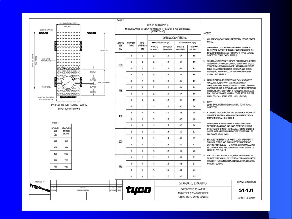


 Philadelphia University Faculty of Engineering>")


