Download presentation
Presentation is loading. Please wait.

1
نظام المحاضرات الالكترونينظام المحاضرات الالكتروني وزارة التعليم العالــي والبحث العلـــمي كلـــــــــية دجلـــــــــة الجامعــــة الأهلــــــــية قســم هندســـــــــــة تقنيــــــات الحاســـــوب فـــــــــــــرع الكـــــــــــــترونيات الحاســــــــــــــبات المرحلـــــــــــــــــــــــــــــــــــــة الــــــــــثالثــــــــــــــــــــــــة المســــيطرات الرقمـــية المتقدمـــــــة " المسيطرات الدقيقـــــــة " Advanced Digital Controllers "Microcontroller Course" Eng. Jabbar Sh. Jahlool المســــيطرات الرقمـــية المتقدمـــــــة " المسيطرات الدقيقـــــــة " Advanced Digital Controllers "Microcontroller Course" Eng. Jabbar Sh. Jahlool

2
نظام المحاضرات الالكترونينظام المحاضرات الالكتروني Introduction to Microcontrollers 1) Important Notes over Electronics. 2) What is a Microcontroller? 3) Inside Components of the Microcontroller. 4) How does the Microcontroller Work? 5) Microcontroller Vs Microprocessor. 6) Short list of MCU Brands. 7) How to choose your chip? 8) Description Of PIC16F887. 9) Necessary connections of PIC Microcontroller. 10) Outputting Data / Signals 11) Applications examples. 12) Important Displays Interfacing For PIC MCU
 What is a Microcontroller. 3) Inside Components of the Microcontroller. 4) How does the Microcontroller Work. 5) Microcontroller Vs Microprocessor. 6) Short list of MCU Brands. 7) How to choose your chip. 8) Description Of PIC16F887. 9) Necessary connections of PIC Microcontroller. 10) Outputting Data / Signals 11) Applications examples. 12) Important Displays Interfacing For PIC MCU.")
3
نظام المحاضرات الالكترونينظام المحاضرات الالكتروني 1) Important Notes over Electronics a) Pull Down Resistor Connection. b) Pull UP Resistor Connection. c) Relay Driver Circuit. d) Logic Gates. e) Test Board. a) Pull Down Resistor Connection - We use it to prevent the pin's voltage to be floating due to the noises. - When the switch is pressed, we get input HIGH on the pin "B". - When the switch isn't pressed, we get input LOW on the pin "B".
 Pull UP Resistor Connection. c) Relay Driver Circuit. d) Logic Gates. e) Test Board. a) Pull Down Resistor Connection - We use it to prevent the pin s voltage to be floating due to the noises. - When the switch is pressed, we get input HIGH on the pin B . - When the switch isn t pressed, we get input LOW on the pin B ..")
4
نظام المحاضرات الالكترونينظام المحاضرات الالكتروني b) Pull UP Resistor Connection -We use it to prevent the pin's voltage to be floating due to the noises - When the switch is pressed, we get input LOW on the pin "B". - When the switch isn't pressed, we get input HIGH on the pin "B".

5
نظام المحاضرات الالكترونينظام المحاضرات الالكتروني c) Relay Driver Circuit A Relay is an electromechanical switch, that means that it is a normal switch but it is controlled electrically using a coil.
 Relay Driver Circuit A Relay is an electromechanical switch, that means that it is a normal switch but it is controlled electrically using a coil.")
6
نظام المحاضرات الالكترونينظام المحاضرات الالكتروني Relays rating is : The value and type of the voltage applied across the coil to energize the electromagnetic field. The max current can pass through the contact without having a fault. The type and max value of the voltage applied across the contact without having a fault. Relay Driver circuit is a circuit used to allow any IC to control any load through a Relay. The Relay may require voltage or current that the IC can't afford so we use this circuit.

7
نظام المحاضرات الالكترونينظام المحاضرات الالكتروني Usage of each component: Diode: to prevent the back EMF of the relay's coil from causing damage to the Transistor. Transistor: to allow the IC to control the Relay, We use the Transistor in the saturation mode (as a switch) and this makes the IC control the Relay no matter the current or voltage required by its coil. Resistor: to limit the current passing through the base of the Transistor, so it protects the Transistor.
 and this makes the IC control the Relay no matter the current or voltage required by its coil. Resistor: to limit the current passing through the base of the Transistor, so it protects the Transistor..")
8
نظام المحاضرات الالكترونينظام المحاضرات الالكتروني d) Logic Gates It is important to be known that 1 in logic or High means 5 volt and 0 or Low means 0 volts. Also you must know that there is different forms for numbering: 1) Binary: consists of 0 and 1 only. 2) Decimal: it is the normal numbering system we are using: (0, 1, 2, 3, 4, 5, 6, 7, 8, 9) 3)Hex Decimal: consist of (0, 1, 2, 3, 4, 5, 6, 7, 8, 9, A, B, C, D, E, F) 4) Octal: consist of (0, 1, 2, 3, 4, 5, 6, 7)
 Binary: consists of 0 and 1 only. 2) Decimal: it is the normal numbering system we are using: (0, 1, 2, 3, 4, 5, 6, 7, 8, 9) 3)Hex Decimal: consist of (0, 1, 2, 3, 4, 5, 6, 7, 8, 9, A, B, C, D, E, F) 4) Octal: consist of (0, 1, 2, 3, 4, 5, 6, 7).")
9
نظام المحاضرات الالكترونينظام المحاضرات الالكتروني NOT Gate AND Gate OR Gate

10
نظام المحاضرات الالكترونينظام المحاضرات الالكتروني e) Test Boards It is a board that can be used several times as the component are fixed and can be replaced from it and its used for prototype design and testing also for practical experimental.
 Test Boards It is a board that can be used several times as the component are fixed and can be replaced from it and its used for prototype design and testing also for practical experimental.")
11
نظام المحاضرات الالكترونينظام المحاضرات الالكتروني 2) What is a Microcontroller? Embedded Systems An embedded system is a product which uses a computer to run it but the product itself is not a computer. Microcontroller (MCU) Integrated electronic computing device or a small computer on a single integrated circuit that includes three major components on a single chip Microprocessor (MPU). Memory. I/O (Input/Output) ports.
 Integrated electronic computing device or a small computer on a single integrated circuit that includes three major components on a single chip Microprocessor (MPU). Memory. I/O (Input/Output) ports..")
12
نظام المحاضرات الالكترونينظام المحاضرات الالكتروني Types of Microcontrollers: Microcontrollers can be classified on the basis of internal bus width, architecture, memory and instruction set. Figure below shows the various types of microcontrollers. - When the ALU performs arithmetic and logical operations on a byte (8- bits) at an instruction, the microcontroller is an 8-bit microcontroller. The internal bus width of 8-bit microcontroller is of 8-bit. Examples of 8-bit microcontrollers are Intel 8051 family and Motorola MC68HC11 family. - When the ALU performs arithmetic and logical operations on a word (16-bits) at an instruction, the microcontroller is an 16-bit microcontroller. The internal bus width of 16-bit microcontroller is of 16-bit. Examples of 16-bit microcontrollers are Intel 8096 family and Motorola MC68HC12 and MC68332 families. The performance and computing capability of 16 bit microcontrollers are enhanced with greater precision as compared to the 8-bit microcontrollers. - When the ALU performs arithmetic and logical operations on a double word (32- bits) at an instruction, the microcontroller is an 32-bit microcontroller. The internal bus width of 32-bit microcontroller is of 32-bit. Examples of 32-bit microcontrollers are Intel 80960 family and Motorola M683xx and Intel/Atmel 251 family.
 at an instruction, the microcontroller is an 8-bit microcontroller. The internal bus width of 8-bit microcontroller is of 8-bit. Examples of 8-bit microcontrollers are Intel 8051 family and Motorola MC68HC11 family. - When the ALU performs arithmetic and logical operations on a word (16-bits) at an instruction, the microcontroller is an 16-bit microcontroller. The internal bus width of 16-bit microcontroller is of 16-bit. Examples of 16-bit microcontrollers are Intel 8096 family and Motorola MC68HC12 and MC68332 families. The performance and computing capability of 16 bit microcontrollers are enhanced with greater precision as compared to the 8-bit microcontrollers. - When the ALU performs arithmetic and logical operations on a double word (32- bits) at an instruction, the microcontroller is an 32-bit microcontroller. The internal bus width of 32-bit microcontroller is of 32-bit. Examples of 32-bit microcontrollers are Intel family and Motorola M683xx and Intel/Atmel 251 family..")
13
نظام المحاضرات الالكترونينظام المحاضرات الالكتروني The performance and computing capability of 32 bit microcontrollers are enhanced with greater precision as compared to the 16-bit microcontrollers.

14
نظام المحاضرات الالكترونينظام المحاضرات الالكتروني Memory Architecture: All MCs use one of two basic design models - Harvard Architecture: data bus and address bus are separate. Thus a greater flow of data is possible through the CPU, and of course, a greater speed of work. - Von –Neumann (Princeton): This model use share a common bus for data and address bus.
: This model use share a common bus for data and address bus..")
15
نظام المحاضرات الالكترونينظام المحاضرات الالكتروني Microcontroller Applications: These small devices have revolutionized the world of electronics. Today microcontrollers are everywhere, think of a device and you will find a microcontroller somewhere in it. May it be your remote control, cell phone air conditioner, microwave oven, DVD player, home monitoring system, environmental control (greenhouse, factory, home) television or all have a microcontroller sitting inside. These small devices can do so much, that only imagination is the limit. Moreover they are very simple to use, you don't need to be an expert in electronics to use them in your next project. A basic understanding of electronics, and digital circuits is all that is required to get started. Once you are in the business, sky is the limit. Think of any logical application and you will find microcontroller handling the job nicely. Industrial automation including automatic assembly lines, robots and quality control systems all are backed by some kind of microcontroller.
 television or all have a microcontroller sitting inside. These small devices can do so much, that only imagination is the limit. Moreover they are very simple to use, you don t need to be an expert in electronics to use them in your next project. A basic understanding of electronics, and digital circuits is all that is required to get started. Once you are in the business, sky is the limit. Think of any logical application and you will find microcontroller handling the job nicely. Industrial automation including automatic assembly lines, robots and quality control systems all are backed by some kind of microcontroller..")
16
نظام المحاضرات الالكترونينظام المحاضرات الالكتروني Lec.2 3) Inside Components Of The Microcontroller.
 Inside Components Of The Microcontroller.")
17
نظام المحاضرات الالكترونينظام المحاضرات الالكتروني PIC MUC Components a) Central processing unit (CPU) b) Read Only Memory (ROM) c) Random Access Memory (RAM) d) Special Function Registers (SFR) e) Input /Output Ports f) Serial Communication g) Timers/Counters h) A/D Converter i) Power Supply Circuit j) Oscillator
 Central processing unit (CPU) b) Read Only Memory (ROM) c) Random Access Memory (RAM) d) Special Function Registers (SFR) e) Input /Output Ports f) Serial Communication g) Timers/Counters h) A/D Converter i) Power Supply Circuit j) Oscillator")
18
نظام المحاضرات الالكترونينظام المحاضرات الالكتروني a)Central processing unit (CPU) This is a unit which monitors and controls all processes within the microcontroller and the user cannot affect its work. It consists of several smaller subunits, of which the most important are: a) Instruction decoder b) Arithmetical Logical Unit (ALU) c) Accumulator b) Read Only Memory (ROM) Read Only Memory (ROM) is a type of memory used to permanently save the program being executed. The size of the program that can be written depends on the size of this memory. ROM can be built in the microcontroller or added as external chip, which depends on the type of the microcontroller. Today’s microcontrollers commonly use 16-bit addressing, which means that they are able to address up to 64 Kb of memory, i.e. 65535 locations. As a novice, your program will rarely exceed the limit of several hundred instructions. There are several types of ROM:-
 Instruction decoder b) Arithmetical Logical Unit (ALU) c) Accumulator b) Read Only Memory (ROM) Read Only Memory (ROM) is a type of memory used to permanently save the program being executed. The size of the program that can be written depends on the size of this memory. ROM can be built in the microcontroller or added as external chip, which depends on the type of the microcontroller. Today’s microcontrollers commonly use 16-bit addressing, which means that they are able to address up to 64 Kb of memory, i.e locations. As a novice, your program will rarely exceed the limit of several hundred instructions. There are several types of ROM:-.")
19
نظام المحاضرات الالكترونينظام المحاضرات الالكتروني Flash Memory: Flash memory is a non-volatile memory used mainly to store user programs. This type of memory can be programmed electrically while embedded on the board. Some microcontrollers have only 1 KB flash memory, while some others can have 32KB or more. In addition to computers, flash memory is also used in mobile phones and digital cameras. This type of memory was invented in the 80s in the laboratories of INTEL and was represented as the successor to the UV EPROM. Since the content of this memory can be written and cleared practically an unlimited number of times, microcontrollers with Flash ROM are ideal for learning, experimentation and small-scale production. Because of its great popularity, most microcontrollers are manufactured in flash technology today. So, if you are going to buy a microcontroller, the type to look for is definitely Flash! - MROM (Masked ROM). - UV Erasable Programmable ROM (UV EPROM). - EEPROM (Electric erasable programmable ROM).
. - UV Erasable Programmable ROM (UV EPROM). - EEPROM (Electric erasable programmable ROM)..")
20
نظام المحاضرات الالكترونينظام المحاضرات الالكتروني Random Access Memory (RAM) is a type of memory used for temporary storing data and intermediate results created and used during the operation of the microcontrollers. The content of this memory is cleared once the power supply is off. EEPROM Data Memory: EEPROM-type data memory is also very common in many microcontrollers. The advantage of an EEPROM memory is that the programmer can store nonvolatile data there and change this data whenever required. For example, in a temperature monitoring application, the maximum and minimum temperature readings can be stored in an EEPROM memory. If the power supply is removed for any reason, the values of the latest readings are available in the EEPROM memory. The PIC18F452 microcontroller has 256 bytes of EEPROM memory. Other members of the PIC18F family have more EEPROM memory (e.g., the PIC18F6680 has 1024 bytes). The mikroC language provides special instructions for reading and writing to the EEPROM memory of a PIC microcontroller. c) Random Access Memory (RAM)
. The mikroC language provides special instructions for reading and writing to the EEPROM memory of a PIC microcontroller. c) Random Access Memory (RAM).")
21
نظام المحاضرات الالكترونينظام المحاضرات الالكتروني d) Registers & Special Function Registers (SFR) Register: In short, a register or a memory cell is an electronic circuit which can memorize the state of one byte. Special Function Registers (SFR) Special Function Registers are part of RAM memory. In addition to registers which do not have any special and predetermined function, every microcontroller has a number of registers (SFR) whose function is predetermined by the manufacturer. Their bits are physically connected to particular circuits within the micro- controller such as timers, A/D converter, oscillators etc.,
 Special Function Registers are part of RAM memory. In addition to registers which do not have any special and predetermined function, every microcontroller has a number of registers (SFR) whose function is predetermined by the manufacturer. Their bits are physically connected to particular circuits within the micro- controller such as timers, A/D converter, oscillators etc.,.")
22
نظام المحاضرات الالكترونينظام المحاضرات الالكتروني -Any change of their state affects the operation of the microcontroller or some of the circuits e) Input /Output Ports In order to make the microcontroller useful, it has to be connected to additional electronics, i.e. peripherals. Each microcontroller has one or more registers (called a port) connected to the microcontroller pins. So the microcontroller will be connected to the peripheral devices through the pins connected the port register. The port registers are controlled to be input or output using registers called TRIS registers, so each port has its on TRIS register.
 connected to the microcontroller pins. So the microcontroller will be connected to the peripheral devices through the pins connected the port register. The port registers are controlled to be input or output using registers called TRIS registers, so each port has its on TRIS register..")
23
نظام المحاضرات الالكترونينظام المحاضرات الالكتروني So any bit in a PORTx can be input if the equivalent bit in the TIRSx register is (1) and output if the equivalent bit in the TRISx register is (0). Current sink/source capability is important if the microcontroller is to be connected to an external device that might draw a large amount of current to operate. PIC microcontrollers can source and sink 25mA of current from each output port pin. This current is usually sufficient to drive LEDs, small lamps, buzzers, small relays, etc. The current capability can be increased by connecting external transistor switching circuits or relays to the output port pins.

24
نظام المحاضرات الالكترونينظام المحاضرات الالكتروني f) Serial Communication Parallel connection between the microcontroller and peripherals via input/output ports is the ideal solution on shorter distances up to several meters. However, in other cases when it is necessary to establish communication between two devices on longer distances it is not possible to use parallel connection. Instead, serial communication is used. Serial Input-Output or Serial communication (also called RS232 communication) enables a microcontroller to be connected to another microcontroller or to a PC using a serial cable. Some microcontrollers have built-in hardware called USART (universal synchronous asynchronous receiver- transmitter) to implement a serial communication interface.
 enables a microcontroller to be connected to another microcontroller or to a PC using a serial cable. Some microcontrollers have built-in hardware called USART (universal synchronous asynchronous receiver- transmitter) to implement a serial communication interface..")
25
نظام المحاضرات الالكترونينظام المحاضرات الالكتروني Today, most microcontrollers have built in several different systems for serial communication as a standard equipment. Which of these systems will be used depends on many factors of which the most important are: -How many devices the microcontroller has to exchange data with? - How fast the data exchange has to be? - What is the distance between devices? -Is it necessary to send and receive data simultaneously?

26
نظام المحاضرات الالكترونينظام المحاضرات الالكتروني One of the most important things concerning serial communication is the Protocol which should be strictly observed. It is a set of rules which must be applied in order that devices can correctly interpret data they mutually exchange. Fortunately, the microcontroller automatically takes care of this, so that the work of the programmer/user is reduced to simple write (data to be sent) and read (received data). Baud Rate: The term baud rate is used to denote the number of bits transferred per second [bps]. Note that it refers to bits, not bytes. It is usually required by the protocol that each byte is transferred along with several control bits. It means that one byte in serial data stream may consist of 11 bits. For example, if the baud rate is 300 bps then maximum 37 and minimum 27 bytes may be transferred per second. The most commonly used serial communication systems are:
 and read (received data). Baud Rate: The term baud rate is used to denote the number of bits transferred per second [bps]. Note that it refers to bits, not bytes. It is usually required by the protocol that each byte is transferred along with several control bits. It means that one byte in serial data stream may consist of 11 bits. For example, if the baud rate is 300 bps then maximum 37 and minimum 27 bytes may be transferred per second. The most commonly used serial communication systems are:.")
27
نظام المحاضرات الالكترونينظام المحاضرات الالكتروني 1) I²C (Inter Integrated Circuit) Inter-integrated circuit is a system for serial data exchange between the microcontrollers and specialized integrated circuits of a new generation. It is used when the distance between them is short (receiver and transmitter are usually on the same printed board). Connection is established via two conductors. One is used for data transfer, the other is used for synchronization (clock signal). As seen in figure below, one device is always a master. It performs addressing of one slave chip before communication starts. In this way one microcontroller can communicate with 112 different devices. Baud rate is usually 100 Kb/sec (standard mode) or 10 Kb/sec (slow baud rate mode). Systems with the baud rate of 3.4 Mb/sec have recently appeared. The distance between devices which communicate over an I2C bus is limited to several meters.
. Connection is established via two conductors. One is used for data transfer, the other is used for synchronization (clock signal). As seen in figure below, one device is always a master. It performs addressing of one slave chip before communication starts. In this way one microcontroller can communicate with 112 different devices. Baud rate is usually 100 Kb/sec (standard mode) or 10 Kb/sec (slow baud rate mode). Systems with the baud rate of 3.4 Mb/sec have recently appeared. The distance between devices which communicate over an I2C bus is limited to several meters..")
28
نظام المحاضرات الالكترونينظام المحاضرات الالكتروني 2) SPI (Serial Peripheral Interface Bus) A serial peripheral interface (SPI) bus is a system for serial communication which uses up to four conductors, commonly three. One conductor is used for data receiving, one for data sending, one for synchronization and one alternatively for selecting a device to communicate with. It is a full duplex connection, which means that data is sent and received simultaneously. The maximum baud rate is higher than that in the I2C communication system.

29
نظام المحاضرات الالكترونينظام المحاضرات الالكتروني Lec-3 3) UART (Universal Asynchronous Receiver/ Transmitter) This sort of communication is asynchronous, which means that a special line for transferring clock signal is not used. In some applications, such as radio connection or infrared waves remote control, this feature is crucial. Since only one communication line is used, both receiver and transmitter operate at the same predefined rate in order to maintain necessary synchronization. This is a very simple way of transferring data since it basically represents the conversion of 8-bit data from parallel to serial format. Baud rate is not high, up to 1 Mbit/sec. g) Timers/Counters The microcontroller oscillator uses quartz crystal for its operation. Even though it is not the simplest solution, there are many reasons to use it.
 Timers/Counters The microcontroller oscillator uses quartz crystal for its operation. Even though it is not the simplest solution, there are many reasons to use it..")
30
نظام المحاضرات الالكترونينظام المحاضرات الالكتروني The frequency of such oscillator is precisely defined and very stable, so that pulses it generates are always of the same width, which makes them ideal for time measurement. Such oscillators are also used in quartz watches. If it is necessary to measure time between two events, it is sufficient to count up pulses generated by this oscillator. This is exactly what the timer does.

31
نظام المحاضرات الالكترونينظام المحاضرات الالكتروني Most programs use these miniature electronic ‘stopwatches’. These are commonly 8- or 16-bit SFRs the contents of which is automatically incremented by each coming pulse. Once a register is completely loaded, an interrupt may be generated!. If the timer uses an internal quartz oscillator for its operation then it can be used to measure time between two events (if the register value is T1 at the moment measurement starts, and T2 at the moment it terminates, then the elapsed time is equal to the result of subtraction T2-T1). If registers use pulses coming from external source then such a timer is turned into a counter. This is only a simple explanation of the operation itself. It is however more complicated in practice.
. If registers use pulses coming from external source then such a timer is turned into a counter. This is only a simple explanation of the operation itself. It is however more complicated in practice..")
32
نظام المحاضرات الالكترونينظام المحاضرات الالكتروني How Does the Timer Operate? In practice, pulses generated by the quartz oscillator are once per each machine cycle, directly or via a prescaler, brought to the circuit which increments the number stored in the timer register. If one instruction (one machine cycle) lasts for four quartz oscillator periods then this number will be incremented a million times per second (each microsecond) by embedding quartz with the frequency of 4MHz.
 lasts for four quartz oscillator periods then this number will be incremented a million times per second (each microsecond) by embedding quartz with the frequency of 4MHz..")
33
نظام المحاضرات الالكترونينظام المحاضرات الالكتروني It is easy to measure short time intervals, up to 256 microseconds, in the way described above because it is the largest number that one register can store. This restriction may be easily overcome in several ways such as by using a slower oscillator, registers with more bits, prescaler or interrupts. The first two solutions have some weaknesses so it is more recommended to use prescalers or interrupts. Using a Prescaler in Timer Operation: A prescaler is an electronic device used to reduce frequency by a predetermined factor. In order to generate one pulse on its output, it is necessary to bring 1, 2, 4 or more pulses on its input. Most microcontrollers have one or more prescalers built in and their division rate may be changed from within the program. The prescaler is used when it is necessary to measure longer periods of time. If one prescaler is shared by timer and watchdog timer, it cannot be used by both of them simultaneously.

34
نظام المحاضرات الالكترونينظام المحاضرات الالكتروني Most microcontrollers have one or more prescalers built in and their division rate may be changed from within the program. The prescaler is used when it is necessary to measure longer periods of time. If one prescaler is shared by timer and watchdog timer, it cannot be used by both of them simultaneously.

35
نظام المحاضرات الالكترونينظام المحاضرات الالكتروني Using Interrupt in Timer Operation : If the timer register consists of 8 bits, the largest number it can store is 255. As for 16-bit registers it is the number 65.535. If this number is exceeded, the timer will be automatically reset and counting will start at zero again. This condition is called an overflow. If enabled from within the program, the overflow can cause an interrupt, which gives completely new possibilities. For example, the state of registers used for counting seconds, minutes or days can be changed in an interrupt routine. The whole process (except for interrupt routine) is automatically performed behind the scenes, which enables the main circuits of the microcontroller to operate normally.
 is automatically performed behind the scenes, which enables the main circuits of the microcontroller to operate normally..")
36
نظام المحاضرات الالكترونينظام المحاضرات الالكتروني This figure illustrates the use of an interrupt in timer operation. Delays of arbitrary duration, having almost no influence on the main program execution, can be easily obtained by assigning the prescaler to the timer. Counters: If the timer receives pulses from the microcontroller input pin, then it turns into a counter. Obviously, it is the same electronic circuit able to operate in two different modes. The only difference is that in this case pulses to be counted come over the microcontroller input pin and their duration (width) is mostly undefined. This is why they cannot be used for time measurement, but for other purposes such as counting products on an assembly line, number of axis rotation, passengers etc. (depending on sensor in use).
 is mostly undefined. This is why they cannot be used for time measurement, but for other purposes such as counting products on an assembly line, number of axis rotation, passengers etc. (depending on sensor in use)..")
37
نظام المحاضرات الالكترونينظام المحاضرات الالكتروني h) A/D Converter`` which converts continuous signals to discrete digital numbers. In other words, this circuit converts an analogue value into a binary number and passes it to the CPU for further processing. This module is therefore used for input pin voltage measurement (analogue value). The result of measurement is a number (digital value) used and processed later in the program. A/D converters are especially useful in control and monitoring applications, since most sensors (e.g., temperature sensors, pressure sensors, force sensors, etc.) produce analog output voltages. External signals are usually fundamentally different from those the microcontroller understands (ones and zeros) and have to be converted therefore into values understandable for the microcontroller. An analogue to digital converter is an electronic circuit
. The result of measurement is a number (digital value) used and processed later in the program. A/D converters are especially useful in control and monitoring applications, since most sensors (e.g., temperature sensors, pressure sensors, force sensors, etc.) produce analog output voltages. External signals are usually fundamentally different from those the microcontroller understands (ones and zeros) and have to be converted therefore into values understandable for the microcontroller. An analogue to digital converter is an electronic circuit.")
38
نظام المحاضرات الالكترونينظام المحاضرات الالكتروني i) Power Supply Circuit There are two things worth attention concerning the microcontroller power supply circuit: - Brown Out - Reset Pin Brown Out: - It is a potentially dangerous state which occurs when the microcontroller is being turned off or when power supply voltage drops to the lowest level due to electric noise.
 Power Supply Circuit There are two things worth attention concerning the microcontroller power supply circuit: - Brown Out - Reset Pin Brown Out: - It is a potentially dangerous state which occurs when the microcontroller is being turned off or when power supply voltage drops to the lowest level due to electric noise.")
39
نظام المحاضرات الالكترونينظام المحاضرات الالكتروني j) Oscillator Even pulses generated by the oscillator enable the operation of all circuits within the microcontroller. One of the factors that controls the speed of the microcontroller is the frequency of the oscillator. There are different modes of oscillators like: Low Power Crystal (LP) Crystal/Resonator (XT) High Speed Crystal/Resonator (HS) Resistor Capacitor (RC) - As the microcontroller consists of several circuits which have different operating voltage levels, this can cause its out of control performance. This circuit immediately resets the whole electronics when the voltage level drops below the lower limit. Reset Pin Master Clear Reset (MCLR) serves for external reset of the microcontroller. Reset puts the microcontroller into a known state. Usually, after a reset, the program starting from memory address 0 of the microcontroller is executed.
 Crystal/Resonator (XT) High Speed Crystal/Resonator (HS) Resistor Capacitor (RC) - As the microcontroller consists of several circuits which have different operating voltage levels, this can cause its out of control performance. This circuit immediately resets the whole electronics when the voltage level drops below the lower limit. Reset Pin Master Clear Reset (MCLR) serves for external reset of the microcontroller. Reset puts the microcontroller into a known state. Usually, after a reset, the program starting from memory address 0 of the microcontroller is executed..")
40
نظام المحاضرات الالكترونينظام المحاضرات الالكتروني - We use capacitors with the oscillators to reduce noises and we chose the capacitors values depending on the oscillator frequency and type. -It is important to say that program instructions are not executed at the rate imposed by the oscillator. -There are four steps taken by the CPU to do an instruction: 1. Fetch 2. Decode 3. Execute 4. Transfer F internal-clock = 1/ F osc T cycle = 4 * T osc = T fetch + T decode + T execute + T transfer

41
نظام المحاضرات الالكترونينظام المحاضرات الالكتروني 4) How does the microcontroller work? The program is load into the microcontroller. Power supply is turned on, the control logic units disables all other circuits except quartz crystal to operate. Power supply voltage reaches its maximum and oscillator frequency becomes stable. SFRs are being filled with bits reflecting the state of all circuits within the microcontroller. Program counter is set to zero. Instruction from that address is sent to instruction decoder which recognizes it, after which it is executed with immediate effect. The value of the program counter is incremented by (1) and the whole process is repeated several million times per second.
 and the whole process is repeated several million times per second..")
42
نظام المحاضرات الالكترونينظام المحاضرات الالكتروني 5) Microcontroller Vs Microprosser Microcontroller contains a Microprocessor.
 Microcontroller Vs Microprosser Microcontroller contains a Microprocessor.")
43
نظام المحاضرات الالكترونينظام المحاضرات الالكتروني Microprocessor is a single chip CPU, microcontroller contains, a CPU and much of the remaining circuitry of a complete microcomputer system in a single chip. Microcontroller includes RAM, ROM, serial and parallel interface, timer, interrupt schedule circuitry (in addition to CPU) in a single chip. RAM is smaller than that of even an ordinary microcomputer, but enough for its applications. Interrupt system is an important feature, as microcontrollers have to respond to control oriented devices in real time. E.g., opening of microwave oven’s door cause an interrupt to stop the operation. (Most microprocessors can also implement powerful interrupt schemes, but external components are usually needed). Microprocessors are most commonly used as the CPU in microcomputer systems. Microcontrollers are used in small, minimum component designs performing control- oriented activities. Microprocessor instruction sets are processing intensive, implying powerful addressing modes with instructions catering to large volumes of data. Their instructions operate on nibbles, bytes, etc. Microcontrollers have instruction sets catering to the control of inputs and outputs. Their instructions operate also on a single bit. E.g., a motor may be turned ON and OFF by a 1-bit output port.
 in a single chip. RAM is smaller than that of even an ordinary microcomputer, but enough for its applications. Interrupt system is an important feature, as microcontrollers have to respond to control oriented devices in real time. E.g., opening of microwave oven’s door cause an interrupt to stop the operation. (Most microprocessors can also implement powerful interrupt schemes, but external components are usually needed). Microprocessors are most commonly used as the CPU in microcomputer systems. Microcontrollers are used in small, minimum component designs performing control- oriented activities. Microprocessor instruction sets are processing intensive, implying powerful addressing modes with instructions catering to large volumes of data. Their instructions operate on nibbles, bytes, etc. Microcontrollers have instruction sets catering to the control of inputs and outputs. Their instructions operate also on a single bit. E.g., a motor may be turned ON and OFF by a 1-bit output port..")
44
نظام المحاضرات الالكترونينظام المحاضرات الالكتروني 6) How to choose your chip? Logically: Decide the type and number of the modules in the microcontroller you will need in your project. Check up the microcontrollers available in the market. Look for the data sheet for each of them to get the one that you need (look it up in the library of the software proteus easier than the internet).
..")
45
نظام المحاضرات الالكترونينظام المحاضرات الالكتروني 7) Short list of MCU Brands
 Short list of MCU Brands")
46
نظام المحاضرات الالكترونينظام المحاضرات الالكتروني Lec-4 8) PIC16F887 description
 PIC16F887 description")
47
نظام المحاضرات الالكترونينظام المحاضرات الالكتروني PIC16F887 Pin Configuration

48
نظام المحاضرات الالكترونينظام المحاضرات الالكتروني 9) Necessary connections for PIC16F887 Connect Pin 11 and 32 to the Vcc and Pin 12 and 31 to the GND. Connect Pin 1 (MCLR) to a pull down resistor connection.
 to a pull down resistor connection..")
49
نظام المحاضرات الالكترونينظام المحاضرات الالكتروني Connect pin 13 and 14 to the oscillator and two capacitors like the figure.

50
نظام المحاضرات الالكترونينظام المحاضرات الالكتروني C Programming Language 1) Introduction to Programming 2) mikroC Compiler 3) Structure of a Simple Program 4) Variables & Constants 5) Arrays 6) Operators 7) Flow Control 8) Functions 9) Notes
 Introduction to Programming 2) mikroC Compiler 3) Structure of a Simple Program 4) Variables & Constants 5) Arrays 6) Operators 7) Flow Control 8) Functions 9) Notes")
51
نظام المحاضرات الالكترونينظام المحاضرات الالكتروني 1) Introduction to Programming Programming is writing the instruction that the Microprocessor will do. At first programs were written in Machine Code (0, 1). Then Assembly Language was invented as the hardware became complex and we needed to make an easier language. Then the higher level languages were invented, They are much easier than assembly Language (C, Java). The microcontroller executes the program loaded in its Flash memory. This is so called executable code (sequence of zeros and ones). It is organized in 12-, 14- or 16-bit wide words, depending on the microcontroller’s architecture. Every word is considered by the CPU as a command being executed during the operation of the microcontroller. For practical reasons, as it is much easier for us to deal with hexadecimal number system, the executable code is often represented as a sequence of hexadecimal numbers called a Hex code. It used to be written by the programmer. All instructions that the microcontroller can recognize are to gather called the Instruction set. As for PIC microcontrollers the programming words of which are comprised of 14 bits, the instruction set has 35 different instructions in total.
. Then Assembly Language was invented as the hardware became complex and we needed to make an easier language. Then the higher level languages were invented, They are much easier than assembly Language (C, Java). The microcontroller executes the program loaded in its Flash memory. This is so called executable code (sequence of zeros and ones). It is organized in 12-, 14- or 16-bit wide words, depending on the microcontroller’s architecture. Every word is considered by the CPU as a command being executed during the operation of the microcontroller. For practical reasons, as it is much easier for us to deal with hexadecimal number system, the executable code is often represented as a sequence of hexadecimal numbers called a Hex code. It used to be written by the programmer. All instructions that the microcontroller can recognize are to gather called the Instruction set. As for PIC microcontrollers the programming words of which are comprised of 14 bits, the instruction set has 35 different instructions in total..")
52
نظام المحاضرات الالكترونينظام المحاضرات الالكتروني

53
2) MikroC Complier The first thing you need to write a program for the microcontroller is a PC program which understands the programming language you use, C in this case, and provides a window for writing program. Besides, the software must 'know' the architecture of the microcontroller in use. In this case, you need a compiler for C language. There is no compiler to be used for only one concrete microcontroller as there is no compiler to be used for all microcontrollers. It’s all about software used to program a group of similar microcontrollers of one manufacturer compiler. As the name suggests, the compiler is intended for writing programs for PIC microcontrollers in C language. It is provided with all data on internal architecture of these microcontrollers, operation of particular circuits, instruction set, names of registers, their accurate addresses, pin outs etc. When you start up the compiler, the next thing to do is to select a chip from the list and operating frequency and of course - to write a program in C language.

54
نظام المحاضرات الالكترونينظام المحاضرات الالكتروني 3) Variables and Constants a) Why using Variables and Constants?! b) How to declare a Variable? c) Variable Types. d) Variable Name. e) Examples of Variable declaration. f) Constants declaration. a) Why using Variables and Constants?! -We use Variables and constants to store the data of the program and deal with them like doing mathematical operations or displaying their values. -Variables are stored in RAM so we can change their values during the program. -Constants are stored in ROM so we can't change their values during the program.
 How to declare a Variable. c) Variable Types. d) Variable Name. e) Examples of Variable declaration. f) Constants declaration. a) Why using Variables and Constants . -We use Variables and constants to store the data of the program and deal with them like doing mathematical operations or displaying their values. -Variables are stored in RAM so we can change their values during the program. -Constants are stored in ROM so we can t change their values during the program..")
55
نظام المحاضرات الالكترونينظام المحاضرات الالكتروني b) How to declare a Variable? To declare a variable we need to describe the following: 1. Variable Type. 2. Variable name. 3. Value of the Variable (not a must). And we write the declaration statement like this: Variable Type Variable name = Variable Value;
. And we write the declaration statement like this: Variable Type Variable name = Variable Value;.")
56
نظام المحاضرات الالكترونينظام المحاضرات الالكتروني c) Variable Types
 Variable Types")
57
نظام المحاضرات الالكترونينظام المحاضرات الالكتروني d) Variable Name Variable Names must be Unique. Variable Names must begin with alphabetical characters (uppercase or lowercase) or Underscore characters. It may contain numbers and can contain uppercase or lowercase characters. Variable Names must not be like the reserved names of the compiler. It must not contain any special characters like ( ) : ; _ " ' & % $ # } [ { ]. Examples: Correct Variable Names: (sum, Result, student_1, Student4, _sum). Wrong Variable Names: (5student, 5_student, #sum, if, switch, while, enum, case, else, asm, goto..... e) Examples of Variable Declaration int x ; char n = 'A' ; float sum = 0 ; long z =12 ; Int L = 0b110011 ;
 or Underscore characters. It may contain numbers and can contain uppercase or lowercase characters. Variable Names must not be like the reserved names of the compiler. It must not contain any special characters like ( ) : ; _ & % $ # } [ { ]. Examples: Correct Variable Names: (sum, Result, student_1, Student4, _sum). Wrong Variable Names: (5student, 5_student, #sum, if, switch, while, enum, case, else, asm, goto..... e) Examples of Variable Declaration int x ; char n = A ; float sum = 0 ; long z =12 ; Int L = 0b ;.")
58
نظام المحاضرات الالكترونينظام المحاضرات الالكتروني f) Constant Declaration Declaring a constant is just like declaring a variable, we just put the word const before the variable type. As we can't change the value of the constants during the program so we must put their value when declaring them. Examples: const int x = 5 ; const char ch_1 = 'L' ; 4) Arrays a) What are Arrays and why using them? b) How to declare an array?
 Arrays a) What are Arrays and why using them. b) How to declare an array .")
59
نظام المحاضرات الالكترونينظام المحاضرات الالكتروني a) What are Arrays and why using them? Array used to store elements with the same type in memory. We may use arrays to one operation to more than a couple of variables like adding three number to an other three numbers in the same time. Arrays will help you to store and handle data easily during the program such as in loops and many other uses. b) How to declare an array?
 How to declare an array .")
60
نظام المحاضرات الالكترونينظام المحاضرات الالكتروني 5) Operators
 Operators")
61
نظام المحاضرات الالكترونينظام المحاضرات الالكتروني

63
Lec-5

64
نظام المحاضرات الالكترونينظام المحاضرات الالكتروني 6) Flow Control Selection statement: if switch Interation statement: while for do while Unconditional statement: goto break Selection statment "if" if (condition1) { Statement1; } else if (condition2)
 Flow Control Selection statement: if switch Interation statement: while for do while Unconditional statement: goto break Selection statment if if (condition1) { Statement1; } else if (condition2)")
65
نظام المحاضرات الالكترونينظام المحاضرات الالكتروني If condition1happend dostatement1. If condition2happend dostatement2. If non of themhappend dostatement3. Example: if(x==1) { Portb.f0 = 1; } else if (x==92&& L==91) { Portb.f1=1; } else Portb.f3=1;
 { Portb.f0 = 1; } else if (x==92&& L==91) { Portb.f1=1; } else Portb.f3=1;.")
66
نظام المحاضرات الالكترونينظام المحاضرات الالكتروني Selection statment "switch" switch(x) { case condition1: statement1; case condition2: Statement2; defult: Statement3; } Check the variable x. If it is equal to condition1 do statement1. If it is equal to condition2 do statement2. If condition1 or condition2 didn't happen do statement3. Example:

67
نظام المحاضرات الالكترونينظام المحاضرات الالكتروني

68
If condition1 occurs, do statement1 until it changes. Example: while (L<=4) { Portc.f4=1; L++; } Iteration statment "for" for (initial expression; condition expression; increment expression) { Statement1; } Example: for (i=1; i<4; i++) { x++; }
 { Portc.f4=1; L++; } Iteration statment for for (initial expression; condition expression; increment expression) { Statement1; } Example: for (i=1; i<4; i++) { x++; }.")
69
نظام المحاضرات الالكترونينظام المحاضرات الالكتروني It will begin with i = 1 then it will check if it is less than 4 and if this true it will do x++ then increments i with 1 and then checks if the new value of i is less than 4 or not if it was true it will do x++ then increments i with 1 and so on until i is equal or greater than 4 it will not do the loop and continue the program. Iteration statment "do while" do{ Statement1; } while(condition1) It will do statement 1 then checks if condition 1 is happening it will continue in the loop until condition 1 don't occur. Example: do{ x++; } while(x<10);
 It will do statement 1 then checks if condition 1 is happening it will continue in the loop until condition 1 don t occur. Example: do{ x++; } while(x<10);.")
70
نظام المحاضرات الالكترونينظام المحاضرات الالكتروني Unconditional statment "goto" start: statement1; goto start; goto makes the program jump to the label called after it. Example: Lamp: x++; goto lamp; Unconditional statment "break" It breaks the flow of a part in the program. In the next example if y equal to 5 the processor will not continue the loop and breaks it and will do the rest of the program. Example: for (x = 4; x < 40; x ++) { y++; if (y == 5) break; }
 { y++; if (y == 5) break; }.")
71
نظام المحاضرات الالكترونينظام المحاضرات الالكتروني 7) Functions What is a function? How to Declare a function? Example. -- What is a function? A function is a process which is outside the main function of the program and you can use it in the main function. It is similar to a function in Math - but not exactly the same -, it has input values and it does some kind of operations on it then it gives you an output. -- How to Declare a function? To declare a function we must put: 1.The Function's name. 2.What parameters will the function have as input (number of them and their type). 3. What parameters will the function return as an output (Type).
. 3. What parameters will the function return as an output (Type)..")
72
نظام المحاضرات الالكترونينظام المحاضرات الالكتروني Example int square (int x) In this example we here declared: Name of the function as square. It have one input parameter. The input parameter is integer. Its output is also an integer. int anything (int x, char y) In this example we here declared: Name of the function as anything. It have two input parameters. The input parameter is integer and the other one is char. Its output is also an integer.
 In this example we here declared: Name of the function as anything. It have two input parameters. The input parameter is integer and the other one is char. Its output is also an integer..")
73
نظام المحاضرات الالكترونينظام المحاضرات الالكتروني Note that: If you don't want the function to have any input parameters you should leave the two brackets empty ( ) or write (void) between them. Example: int sum ( ), int sum (void). If you don't want the function to return any parameters you will write void instead of the type that it returns. Example: void sum (int x), void sum ( ). 8 ) Structure Of Simple Program Figure below illustrates the structure of a simple program, pointing out the parts.
, int sum (void). If you don t want the function to return any parameters you will write void instead of the type that it returns. Example: void sum (int x), void sum ( ). 8 ) Structure Of Simple Program Figure below illustrates the structure of a simple program, pointing out the parts..")
74
نظام المحاضرات الالكترونينظام المحاضرات الالكتروني

75
9) Notes
 Notes")
76
نظام المحاضرات الالكترونينظام المحاضرات الالكتروني 10)Outputting Data / Signals Microcontrollers have dual worlds. An internal world; comprising of registers, timers, CPU and other integrated devices, and an external world, which consists of other devices, like LCD, Keypads, speakers, sensors and what not. In order to communicate with these devices microcontroller uses its pins, also called I/O lines. The number of these I/O lines is one of the major characteristics of a microcontroller. PIC16F887 microcontroller, which is 40 pin device, it has one MCLR pin, 4 Power supply and two for oscillator. The rest of 33 I/O lines are available for connection to other devices. In order pins’ operation can match internal 8-bit organization, all of them are, similar to registers, grouped into five so called ports denoted by A, B, C, D and E. All of them have several features in common:

77
نظام المحاضرات الالكترونينظام المحاضرات الالكتروني For practical reasons, many I/O pins have two or three functions. In case any of these alternate functions is currently active, that pin may not simultaneously use as a general purpose input/output pin. Every port has its “satellite”, i.e. the corresponding TRIS register: TRISA, TRISB, TRISC etc. which determines performance, but not the contents of the port bits. By clearing some bit of the TRIS register (bit=0), the corresponding port pin is configured as output. Similarly, by setting some bit of the TRIS register (bit=1), the corresponding port pin is configured as input. This rule is easy to remember 0 = Output, 1 = Input.
, the corresponding port pin is configured as output. Similarly, by setting some bit of the TRIS register (bit=1), the corresponding port pin is configured as input. This rule is easy to remember 0 = Output, 1 = Input..")
78
نظام المحاضرات الالكترونينظام المحاضرات الالكتروني Analog and Digital Pins PIC16F887 has a number of pins, which can acquire analog data. The same pins however can also be configured as digital, if not to be used as analog. PORTA and TRISA register PORTA is an 8-bit wide, bidirectional port. Bits of the TRISA and ANSEL registers control the PORTA pins. All PORTA pins act as digital inputs/outputs. Five of them can also be analog inputs (denoted by AN):
:.")
79
نظام المحاضرات الالكترونينظام المحاضرات الالكتروني RA0 = AN0 (determined by the ANS0 bit of the ANSELregister) RA1 = AN1 (determined by the ANS1 bit of the ANSELregister) RA2 = AN2 (determined by the ANS2 bit of the ANSELregister) RA3 = AN3 (determined by the ANS3 bit of the ANSELregister) RA5 = AN4 (determined by the ANS4 bit of the ANSELregister) Similar to bits of the TRISA register determine which of the pins are to be configured as inputs and which ones as outputs, the appropriate bits of the ANSEL register determine whether pins are to be configured as analog inputs or digital inputs/outputs. Let's do it in mikroC...

80
نظام المحاضرات الالكترونينظام المحاضرات الالكتروني Lec-6 PORTB and TRISB register Similar to PORTA, a logic one (1) in the TRISB register configures the appropriate PORTB pin as an input and vice versa. Six pins of this port can act as analog inputs (AN). The bits of the ANSELH register determine whether these pins are to be configured as analog inputs or digital inputs/outputs
. The bits of the ANSELH register determine whether these pins are to be configured as analog inputs or digital inputs/outputs.")
81
نظام المحاضرات الالكترونينظام المحاضرات الالكتروني RB0 = AN12 (determined by the ANS12 bit of the ANSELH register) RB1 = AN10 (determined by the ANS10 bit of the ANSELH register) RB2 = AN8 (determined by the ANS8 bit of the ANSELH register) RB3 = AN9 (determined by the ANS9 bit of the ANSELH register) RB4 = AN11 (determined by the ANS11 bit of the ANSELH register) RB5 = AN13 (determined by the ANS13 bit of the ANSELH register) This port has several features which distinguish it from other ports and make its pins commonly used: All the PORTB pins have built in pull-up resistors, which make them ideal for connection to push buttons (keyboard), switches and optocoupllers. In order to connect these resistors to the microcontroller ports, the appropriate bit of the WPUB register should be set.*

82
نظام المحاضرات الالكترونينظام المحاضرات الالكتروني Having a high level of resistance (several tens of kiloohms), these ‘virtual’ resistors do not affect pins configured as outputs, but serves as a useful complement to inputs. As such, they are connected to the inputs of CMOS logic circuits. Otherwise, they would act as if they are floating due to their high input resistance.

83
نظام المحاضرات الالكترونينظام المحاضرات الالكتروني * Apart from the bits of the WPUB register, there is another bit affecting the installation of all pull-up resistors. It is the RBPU bit of the OPTION_REG. If enabled, each PORTB bit configured as an input may cause an interrupt by

84
نظام المحاضرات الالكترونينظام المحاضرات الالكتروني changing its logic state. In order to enable pins to cause an interrupt, the appropriate bit of the IOCB register should be set. The PORTB pins are commonly used for checking push buttons on the keyboard because they unerringly register any button press. Thus, there is no need to ‘scan’ these inputs all the time.

85
نظام المحاضرات الالكترونينظام المحاضرات الالكتروني When the X, Y and Z pins are configured as outputs set to logic one (1), it is only necessary to wait for an interrupt request which arrives upon any button press. After that, by combining zeros and ones on these outputs it is checked which push button is pressed. Let's do it in mikroC...

86
نظام المحاضرات الالكترونينظام المحاضرات الالكتروني PIN RB0/INT The RB0/INT pin is the only ‘true’ external interrupt source. It can be configured to react to signal raising edge (zero-to-one transition) or signal falling edge (one- to-zero transition). The INTEDG bit of the OPTION_REG register selects the appropriate signal.
 or signal falling edge (one- to-zero transition). The INTEDG bit of the OPTION_REG register selects the appropriate signal..")
87
نظام المحاضرات الالكترونينظام المحاضرات الالكتروني PORTC and TRISC register PORTC is an 8-bit wide, bidirectional port. Bits of the TRISC register determine the function of its pins. Similar to other ports, a logic one (1) in the TRISC register configures the appropriate PORTC pin as an input.
 in the TRISC register configures the appropriate PORTC pin as an input..")
88
نظام المحاضرات الالكترونينظام المحاضرات الالكتروني PORTD and TRISD register PORTD is an 8-bit wide, bidirectional port. Bits of the TRISD register determine the function of its pins. A logic one (1) in the TRISD register configures the appropriate PORTD pin as an input.
 in the TRISD register configures the appropriate PORTD pin as an input..")
89
نظام المحاضرات الالكترونينظام المحاضرات الالكتروني PORTE and TRISE register Port E is a 4-bit wide, bidirectional port. The TRISE register’s bits determine the function of its pins. Similar to other ports, a logic one (1) in the TRISE register configures the appropriate PORTE pin as an input. The exception is the RE3 pin which is always configured as an input. Similar to ports A and B, three pins can be configured as analog inputs in this case. The ANSELH register bits determine whether a pin will act as an analog input (AN) or digital input/output: RE0 = AN5 (determined by the ANS5 bit of the ANSELregister); RE1 = AN6 (determined by the ANS6 bit of the ANSELregister); and RE2 = AN7 (determined by the ANS7 bit of the ANSELregister).
 in the TRISE register configures the appropriate PORTE pin as an input. The exception is the RE3 pin which is always configured as an input. Similar to ports A and B, three pins can be configured as analog inputs in this case. The ANSELH register bits determine whether a pin will act as an analog input (AN) or digital input/output: RE0 = AN5 (determined by the ANS5 bit of the ANSELregister); RE1 = AN6 (determined by the ANS6 bit of the ANSELregister); and RE2 = AN7 (determined by the ANS7 bit of the ANSELregister)..")
90
نظام المحاضرات الالكترونينظام المحاضرات الالكتروني ANSEL and ANSELH register The ANSEL and ANSELH registers are used to configure the input mode of an I/O pin to analog or digital. The rule is: To configure a pin as an analog input, the appropriate bit of the ANSEL or ANSELH registers must be set (1). To configure a pin as a digital input/output, the appropriate bit must be cleared (0). The state of the ANSEL bits has no influence on digital output functions. The result of any attempt to read a port pin configured as an analog input will be 0.
. To configure a pin as a digital input/output, the appropriate bit must be cleared (0). The state of the ANSEL bits has no influence on digital output functions. The result of any attempt to read a port pin configured as an analog input will be 0..")
91
نظام المحاضرات الالكترونينظام المحاضرات الالكتروني In Short When designing a device, select a port through which the microcontroller will communicate to peripheral environment. If you use only digital inputs/outputs, select any port you want. If you intend to use some of the analog inputs, select the appropriate ports supporting such a pin configuration (AN0-AN13).
..")
92
نظام المحاضرات الالكترونينظام المحاضرات الالكتروني Each port pin may be configured as either input or output. Bits of the TRISA, TRISB, TRISC, TRISD and TRISE registers determine how the appropriate port pins- PORTA, PORTB, PORTC, PORTD and PORTE will act. Simply... If you use some of the analog inputs, it is first necessary to set the appropriate bits of the ANSEL and ANSELH registers at the beginning of the program. If you use switches and push buttons as input signal source, connect them to PORTB pins because they have pull-up resistors. The use of these resistors is enabled by the RBPU bit of the OPTION_REG register, whereas the installation of individual resistors is enabled by bits of the WPUB register. It is usually necessary to respond as soon as input pins change their logic state. However, it is not necessary to write a program for checking pins’ logic state. It is far simpler to connect such inputs to the PORTB pins and enable an interrupt to occur on every voltage change. Bits of the IOCB and INTCON registers are in charge of that.

93
نظام المحاضرات الالكترونينظام المحاضرات الالكتروني 11)Application Examples EXAMPLE 1 Writing header, configuring I/O pins, using delay function and switch operator. The only purpose of this program is to turn on a few LED diodes on port B. Anyway, use this example to study what a real program looks like. Figure below shows connection schematic, while the program is on the next page.

94
نظام المحاضرات الالكترونينظام المحاضرات الالكتروني When switching on, every other LED diode on the PORTB emits light, which indicates that the microcontroller is properly connected and operates normally. This example describes a correctly written header. It’s the same for all the programs described in this book. To skip repetitiveness, it will not be written in the following examples, but is considered to be at the beginning of every program and marked as ‘Header’.

95
نظام المحاضرات الالكترونينظام المحاضرات الالكتروني To make this example more interesting, we will enable LEDs connected to the PORTB to blink. There are several ways to do it: 1. As soon as the microcontroller is turned on, all LEDs will emit light for a second. The Delay function is in charge of it in the program. It’s only needed to set delay expressed in milliseconds. 2. After one second, the program enters the for loop and remains there as long as the variable k is less than 20. The variable is incremented by 1 after each iteration. Within the for loop, the switch operation monitors PORTB logic state. If PORTB=0xFF, its state is inverted into 0x00 and vice versa. Any change of these logic states causes all LEDs to blink. Duty Cycle is 5:1 (500mS:100mS). 3. When the program exits the for loop, the PORTB logic state changes (0xb 01010101) and the program enters the endless while loop and remains there as long as 1=1. The PORTB logic state is inverted each 200mS.
. 3. When the program exits the for loop, the PORTB logic state changes (0xb ) and the program enters the endless while loop and remains there as long as 1=1. The PORTB logic state is inverted each 200mS..")
96
نظام المحاضرات الالكترونينظام المحاضرات الالكتروني

97
Lec-7 EXAMPLE 2 8 LEDs are connected to PORT C of a PIC microcontroller. In addition, a push- button switch is connected to port pin RB0. Write a program to turn ON the odd numbered LEDs (at bit positions 1, 3, 5 and 7) when the button is pressed and the even numbered LEDs (at bit positions 0, 2, 4 and 6) if the button is not pressed.
 when the button is pressed and the even numbered LEDs (at bit positions 0, 2, 4 and 6) if the button is not pressed..")
98
نظام المحاضرات الالكترونينظام المحاضرات الالكتروني

99
12)Important Displays Interfacing For PIC MCU 1) Interfacing 7-Segment Display With Pic MCU. 2) Interfacing Character LCD with PIC MCU. 3) Interfacing Graphics LCD (GLCD) With PIC MC 1) Interfacing 7-Segment Display With Pic MCU A seven segment display is the most basic electronic display device that can display digits from 0-9. The most common configuration has an array of eight LEDs arranged in a special pattern to display these digits. These device are commonly used in digital clocks, electronics meters, counters and signaling. A common pin is also associated with the 7-segment, which is used to identify the type of 7-segment display; whether it is common anode or common cathode. In common anode display, the positive pins of all the LEDs are tied together to form the common pin which needs to be provided a ‘HIGH’ signal. In common cathode display, all the cathode connections of the LEDs are tied together which forms the common pin that needs to be grounded.
 Interfacing Character LCD with PIC MCU. 3) Interfacing Graphics LCD (GLCD) With PIC MC 1) Interfacing 7-Segment Display With Pic MCU A seven segment display is the most basic electronic display device that can display digits from 0-9. The most common configuration has an array of eight LEDs arranged in a special pattern to display these digits. These device are commonly used in digital clocks, electronics meters, counters and signaling. A common pin is also associated with the 7-segment, which is used to identify the type of 7-segment display; whether it is common anode or common cathode. In common anode display, the positive pins of all the LEDs are tied together to form the common pin which needs to be provided a ‘HIGH’ signal. In common cathode display, all the cathode connections of the LEDs are tied together which forms the common pin that needs to be grounded..")
100
نظام المحاضرات الالكترونينظام المحاضرات الالكتروني

102
2) Interfacing Character LCD with PIC MCU The Liquid Crystal Display (LCD) is one of the most commonly used displays today. There are basically three types of LCDs as far as the type of data that can be displayed is concerned: Segment LCD, Dot Matrix LCD and Graphic LCD. Dot Matrix LCD is also known as the character LCD. The most commonly used dot matrix LCD displays are 2 lines of 16 characters. Each character is represented by 5x7 dots (or 5x8 characters including the cursor). Dot matrix LCDs can display alphanumeric data, including a subset of symbols. It can display all the letters of alphabet, Greek letters, punctuation marks, mathematical symbols…etc. It is also possible to display symbols made up by the user. Other useful features include automatic message shift (left and right), cursor appearance, LED backlight etc.. Liquid crystals do not emit light by themselves, like LEDs. Therefore you need light to see them; usually the surrounding light is enough to read the display, yet in case of dark environments it is hard to read the display. Most LCDs therefore contain an optional backlight, to produce sufficient contrast, which makes reading easy in dark environment.
. Dot matrix LCDs can display alphanumeric data, including a subset of symbols. It can display all the letters of alphabet, Greek letters, punctuation marks, mathematical symbols…etc. It is also possible to display symbols made up by the user. Other useful features include automatic message shift (left and right), cursor appearance, LED backlight etc.. Liquid crystals do not emit light by themselves, like LEDs. Therefore you need light to see them; usually the surrounding light is enough to read the display, yet in case of dark environments it is hard to read the display. Most LCDs therefore contain an optional backlight, to produce sufficient contrast, which makes reading easy in dark environment..")
103
نظام المحاضرات الالكترونينظام المحاضرات الالكتروني A) LCD Hardware The character LCDs, contain onboard controller, with a connector to communicate with the parent microcontroller. There are usually 14 pins for communication and two pins for a backlight LED, if that is there. Thus a total of 16 pin connector is usually required. It is important to identify various pins of the connector so that they can be sent appropriate date. All 44780 compliant controllers have following pin definitions. VEE is the contrasts adjust volts, to adjust the visibility of characters. RS stands for Register Select pin. RW is for Read/write operation. E is enable. D0 to D7 are eight bits of data communication. (-) and (+) are the Backlight LED connections.
 and (+) are the Backlight LED connections..")
104
نظام المحاضرات الالكترونينظام المحاضرات الالكتروني The pins will be referred in programs and discussion by these names. The hardware design only requires a pot to adjust the contrast. A 50K is enough, connected between VCC and GND. The center tape is connected to VEE Pin. The RW pin selects if we want to read in the contents of LCD display. This is rarely required, so this pin is usually permanently connected to GND, which means a Write mode is selected. D0 to D7 are 8 bits of data. We can operate the display in either 8 bit mode or 4 bit mode. In 8 bit mode all 8 bits are connected to the microcontroller, on a single port. This mode is fast as it sends one byte at a time. However consumes expansive I/O lines. The 4 bit mode connects data pins, D4 to D7 to the microcontroller. The main purpose of the 4-bit LCD mode is to save valuable I/O pins of the microcontroller. The data is sent in two chunks. You can connect the four bits to either the upper or lower 4 bits of the selected port. Other two control pins, RS and E can be connected to free pins of the same port, or some other port. Every compiler has its own default configuration, however you are not bound to follow it, and you can chose any port and pins you want, the compiler can be instructed to use the specified pins.

105
نظام المحاضرات الالكترونينظام المحاضرات الالكتروني B)LCD Library The Mikro C PRO for PIC offers a library for communication with LCDs over the 4- bit interface. For executing LCD commands we should add this LCD Library file to the program code that represent how the pins of LCD are connected to pic microcontroller. Go to Library Manager → then add Lcd_Constants and Lcd

106
نظام المحاضرات الالكترونينظام المحاضرات الالكتروني Below shows the table including all the initialization commands in LCD library of Mikro C.

107
نظام المحاضرات الالكترونينظام المحاضرات الالكتروني Important Library Routines for LCD Module

108
نظام المحاضرات الالكترونينظام المحاضرات الالكتروني C) LCD Setup Lcd_Init(); Initializes LCD module to work with PIC Microcontroller. Lcd_Out(char row, char column, char“Text”); Writes text on LCD beginning from definite position. Both string variables and literals can be passed as a text. row: starting position row number. column: starting position column number text: text to be written. Lcd_Out_Cp(char *text); This function prints the text (string) in the current cursor position. When we write data to LCD Screen, it automatically increments the cursor position. Lcd_Cmd(_LCD_CLEAR); LCD clear display. Lcd_Cmd(_LCD_CURSOR_OFF); LCD Cursor off. D) Algorithm for LCD to PIC program Steps 1. Configure LCD module pin connections. 2. Set PORTC as Output port.
; Writes text on LCD beginning from definite position. Both string variables and literals can be passed as a text. row: starting position row number. column: starting position column number text: text to be written. Lcd_Out_Cp(char *text); This function prints the text (string) in the current cursor position. When we write data to LCD Screen, it automatically increments the cursor position. Lcd_Cmd(_LCD_CLEAR); LCD clear display. Lcd_Cmd(_LCD_CURSOR_OFF); LCD Cursor off. D) Algorithm for LCD to PIC program Steps 1. Configure LCD module pin connections. 2. Set PORTC as Output port..")
109
نظام المحاضرات الالكترونينظام المحاضرات الالكتروني 3.Setup LCD display. 4. Send data to LCD display.

110
نظام المحاضرات الالكترونينظام المحاضرات الالكتروني Step 2: Write the program code that represent how the pins of LCD are connected to pic microcontroller. As shown below

111
نظام المحاضرات الالكترونينظام المحاضرات الالكتروني Step 3: write the statements for setup the LCD as shown below

112
نظام المحاضرات الالكترونينظام المحاضرات الالكتروني

113
Lec-8 EXAMPLE Using LCD display This example illustrates the use of an alphanumeric LCD display for 4-bit mode. The function libraries simplify this program, which means that the effort made to create software pays off in the end. A message written in two lines appears on the display: Lcd4bit example Two seconds later, the message is changed to: mikroElektronika EasyPIC6 Two seconds later, the last message is Moved to the left 7 times then it is Moved to the right 7 times:

114
نظام المحاضرات الالكترونينظام المحاضرات الالكتروني

117
3) Interfacing Graphics LCD (GLCD) With PIC The use of a graphical LCD (GLCD) drastically changes the look of your design. It provides more freedom for presenting data than the based character LCDs. Because the GLCDs required large number of I/O and memory there for its required a bigger size PIC microcontroller like PIC16F887 which has 36 I/O pins and 14KB flash memory. Also like characters LCD the mikroC Pro for PIC compiler has built-in GLCD Library to display more complex texts and objects. There are different types of GLCD this means the pin diagrams of GLCDs is not standardized and it is therefore, important to read the manufacturer’s datasheet for correct wiring of a GLCD module.

118
نظام المحاضرات الالكترونينظام المحاضرات الالكتروني

119
The GLCD consist of tow halves. The two halves of the display can be individually accessed through the chip select pins (CS1 and CS2). Each half consists of 8 horizontal pages (0-7) which are 8 bits (1 byte) high. This is illustrated in the drawing below.
. Each half consists of 8 horizontal pages (0-7) which are 8 bits (1 byte) high. This is illustrated in the drawing below..")
120
نظام المحاضرات الالكترونينظام المحاضرات الالكتروني Here’s a brief description of various user-defined function subroutines used in the code. GLCD_ON() : This function turns the display on. This can be done by sending the command 3Fh to both the controllers. So, while sending this command, both CS1 and CS2 must be pulled low. Similarly the RS pin should be low too as the byte sent is an instruction.
 : This function turns the display on. This can be done by sending the command 3Fh to both the controllers. So, while sending this command, both CS1 and CS2 must be pulled low. Similarly the RS pin should be low too as the byte sent is an instruction..")
121
نظام المحاضرات الالكترونينظام المحاضرات الالكتروني Set_Start_Line() : This function changes the line number to be displayed at the top of the screen. You can set it to be any number between 0 to 63. It does not affect the data in the display RAM, it just scrolls the display up and down. GOTO_COL() : Moves the cursor to specified column (0-127). GOTO_ROW() : Moves the cursor to specified row or page number (0-7). GOTO_XY() : Moves the cursor to specified row and column. GLCD_Write() : Writes a byte of data to the current location. GLCD_Read() : Returns a byte read from the current display location. If you see the code for this subroutine, you will see there are two read operations involved. The first one is a dummy read during which the data is fetched from the display RAM is latched in to the output register of KS0108B. In the second read, the microcontroller can get the actual data.
 : Moves the cursor to specified column (0-127). GOTO_ROW() : Moves the cursor to specified row or page number (0-7). GOTO_XY() : Moves the cursor to specified row and column. GLCD_Write() : Writes a byte of data to the current location. GLCD_Read() : Returns a byte read from the current display location. If you see the code for this subroutine, you will see there are two read operations involved. The first one is a dummy read during which the data is fetched from the display RAM is latched in to the output register of KS0108B. In the second read, the microcontroller can get the actual data..")
122
نظام المحاضرات الالكترونينظام المحاضرات الالكتروني GLCD_Clrln() : Clears a specified row (0-7). GLCD_CLR() : Clears the whole screen (all 8 pages). Draw_Point() : Plots a dark or light color point at a specified position. At the end, the dotted lines are created by plotting too // Glcd module connections #define GLCD_Data PORTD #define GLCD_Dir TRISD sbit GLCD_CS1 at RB0_bit; sbit GLCD_CS2 at RB1_bit; sbit GLCD_RS at RB2_bit; sbit GLCD_RW at RB3_bit; sbit GLCD_RST at RB4_bit; sbit GLCD_EN at RB5_bit; sbit GLCD_CS1_Direction at TRISB0_bit; sbit GLCD_CS2_Direction at TRISB1_bit;
 : Clears the whole screen (all 8 pages). Draw_Point() : Plots a dark or light color point at a specified position. At the end, the dotted lines are created by plotting too // Glcd module connections #define GLCD_Data PORTD #define GLCD_Dir TRISD sbit GLCD_CS1 at RB0_bit; sbit GLCD_CS2 at RB1_bit; sbit GLCD_RS at RB2_bit; sbit GLCD_RW at RB3_bit; sbit GLCD_RST at RB4_bit; sbit GLCD_EN at RB5_bit; sbit GLCD_CS1_Direction at TRISB0_bit; sbit GLCD_CS2_Direction at TRISB1_bit;.")
123
نظام المحاضرات الالكترونينظام المحاضرات الالكتروني Lec-9 13)A/D Converter & Analog Modules Analogue-to-digital converter (A/D converter) is used to convert an analogue input signal into digital form, so that the signal can be processed within the microcontroller. Most midrange PIC microcontrollers have built-in A/D converter modules. In general purpose and low-speed applications, the A/D converters are 8 to 10 bits, having 256 or 1024 quantisation levels. An A/D converter can either be unipolar or bipolar. Unipolar converters can only handle signals that are always positive. Bipolar converters, on the other hand, can handle both positive and negative signals. The A/D converters implemented in PIC series of microcontrollers are unipolar. The A/D conversion process is started by the user program and the conversion can take tens of processor cycles to complete. The user program has the option of either: polling the conversion status and waiting until the conversion is complete, or alternatively, the A/D converter completion interrupt can be enabled to generate an interrupt as soon as the conversion is complete. The A/D converter module has the following features: The converter generates a 10-bit binary result using the method of successive approximation and stores the conversion results into the ADC registers (ADRESL and ADRESH);
;.")
124
نظام المحاضرات الالكترونينظام المحاضرات الالكتروني There are 14 separate analog inputs; The A/D converter converts an analog input signal into a 10-bit binary number; The minimum resolution or quality of conversion may be adjusted to various needs by selecting voltage references Vref- and Vref+.

125
نظام المحاضرات الالكترونينظام المحاضرات الالكتروني

126
The operation of A/D converter is in control of the bits of four registers: - ADRESH Contains high byte of conversion result; - ADRESL Contains low byte of conversion result; - ADCON0 Control register 0; and - ADCON1 Control register 1. ADRESH and ADRESL Registers The result obtained after converting an analog value into digital is a10-bit number that is to be stored in the ADRESH and ADRESL registers. There are two ways of handling it - left and right justification which simplifies its use to a great extent. The format of conversion result depends on the ADFM bit of the ADCON1 register. In the event that the A/D converter is not used, these registers may be used as general -purpose registers.

127
نظام المحاضرات الالكترونينظام المحاضرات الالكتروني In order to enable the ADC to meet its specified accuracy, it is necessary to provide a certain time delay between selecting specific analog input and measurement itself. This time is called 'acquisition time' and mainly depends on the source impedance. There is an equation used to calculate this time accurately, which in the worst case amounts to approximately 20µS. So, if you want the conversion to be accurate, don’t forget this important detail. ADC Clock Period The time needed to complete a one-bit conversion is defined as TAD. It is required to be at least 1.6 µs. One full 10-bit A/D conversion is slightly longer than expected and amounts to 11 TAD periods. Since both clock frequency and source of A/D conversion are specified by software, it is necessary to select one of the available combinations of bits ADCS1 and ADCS0 before the voltage measurement on some of the analog inputs starts. These bits are stored in the ADCON0 register.

128
نظام المحاضرات الالكترونينظام المحاضرات الالكتروني Any change in the system clock frequency will affect the ADC clock frequency, which may adversely affect the ADC result. Device frequency characteristics are shown in the table above. The values in the shaded cells are outside of the range recommended.

129
نظام المحاضرات الالكترونينظام المحاضرات الالكتروني

130
Lec-10

131
نظام المحاضرات الالكترونينظام المحاضرات الالكتروني ADCON0 Register ADCS1, ADCS0 - A/D Conversion Clock Select bits select clock frequency used for internal synchronization of A/D converter. It also affects duration of conversion.

132
نظام المحاضرات الالكترونينظام المحاضرات الالكتروني *Clock is generated by internal oscillator which is built in the converter. CHS3-CHS0 - Analog Channel Select bits select a pin or an analog channel for A/D conversion, i.e. voltage measurement:

133
نظام المحاضرات الالكترونينظام المحاضرات الالكتروني GO/DONE - A/D Conversion Status bit determines current status of conversion: 1 - A/D conversion is in progress. 0 - A/D conversion is complete. This bit is automatically cleared by hardware when the A/D conversion is complete. ADON - A/D On bit enables A/D converter. 1 - A/D converter is enabled. 0 - A/D converter is disabled.

134
نظام المحاضرات الالكترونينظام المحاضرات الالكتروني

135
ADCON1 Register

136
نظام المحاضرات الالكترونينظام المحاضرات الالكتروني

140
/*Header************************************** ****************/ // LCD module connections sbit LCD_RS at RB4_bit; sbit LCD_EN at RB5_bit; sbit LCD_D4 at RB0_bit; sbit LCD_D5 at RB1_bit; sbit LCD_D6 at RB2_bit; sbit LCD_D7 at RB3_bit; sbit LCD_RS_Direction at TRISB4_bit; sbit LCD_EN_Direction at TRISB5_bit; sbit LCD_D4_Direction at TRISB0_bit; sbit LCD_D5_Direction at TRISB1_bit; sbit LCD_D6_Direction at TRISB2_bit; sbit LCD_D7_Direction at TRISB3_bit; // End LCD module connections

141
نظام المحاضرات الالكترونينظام المحاضرات الالكتروني

Similar presentations
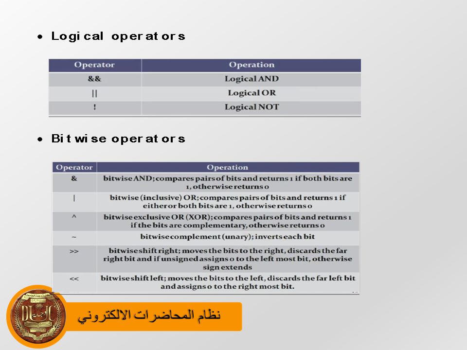


 Ports and Interfacing>")


