Download presentation
Presentation is loading. Please wait.

1
SMJE 2103 Overvoltage, Electrical Insulation and Protection Devices

2
Topics Discussion Overvoltage -External overvoltage -Internal overvoltage -Temporary overvoltage Electrical Insulation -Conduction and breakdown in dielectric -Materials -Damage and failure mechanisms Protection Devices

3
Overvoltage Main interruption to the generated power signal. Causes: lightning and switching surges. Consequences: damage on equipment and load.

4
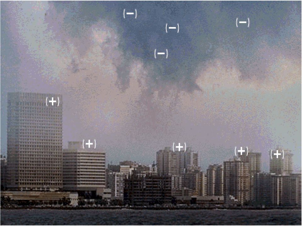
Overvoltage -External- Generated by atmospheric disturbances. Lightning is the most common and the most severe. Lightning is produced by nature to maintain a dynamic balance between the positive charged and negative in ionosphere and earth respectively. The total potential difference between the two main charge centers may very from 100 to 1000MW. The height of the thundercloud dipole above earth may reach 5 km in tropical regions.

5
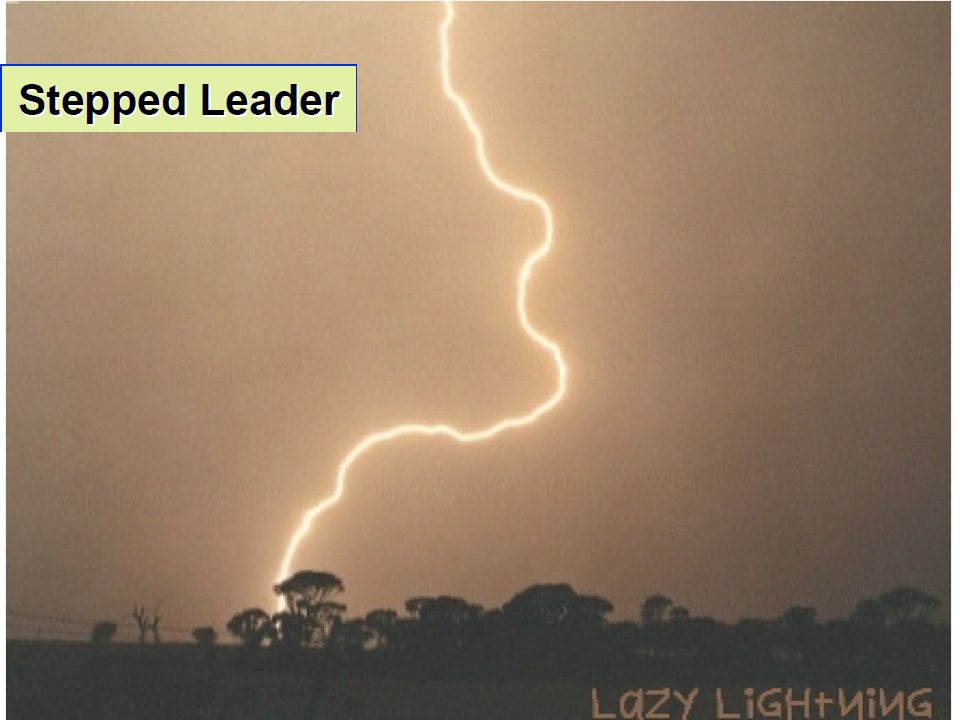
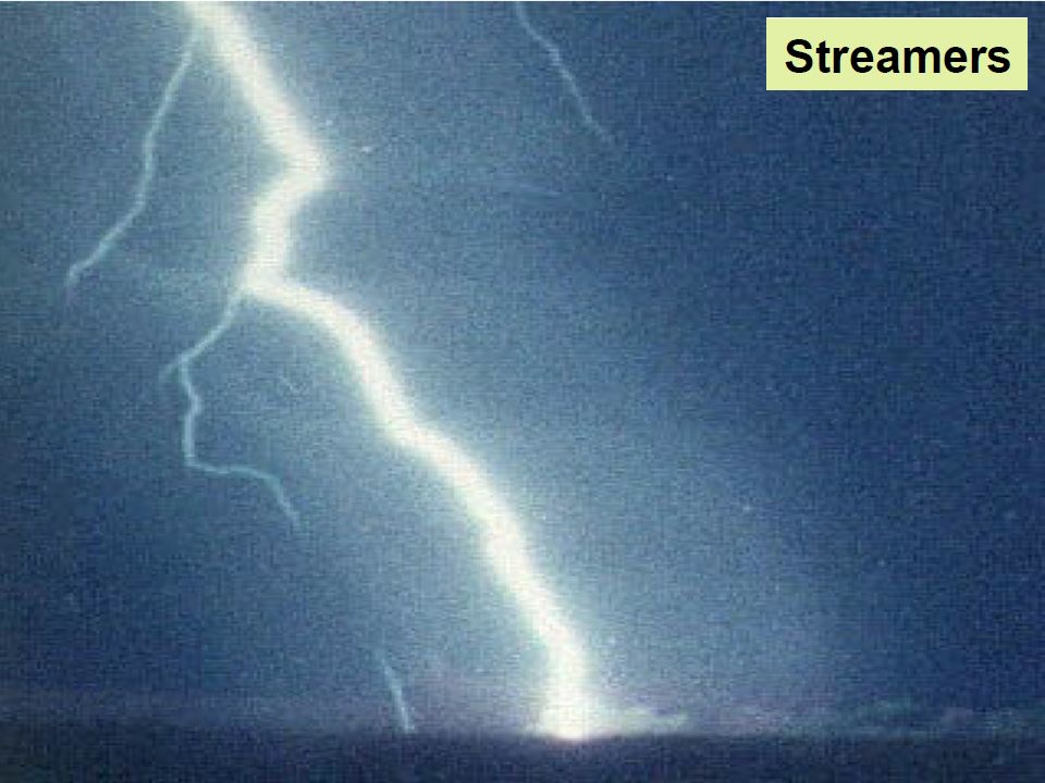
Lightning Phenomenon

6
Facts about Lightning A strike can average 100 million volts of electricity. Current of up to 100,000 A Can generate 54,000 o F Lightning strikes somewhere of the Earth every second. Kills hundreds of people every year.

10
Lightning Voltage Surges The most severe lightning strikes a phase conductor. It produces the highest overvoltage for a given stroke current. The lightning current magnitudes is rarely less than 10kA. For typical overhead line surge impedance Z o of 300Ω, the lightning surge voltage will have 1500 kV. Lightning is always a major source of damage to power system where equipment insulation may break down, under the resulting overvoltage and subsequent high – energy discharge.

11
Lightning Voltage Surges

12
Overvoltage -Internal- Switching overvoltage. It become governing factor in the design of insulation for HV system. One of the events that would initiate a switching surge in a power network is a switching operations. The operations can be classified as follows: 1.Energization of transmission lines and cable. 2.Reenergization of a line. 3.Load rejection. 4.Switching on and off equipment. 5.Fault initiation and clearing.

13
1.Line energization. 2.Reclosing (energization of a line with trapped charges). 3.Low voltage side energization of a line. 4.Energization a line terminated by an unloaded transformer. 5.Load rejection at the receiving end of a line 6.Load rejection at the receiving end of a line followed by line dropping at the sending end Overvoltage - Some important switching operations which can lead to switching surges-

14
7.Interrupting lines at no- load (line dropping). 8.Switching of transformers at no-load. 9.Switching reactor loaded transformers. 10.Switching high voltage reactors 11.Switching at intermediate substations. 12.Initiation of a single-phase to earth fault without a switching operation. Overvoltage -Some important switching operations which can lead to switching surges-

15
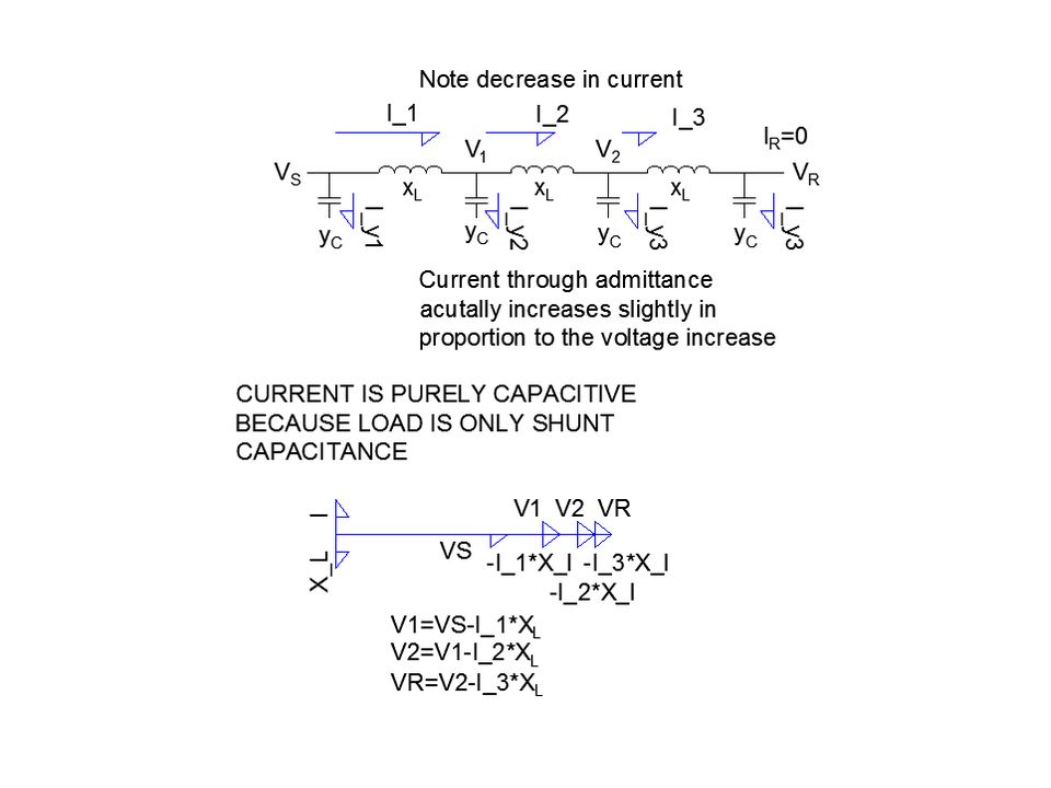
Overvoltage -Energization of an Unloaded Transmission Line-

16
Temporary Overvoltage (sustained overvoltage). This voltage is differ from transient switching overvoltage in that they last for longer duration, typically from a few cycles to a few seconds. The classification of temporary overvoltage as distinct from transient switching overvoltage is due mainly to the fact the responses of power network insulation and surge arresters to their wave shapes are different. Overvoltage -Internal-

17
Events leading to the generation of temporary overvoltage; 1.Load rejection When a transmission line or a large inductive load that is fed from a power station is suddenly switched off, the generator will speed up and the bus bar voltage will rise. 2. Ferranti Effect. When current drawn by the distributed capacitance of the line is greater than in the load at receiving end with no load. So, voltage drop keeps on increasing towards the end of the line then, the receiving end voltage tends to get larger than applied voltage. 3. Ground Fault. In the case of a line-to-ground fault, systems with neutrals isolated or grounded through high impedance may develop overvoltage on healthy phases higher than normal line-to-line voltages Overvoltage -Internal-

19
Electrical Insulation failure The electrical insulation is stressed by several factors; 1.Dielectric 2.Thermal 3.Mechanical 4.Chemical 5.Radiations These factors can produce short and/or long term degradation

20
Electrical Insulation The electrical ensures current flows only along the conductors and NOT between individual conductors or between them to ground. A week insulation may produce: Current leak with local heating up to melting and possibly fire. Progressive damage of the leakage path up to a short circuit. Unbalance of circulating current (with magnetic field distortion). Autotransformer effect with reduction of magnetic field Incorrect functioning of protections
. Autotransformer effect with reduction of magnetic field Incorrect functioning of protections.")
21
Electrical Insulation failure Environmental conditions such as temperature, humidity, pressure can modify the dielectric properties of an electrical system. The failure is due to unsufficient properties or degradation under specific environmental condition.

22
In radiation, failure of a dielectric insulation is due to loss of mechanical properties or the evolution of gases inside the materials. Electrical Insulation failure

23
Conduction in dielectric A non-conducting material, in which macroscopic current are mainly due to the displacement current. When the electric field is high enough a dielectric may suddenly loose its property of non-conduction, permanently or temporarily, showing an electrical breakdown.

24
It consist in the abrupt rise of electrical current under the effect of an electric field. Its causes depend on the medium, the geometry and the type and amplitude of the electrical field. Breakdown in dielectric

25
An analogy

26
Material -Breakdown in Gas- In a gas free charge under a sufficiently high force can produce ionization and avalanche breakdown by hitting other atoms.

27
Insulating liquids in accelerator components are for example in fast magnets pulsers for voltage above 30-50 kV. Also in transformer, capacitor, high voltage switches and circuit breakers. Material -Breakdown in Liquids-

28
Same phenomena as breakdown in gas with consideration of cleanness of insulating materials. Material -Breakdown in Vacuum-

29
Material -Breakdown in Solids-

30
Material -Solid Dielectric-

31
Failure Mechanisms Type of damage and failure mechanisms; 1.Partial discharges. 2.Corona. 3.Electrical treeing 4.Electrical tracking

32
Interfaces air/dielectric such as air bubbles and de-laminations, represent volumes with; 1.Lower dielectric strength 2.Concentration of electric field Failure Mechanisms -partial discharges-

33
In a gas and non uniform electric field, when the breakdown field is exceeded we can have local ionization and discharges. The compounds formed during the discharges and the bombardment of ions can degrade nearly insulating materials. Failure Mechanisms -corona-

35
In case of diverging electrical field (like in HV cable or geometries with sharp edges, point like- electrodes). We can observe a progressive evolution of a conducting path. Failure Mechanisms -electrical treeing-

36
Progressive creation of a conductive path along a surface, due to un-sufficient distance between electrodes with respect to material properties of the surface and to environmental condition. Failure Mechanisms -electrical tracking-

37
Protection Devices Four main features of lightning protection; 1)Air terminal 2)Conductors 3)Ground termination 4)Surge protection
Air terminal 2)Conductors 3)Ground termination 4)Surge protection")
38
Indoor Bonding

39
Indoor Grounding

40
Surge Protection for Power

41
Lightning Protection for Telecommunication Tower

42
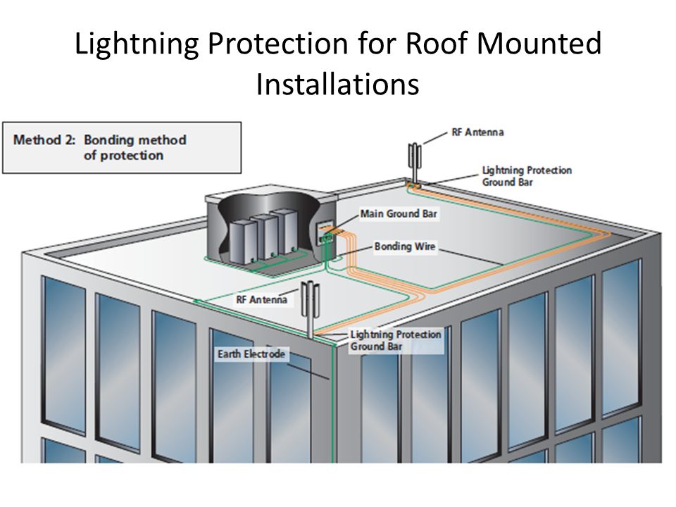
Lightning Protection for Roof Mounted Installations

Similar presentations


 shielding the overhead lines.>")


