Download presentation
Presentation is loading. Please wait.

2
ACCELEROMETER TRANSMITTER- BLOCK DIAGRAM RECEIVER- BLOCK DIAGRAM COMPONENTS DESCRIPTION- ENCODER TRANSMITTER RECEIVER OPTICAL SENSOR

3
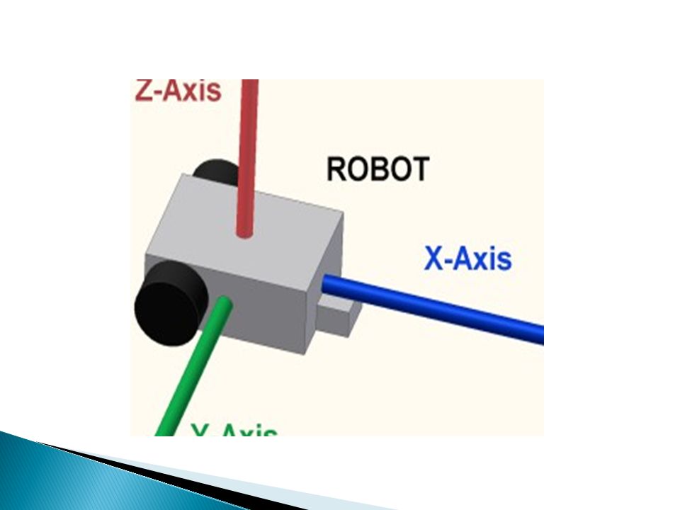
An accelerometer is a device that measures proper acceleration, also called the four-acceleration. For example, an accelerometer on a rocket accelerating through space will measure the rate of change of the velocity of the rocket relative to any inertial frame of reference

4
Conceptually, an accelerometer behaves as a damped mass on a spring. When the accelerometer experiences an acceleration, the mass is displaced to the point that the spring is able to accelerate the mass at the same rate as the casing. The displacement is then measured to give the acceleration. Accelerometers are very important in the sensor world because they can sense a wide range of motion.

6
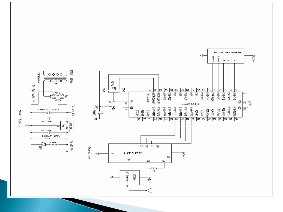
ACCELEROMETER ANALOG TO DIGITAL CONVERTER PIC MICROCONTROLER 16F77 HT12E ENCODER 433MHz TRANSMITTER

7
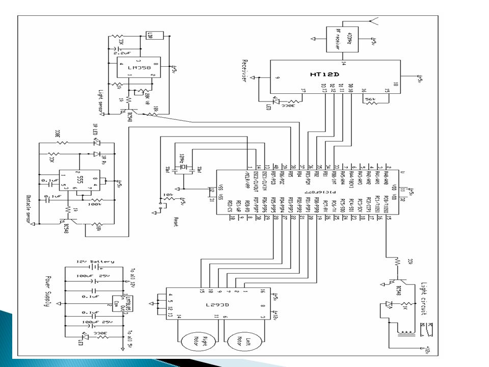
In transmitter circuit we are using accelerometer to sense hand gesture, microcontroller to process the data and FSK transmitter to transmit the data to the Receiver (Robot) In receiver circuit we have FSK receiver, microcontroller and Dc motor driver. The received data is processed by the microcontroller for the specific movement and DC motor drive actuates this data.

9
433MHz RECEIVER DEODER PIC MICROCONTROLER 16F77 H-BRIDGE DRIVER DC MOTOR

11
18 PIN DIP, Operating Voltage : 2.4V ~ 12.0V Low Power and High Noise Immunity, CMOS Technology Low Stand by Current Capable of Decoding 12 bits of Information 8 ~ 12 Address Pins and 0 ~ 4 Data Pins Received Data are checked 2 times, Built in Oscillator needs only 5% resistor VT goes high during a valid transmission Easy Interface with an RF of IR transmission medium Minimal External Components

12
For controlling robot we have used RF transmitting remote. For RF transmission we have used HT12E Encoder IC. The 212 encoders are a series of CMOS LSIs for remote control system applications. They are capable of encoding information which consists of N address bits and 12_N data bits. Each address/ data input can be set to one of the two logic states. The programmed addresses/data are transmitted together with the header bits via an RF or an infrared transmission medium upon receipt of a trigger signal. The capability to select a TE trigger on the HT12E or a DATA trigger on the HT12A further enhances the application flexibility of the 212 series of encoders. The HT12A additionally provides a 38kHz carrier for infrared systems.

13
For RF transmission purposed it is needed to encode the signal generated at computer parallel port with the help visual basic code. For signal encoding purpose we have used HT 12E encoder. HT12 E is 212 encoders are a series of CMOS LSIs for remote control system applications. They are capable of encoding information which consists of N address bits and 12_N data bits. Each address/ data input can be set to one of the two logic states.

14
The infrared intruder sensor is used to sense some unknown person like thief entering in your house without your permission. In the infrared sensor we use IC 555 as a main component. Pin no 4 and pin no 8 is connected to the positive supply. Pin no 1 is connected to the negative voltage. One capacitor is grounded from the pin no 5 for noise cancellation. Output is available on the pin no 3. Sensor is connected to the pin no 2.

15
Light sensor: An LDR is used to sense light. The output voltage of a LRD is amplified by an operational amplifier, and is inputted into the base of transistor.The temperature sensitivity adjusting the gain of an operational amplifier by VR. So in the normal mode when temperature is below 60C the output or LM358 is not sufficient to drive transistor BC 548. When temperature raises above 60C the output of LM358 is about 3V which is sufficient to drive transistor thus microcontroller get positive voltage. DC motor driver: The H-Bridge is used for motor driver. The H-Bridge is widely used in Robotics for driving DC motor in both clockwise and anticlockwise. As shown in the circuit diagram in H Bridge two NPN and two PNP transistors is used.

16
Frequency of 433MHz is used in low power devices. 433 MHz radios are short range, license free communication devices authorized for use in many parts of the world. In some countries, however, voice is not allowed over LPD. They operate in the UHF band from 433.075 MHz to 434.775 MHz with 25 kHz channel spacing, for a total of 69 channels. These devices are frequency modulated(FM) with a maximum legal power output of 10 mW. LPD devices must only be used with the integral and non-removable antenna. LPD was introduced to reduce the burden on the channels over shorter ranges (less than 1 km).
 with a maximum legal power output of 10 mW. LPD devices must only be used with the integral and non-removable antenna. LPD was introduced to reduce the burden on the channels over shorter ranges (less than 1 km)..")
17
THANK YOU

Similar presentations


 GROUP MEMBERS: Anil Kumar Loya ME12B1002 RITESH KUMAR CE12B1019.>")


