Download presentation
Presentation is loading. Please wait.

1
Lecture 11 Luminosity & Colliders Professor Emmanuel Tsesmelis Directorate Office, CERN Department of Physics, University of Oxford ACAS School for Accelerator Physics 2012 Australian Synchrotron, Melbourne November/December 2012

2
Contents – Lecture 11 Accelerators for Particle Physics The Large Hadron Collider Linear Colliders Hadron-Electron Colliders Muon Accelerators Generic Accelerator R&D 2

3
Fermilab Tevatron CERN LHC e+e- Collider The Energy Frontier ep Collider Muon Collider KEK

4
Why Build Colliders? Want to see constituents of matter. Smash matter together and look for the building blocks. Take small pieces of matter: accelerate them to very high energy; crash them into one another E = mc 2 = m 0 c 2 Higher energy produces more massive particles. When particles approach speed of light, they get more massive but not faster.

5
Why Colliders? v~c E = m c 2 P = m v v=0 => Only a tiny fraction of energy converted into mass of new particles (due to energy and momentum conservation) Entire energy converted into the mass of new particles v~c E = m c 2
 Entire energy converted into the mass of new particles v~c E = m c 2.")
6
Key Equation De Broglie Wavelength Planck Constant Momentum De Broglie Wavelength Wave-particle duality; For higher E, probe shorter distances inside matter

7
Introduction - Accelerators Particle accelerators are designed to deliver two parameters to the HEP user Energy Luminosity Measure of collision rate per unit area Event rate for a given event probability (“cross-section”) given by: For a Collider luminosity is given by Require intense beams and small beam sizes at IP
 given by: For a Collider luminosity is given by Require intense beams and small beam sizes at IP")
8
Today’s Accelerators HEP typically uses Colliders Counter-propagating beams collide at one or more IPs. Colliders typically store various particle types Hadrons (protons, ions) Tevatron (p, anti-p), RHIC (p, ions), LHC (p, ions) Leptons (electrons) CESR-c, PEP-II, KEK-B
 Tevatron (p, anti-p), RHIC (p, ions), LHC (p, ions) Leptons (electrons) CESR-c, PEP-II, KEK-B.")
9
9 Collider Characteristics Hadron collider at the frontier of physics huge QCD background not all nucleon energy available in collision Lepton collider for precision physics well defined initial energy for reaction Colliding point like particles Candidate next machine after LHC e + e - collider energy determined by LHC discoveries study in detail the properties of the new physics that the LHC finds p p e+ e- Simulation of HIGGS production e + e – → Z H Z → e + e –, H → bb Simulation of HIGGS LHC

10
10 Circular versus Linear Collider Circular Collider many magnets, few cavities, stored beam higher energy → stronger magnetic field → higher synchrotron radiation losses (E 4 /m 4 R) Linear Collider few magnets, many cavities, single pass beam higher energy → higher accelerating gradient higher luminosity → higher beam power (high bunch repetition) source main linac N S N S accelerating cavities
 Linear Collider few magnets, many cavities, single pass beam higher energy → higher accelerating gradient higher luminosity → higher beam power (high bunch repetition) source main linac N S N S accelerating cavities")
11
Today’s Accelerators Hadron Colliders Protons are composite particles Only ~10% of beam energy available for hard collisions producing new particles. Need O(10 TeV) Collider to probe 1 TeV mass scale. Desired high energy beam requires strong magnets to store and focus beam in reasonable-sized ring. Anti-protons difficult to produce if beam is lost Use proton-proton collisions instead. Demand for ever-higher luminosity has led LHC to choose proton-proton collisions. Many bunches (high bunch frequency). Two separate rings that intersect at select locations.
 Collider to probe 1 TeV mass scale. Desired high energy beam requires strong magnets to store and focus beam in reasonable-sized ring. Anti-protons difficult to produce if beam is lost Use proton-proton collisions instead. Demand for ever-higher luminosity has led LHC to choose proton-proton collisions. Many bunches (high bunch frequency). Two separate rings that intersect at select locations..")
12
Today’s Accelerators Lepton Colliders (e+e-) Synchrotron radiation is the most serious challenge Emitted power in circular machine is For a 1 TeV CM energy Collider in the LHC tunnel with a 1 mA beam, radiated power would be 2 GW Would need to replenish radiated power with RF Remove it from vacuum chamber Approach for high energies is Linear Collider (ILC,CLIC) 12
 Synchrotron radiation is the most serious challenge Emitted power in circular machine is For a 1 TeV CM energy Collider in the LHC tunnel with a 1 mA beam, radiated power would be 2 GW Would need to replenish radiated power with RF Remove it from vacuum chamber Approach for high energies is Linear Collider (ILC,CLIC) 12")
13
CERN Accelerator Complex

14
14 Enter a New Era in Fundamental Science Start-up of the Large Hadron Collider (LHC), one of the largest and truly global scientific projects ever, is the most exciting turning point in particle physics. Exploration of a new energy frontier Proton-proton collisions at E CM = 14 TeV Exploration of a new energy frontier Proton-proton collisions at E CM = 14 TeV LHC ring: 27 km circumference CMS ALICE LHCb ATLAS

15
LHC Lay-out The LHC is a two-ring superconducting proton- proton collider made of eight 3.3 km long arcs separated by 528 m Long Straight Sections. While the arcs are nearly identical, the straight sections are very different. 15

16
LHC Main Bending Cryodipole 8.3 T nominal field 11850 A nominal field

17
The LHC Arcs

18
The LHC Experimental Challenge 18 2808 x 2808 bunches

19
Space Charge Effect (Amman-Ritson Effect) During collision, EM field around one bunch acts upon particles in the other bunch. Deflecting them out of orbit by amount proportional to beam current. Above critical current, most strongly deflected particles become unstable and are lost against vacuum chamber wall.

20
Space Charge & Tune Shift Increases with density of colliding beams. Imposes upper limit on luminosity given by: dQ < few percent for colliding electron beams & factor 10 smaller for proton beams to avoid resonant conditions from guide field errors. For very large dQ, particles encounter optical resonances and are lost. Reduces beam lifetime and increases background in particle detectors. Improve luminosity without increasing dQ by squeezing beams to reduce *. Also by increasing N to limit of beam instability & increase number of bunches.

21
The Mini-beta Principle Small vertical functions at IP using principles of beam optics. Space around IP kept completely free for particle detectors. Small amplitude function at IP results in correspondingly large values at first quadrupoles. Reducing * strongly increases chromaticity induced by quadrupoles nearest to IP. Lower limit of * reached when increase of chromaticity no longer offset by associated reduction in dynamic aperture.

22
The Mini-beta Principle Standard arrangement of focusing magnets around IP

23
The Mini-beta Scheme To achieve considerably higher luminosities place first vertically focusing quadrupole closer to IP. Beams focused earlier and functions prevented from growing to critical values (manageable ). Called mini-beta scheme (minimise *) Smallest reasonable beta function at IP:
. Called mini-beta scheme (minimise *) Smallest reasonable beta function at IP:.")
24
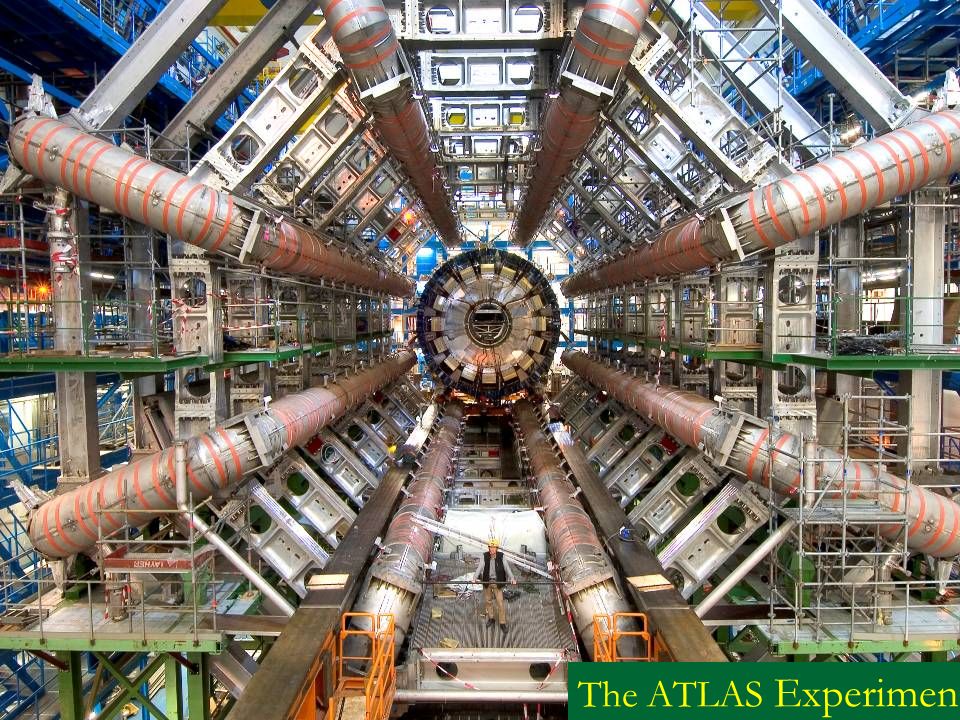
Number of scientists:~3000 Number of institutes:174 Number of countries:38 The ATLAS Experiment

26
The 2011 and 2012 runs … Search for physics within & beyond SM Discovering new particles (Higgs, SUSY…) Making precise measurements of properties of known particles/forces: e.g. B s μ + μ − entered new territory ! …. in 2012 already about 18 fb -1 delivered about 18 fb -1 delivered

27
4 July 2012: CERN press conference “CERN experiments observe particle consistent with long-sought Higgs boson”

28
CMS Heavy Ion Event 28 2.76 TeV per nucleon pair

29
LHC Schedule Assumptions ?, IR 4x ~20-25 fb -1 ~75-100 fb -1 ~350 fb -1, bunch spacing 50 ns Go to design energy, nominal luminosity Injector and LHC Phase-1 upgrade to full design luminosity HL-LHC Phase-2 upgrade, IR, crab cavities? √ s=14 TeV, L=5x10 34 cm -2 s -1, luminosity leveling √ s=14 TeV, L~2x10 34 cm -2 s -1, bunch spacing 25 ns √ s=13~14 TeV, L~1x10 34 cm -2 s -1, bunch spacing 25 ns √ s=7~8 TeV, L=6x10 33 cm -2 s -1, bunch spacing 50 ns LHC startup, √ s = 900 GeV ( Phase-0 ) Study of the properties of the Higgs Boson or Other EW symmetry-breaking mechanism and Physics beyond the Standard Model (BSM)
 Study of the properties of the Higgs Boson or Other EW symmetry-breaking mechanism and Physics beyond the Standard Model (BSM).")
30
Beam Focusing High-Field SC Magnets 13 T, 150 mm aperture quadrupoles for the inner triplet: LHC: 8 T, 70 mm. More focus strength, * as low as 15 cm (55 cm in LHC). In same scheme even * down to 7.5 cm considered. Dipole separators capable of 6-8 T with 150-180 mm aperture (LHC: 1.8 T, 70 mm) 30 Goal: Enable focusing of the beams to *=0.15 m in IP1 and IP5.
. In same scheme even * down to 7.5 cm considered. Dipole separators capable of 6-8 T with mm aperture (LHC: 1.8 T, 70 mm) 30 Goal: Enable focusing of the beams to *=0.15 m in IP1 and IP5..")
31
Thirty Years of SC Accelerators 31

32
High-Energy LHC (HE-LHC) 2-GeV Booster Linac4 SPS+, 1.3 TeV, 2030-33 HE-LHC 2030-33 20T Dipoles Study of New Physics Phenomena Main challenge: High-field Magnets
 2-GeV Booster Linac4 SPS+, 1.3 TeV, HE-LHC T Dipoles Study of New Physics Phenomena Main challenge: High-field Magnets")
33
The Tevatron at FERMILAB 33

34
Tevatron 34 Excellent Performance

35
Young-Kee Kim, ICFA Seminar, CERN, October 3, 201135 We just shut down the Tevatron down at ~2:30 pm, Friday, September 30, 2011; the analysis will continue for several years The Tevatron Shut-down at ~2:30 pm on 30/9/2011 After 28 years of operations.

36
A Generic Linear Collider 30-40 km The machine which will complement and extend the LHC best, and is closest to be realized, is a Linear e+e- Collider.

37
International Linear Collider Baseline Design 250 250 Gev e+ e- Linear Collider Energy 250 GeV x 250 GeV # of RF units 560 # of cryomodules 1680 # of 9-cell cavities 14560 2 Detectors push-pull peak luminosity 2 10 34 5 Hz rep rate, 1000 -> 6000 bunches IP : x 350 – 620 nm; y 3.5 – 9.0 nm Total power ~230 MW Accelerating Gradient 31.5 MeV/m

38
Global Effort on ILC R&D First world-wide coordinated effort under ICFA for R&D, with strengths in all regions Cryomodule Test KEK Yield of 1.3 GHz cavities as a function of gradient. Present yield >35MV is 56%

39
CLIC Conceptual Design Site independent feasibility study aiming at the development of the technologies needed to extend e+ / e- linear colliders into the multi- TeV energy range. E cm range complementary to that of the LHC & ILC E cm = 0.5 – 3 TeV L > few 10 34 cm -2 s -1 with low machine-induced background Minimise power consumption and costs

40
Basic Features High acceleration gradient: > 100 MV/m “Compact” collider – total length < 50 km at 3 TeV Normal conducting acceleration structures at high frequency Novel Two-Beam Acceleration Scheme Cost effective, reliable, efficient Simple tunnel, no active elements Modular, easy energy upgrade in stages CLIC TUNNEL CROSS-SECTION 4.5 m diameter QUAD POWER EXTRACTION STRUCTURE BPM ACCELERATING STRUCTURES Drive beam - 95 A, 240 ns from 2.4 GeV to 240 MeV Main beam – 1 A, 156 ns from 9 GeV to 1.5 TeV 100 MV/m 12 GHz – 64 MW

41
Proposed CLIC Lay-outs 41 Centre-of-mass energy 500 GeVCentre-of-mass energy 3 TeV CLIC footprints near CERN

42
CLIC Parameters

43
Standard tunnel with modules Standard tunnel with modules (Courtesy John Osborne) Tunnel Integration 43
 Tunnel Integration 43")
44
For CLIC & ILC - Similar World Projects: Channel Tunnel 7.6mØ 4.8m Ø 50Km 44

45
Other Technological Challenges The final focusing quadruple should be stabilized to 0.15 nm for frequencies about 4 Hz 45

46
Other Technological Challenges 0.15 nm, small as a H 2 0 molecule ! 46

47
LHeC options: RR and LR RR LHeC: new ring in LHC tunnel, with bypasses around experiments RR LHeC e-/e+ injector 10 GeV, 10 min. filling time LR LHeC: recirculating linac with energy recovery, or straight linac 47 QCD, Leptoquarks? Would be successor of HERA at higher centre-of-mass energy

48
LHeC Design Parameters electron beamRRLRLR * e- energy at IP[GeV]60 140 luminosity [10 32 cm -2 s -1 ]17100.44 polarization [%]4090 bunch population [10 9 ]262.01.6 e- bunch length [mm]100.3 bunch interval [ns]2550 transv. emit. x,y [mm] 0.58, 0.290.050.1 rms IP beam size x,y [ m] 30, 1677 e- IP beta funct. * x,y [m] 0.18, 0.100.120.14 full crossing angle [mrad]0.9300 geometric reduction H hg 0.770.910.94 repetition rate [Hz]N/A 10 beam pulse length [ms]N/A 5 ER efficiencyN/A94%N/A average current [mA]1316.65.4 tot. wall plug power[MW]100 proton beamRRLR bunch pop. [10 11 ]1.7 tr.emit. x,y [ m] 3.75 spot size x,y [ m] 30, 167 * x,y [m] 1.8,0.50.1 bunch spacing [ns]25 RR= Ring – Ring LR =Linac –Ring 50 ns & N b =1.7x10 11 probably conservative design also for deuterons (new) and lead (exists) *) pulsed, but high energy ERL not impossible
![LHeC Design Parameters electron beamRRLRLR * e- energy at IP[GeV] luminosity [10 32 cm -2 s -1 ] polarization [%]4090 bunch population [10 9 ] e- bunch length [mm]100.3 bunch interval [ns]2550 transv.](http://images.slideplayer.com/34/10194064/slides/slide_48.jpg "emit. x,y [mm] 0.58, rms IP beam size x,y [ m] 30, 1677 e- IP beta funct. * x,y [m] 0.18, full crossing angle [mrad] geometric reduction H hg repetition rate [Hz]N/A 10 beam pulse length [ms]N/A 5 ER efficiencyN/A94%N/A average current [mA] tot. wall plug power[MW]100 proton beamRRLR bunch pop. [10 11 ]1.7 tr.emit. x,y [ m] 3.75 spot size x,y [ m] 30, 167 * x,y [m] 1.8, bunch spacing [ns]25 RR= Ring – Ring LR =Linac –Ring 50 ns & N b =1.7x10 11 probably conservative design also for deuterons (new) and lead (exists) *) pulsed, but high energy ERL not impossible.")
49
ERL Configuration LHC p 1.0 km 2.0 km 10-GeV linac injector dump IP comp. RF e- final focus tune-up dump 0.26 km 0.17 km 0.03 km 0.12 km comp. RF total circumference ~ 8.9 km 10, 30, 50 GeV 20, 40, 60 GeV

50
Physics with Muon Beams Neutrino Sector Decay kinematics well known e µ oscillations give easily detectable wrong-sign µ Energy Frontier Point particle makes full beam energy available for particle production Couples strongly to Higgs sector Muon Collider has almost no synchrotron radiation Narrow energy spread Fits on existing laboratory sites 50

51
Muon Beam Challenges Muons created as tertiary beam (p µ) Low production rate Need target that can tolerate multi-MW beam Large energy spread and transverse phase space Need solenoidal focusing for the low-energy portions of the facility (solenoids focus in both planes simultaneously) Need acceptance cooling High-acceptance acceleration system and decay ring Muons have short lifetime (2.2 µs at rest) Puts premium on rapid beam manipulations Presently untested ionization cooling technique High-gradient RF cavities (in magnetic field) Fast acceleration system Decay electrons give backgrounds in Collider detectors and instrumentation & heat load to magnets 51
 Low production rate Need target that can tolerate multi-MW beam Large energy spread and transverse phase space Need solenoidal focusing for the low-energy portions of the facility (solenoids focus in both planes simultaneously) Need acceptance cooling High-acceptance acceleration system and decay ring Muons have short lifetime (2.2 µs at rest) Puts premium on rapid beam manipulations Presently untested ionization cooling technique High-gradient RF cavities (in magnetic field) Fast acceleration system Decay electrons give backgrounds in Collider detectors and instrumentation & heat load to magnets 51")
52
Neutrino Factory 52 Aim for 10 21 e per year directed towards detector(s)
")
53
Muon Collider 53 e.g. @ FNAL

54
Plasma Accelerators

Similar presentations


 cm -2 s -1 with Beam Power 100 MW (wall plug) Integrated e ± p.>")


