Download presentation
Presentation is loading. Please wait.

1
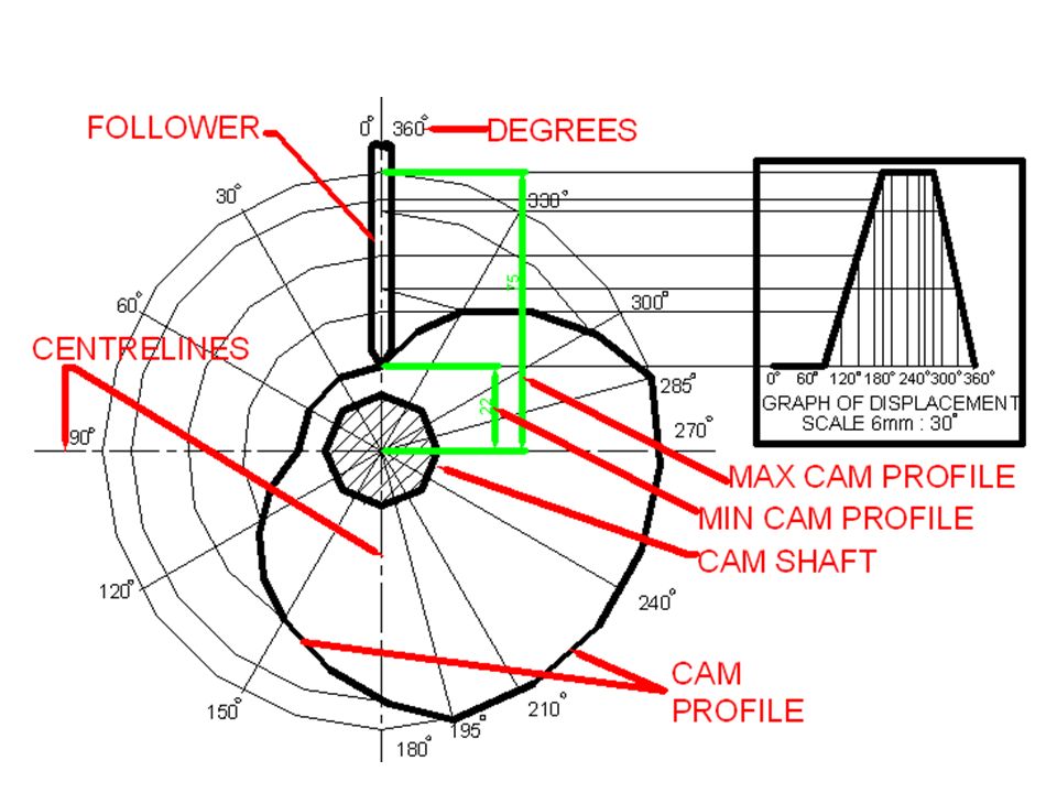
CAM PROFILE -Converts linear motion into rotary motion ` TERMS -GRAPH OF DISPLACEMENT -SCALE -CAM SHAFT/SPINDLE -FOLLOWER -DIRECTION -MINIMUM CAM PROFILE -MAXIMUM CAM PROFILE -LOCUS

2
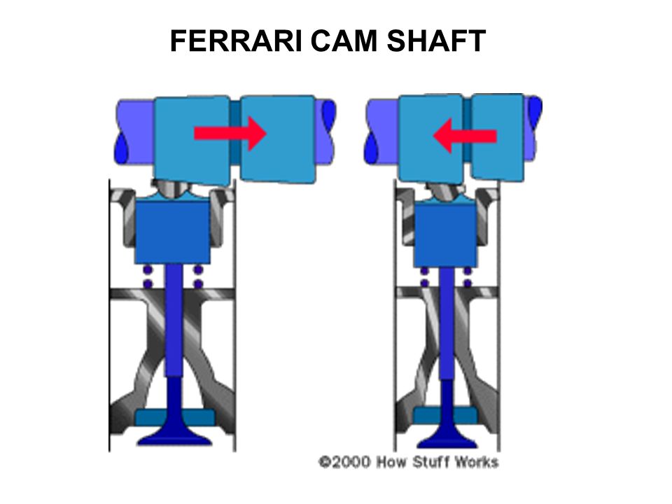
FERRARI CAM SHAFT

4
ENGINE CAM

5
DRUM CAM & FLAT FOLLOWER

6
CAR ENGINE CAM

7
WEDGE-ENDED & FLAT FOLLOWER

8
FLAT & ROLLER-ENDED FOLLOWER

9
ROCKER PUMP MECHANISMS

10
1. GRAPH OF DISPLACEMENT - determines the movement of the follower 1.1. SCALE - Determines the width of the graph. This is a horizontal scale. The vertical scale is always SCALE 1:1 1.2. RISE MOVEMENT - Moving up the graph 1.3. FALL MOVEMENT -Moving down the graph 1.4. DWELL MOVEMENT - No rise or fall movement, just horizontal shifting

12
MINIMUM & MAXIMUM CAM PROFILES-WEDGE MINIMUM CAM PROFILE Minimum distance from the centre of the cam shaft to the profile. MAXIMUM CAM PROFILE Maximum distance from the centre of the cam shaft to the profile.

13
MINIMUM & MAXIMUM CAM PROFILES- ROLLER MINIMUM CAM PROFILE Minimum distance from the centre of the cam shaft to the profile. MAXIMUM CAM PROFILE Maximum distance from the centre of the cam shaft to the profile.

14
1.Draw graph of displacement 2.Project all points to vertical centreline 3.Construct all degree generators 4.Project off the vertical centreline onto the degree generators

15
5. Draw circles at all the degree generator points, to represent the position of the follower for that movement. These circles must be the same diameter as the follower. 6. Label the drawing.

16
7. Using a flexi-curve or a french curve, join all the tangents of the degree generator circles to give a smooth, clear locus. This locus is called the CAM PROFILE. 8. Insert the direction[ clockwise / anti-clockwise]

Similar presentations


 or oscillatory motion to rotary motion (rarely) For high speed applications.>")


