Download presentation
Presentation is loading. Please wait.

1
Multi-carrier Handover Method IEEE 802.16 Presentation Submission Template (Rev. 9) Document Number: IEEE C802.16m-08/1007 Date Submitted: 2008-09-05 Source: Yih-Guang Jan, Yang-Han Lee, E-mail: yihjan@yahoo.com Ming-Hsueh Chuang, Hsien-Wei Tseng, Wei-Chieh Tseng, Po-Jung Lin, Ting-Chien Wang Tamkang University (TKU) Shiann-Tsong SheuE-mail: stsheu@ce.ncu.edu.tw National Central University (NCU) Whai-En Chen E-mail: wechen@niu.edu.tw National Ilan University (NIU) Venue: PHY: Multi-Carrier Operation; in response to the TGm Call for Contributions and Comments 802.16m-08/033 for Session 57 Base Contribution: N/A Purpose: Propose a Multi-carrier Handover method Notice: This document does not represent the agreed views of the IEEE 802.16 Working Group or any of its subgroups. It represents only the views of the participants listed in the “Source(s)” field above. It is offered as a basis for discussion. It is not binding on the contributor(s), who reserve(s) the right to add, amend or withdraw material contained herein. Release: The contributor grants a free, irrevocable license to the IEEE to incorporate material contained in this contribution, and any modifications thereof, in the creation of an IEEE Standards publication; to copyright in the IEEE’s name any IEEE Standards publication even though it may include portions of this contribution; and at the IEEE’s sole discretion to permit others to reproduce in whole or in part the resulting IEEE Standards publication. The contributor also acknowledges and accepts that this contribution may be made public by IEEE 802.16. Patent Policy: The contributor is familiar with the IEEE-SA Patent Policy and Procedures: and.http://standards.ieee.org/guides/bylaws/sect6-7.html#6http://standards.ieee.org/guides/opman/sect6.html#6.3 Further information is located at and.http://standards.ieee.org/board/pat/pat-material.htmlhttp://standards.ieee.org/board/pat
 Document Number: IEEE C802.16m-08/1007 Date Submitted: Source: Yih-Guang Jan, Yang-Han Lee, Ming-Hsueh Chuang, Hsien-Wei Tseng, Wei-Chieh Tseng, Po-Jung Lin, Ting-Chien Wang Tamkang University (TKU) Shiann-Tsong Sheu National Central University (NCU) Whai-En Chen National Ilan University (NIU) Venue: PHY: Multi-Carrier Operation; in response to the TGm Call for Contributions and Comments m-08/033 for Session 57 Base Contribution: N/A Purpose: Propose a Multi-carrier Handover method Notice: This document does not represent the agreed views of the IEEE Working Group or any of its subgroups. It represents only the views of the participants listed in the Source(s) field above. It is offered as a basis for discussion. It is not binding on the contributor(s), who reserve(s) the right to add, amend or withdraw material contained herein. Release: The contributor grants a free, irrevocable license to the IEEE to incorporate material contained in this contribution, and any modifications thereof, in the creation of an IEEE Standards publication; to copyright in the IEEE’s name any IEEE Standards publication even though it may include portions of this contribution; and at the IEEE’s sole discretion to permit others to reproduce in whole or in part the resulting IEEE Standards publication. The contributor also acknowledges and accepts that this contribution may be made public by IEEE Patent Policy: The contributor is familiar with the IEEE-SA Patent Policy and Procedures: and. Further information is located at and.")
2
Introduction (1/3) With the development of new technologies, mobile communication services have been actively developed into the wireless network and also has moved into the study and development of high speed mobile station services. IEEE 802.16m is the standard of next generation wireless communication system, it has the advantages of wide bandwidth, high transmission speed and wide coverage areas etc. Although it has many advantages in wireless communications, it has accompanied with it various kind of interferences, including the interferences between mobile to mobile, mobile to base station and base station to base station.

3
Introduction (2/3) When mobile moves the distance between the mobile station and the base station changes; when the communication distance changes the communication channel also suffers various interferences, the mobile station received signal strength will consequently be varied. As the mobile station moves further away from the base station its received signal strength will be becoming weaker it needs to resort to handover (HO) process to maintain a good quality of service and to maintain the data can be transmitted normally. Consequently in the consideration of the overall wireless communication system the handover process plays the vital role in the wireless communication.
 process to maintain a good quality of service and to maintain the data can be transmitted normally. Consequently in the consideration of the overall wireless communication system the handover process plays the vital role in the wireless communication..")
4
Introduction (3/3) In this contribution we will be based on the standard of 802.16m system to propose the multi-carrier handover process so that this handover mechanism can be selected and implemented into the 802.16m system. In the discussion of multi-carrier handover mechanism we assume in our discussion that the system synchronization has completed therefore the synchronization process will not be discussed in this contribution. We will also in this contribution to discuss the effect of changing the hysteresis on the system drop rate and its resulting handover rate when the hysteresis changes with the mobile speed.

5
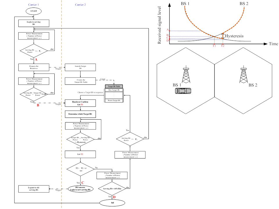
Illustrative Figures of Multi-carrier Handover As shown in the left figure is to illustrate the mobile station signal strength as MS moves away from BS1 and towards BS2. In the following we will discuss in detail the handover process for the following two cases. –Case 1: Multi-carrier handover process with illustrative figures. –Case 2: Failure of multi-carrier handover process with illustrative figures.

6
Case 1 : Illustrative Figures of Multi- carrier Handover (1/3) When MS moves from BS 1 to Position 1 –Carrier 1 At point A as shown in the figure the MS received signal strength from BS 1 becomes weaker and it initiates the Carrier 1 to trigger Carrier 2 to ready for handover process. –Carrier 2 When it receives the trigger signal from Carrier 1, it executes the searching process to find the received signal strengths from the MS of those neighboring base stations to determine which BS will be used in the handover process.

7
Case 1 : Illustrative Figures of Multi- carrier Handover (2/3) When MS moves to around the location that has equal distances from two base stations –Carrier 1 MS receives the same signal strengths from BS 1 and BS 2 as shown at Point B, it triggers Carrier 2 to execute the handover. –Carrier 2 Carrier 2 receives the trigger signal from BS 1, it starts the execution of handover process, Carrier 2 selects the target Target BS from its searching process as discussed in the previous slide.

8
Case 1 : Illustrative Figures of Multi- carrier Handover (3/3) As MS is located at the marked position it has the signal strength at point C –Carrier 1 After Carrier 2 completes the handover process, Carrier 1 disconnects its connection with BS1. –Carrier 2 MS has reached the hysteresis level it determines to handover to BS 2.

9
Case 2: Illustrative Figures of the Failure of Multi-carrier Handover As MS is located at the new location it has signal strength at location D –Carrier 1 As MS receives signal strength from BS 1 is below its critical value and also Carrier 2 fails in its handover process MS will be dropped from BS 1. –Carrier 2 If it does not complete the handover process and it still does not successfully connect with target BS2, it fails the handover process and the MS will be disconnect from BS1.

10
System Flow Chart of Multi-Carrier Handover (1/2) We summarize in the following figure the system flow chart for multi- carrier handover and it will be considered and accepted as the handover routine in 802.16m system. Multi-carrier handover system flow chart: As MS moves into the system it starts to transmit data to the serving BS. When the MS receives equal signal strengths from its serving BS and its neighboring BS, it starts the handover process and identifies this time point as T1, it then determines its target BS. When the received target BS signal strength is larger than the hysteresis value of the serving BS, it identifies this time instant as T2.

11
System Flow Chart of Multi-Carrier Handover (2/2) As the time difference of T2 and T1 is less then a to be determined constant χ seconds, it will be claimed as a successful handover, otherwise when the time difference is larger than χ seconds it will determine whether the MS receives signal strength is larger than the BS signal sensitivity, if it is, then it continues to proceed on the handover process, otherwise it fails the MS handover, the MS is dropped out the MS will re-start its network entering process and to proceed on the registration process. In this contribution in the simulation of handover process we take the time difference of χ as 1 second.

13
Analysis of the Effect of Hysteresis on Handover (1/4) In the process of handover when it increases the hysteresis it will keep longer connection time of the MS with the serving BS before it terminates connection with serving BS and handover to the target BS that it decrease the unnecessary handover or the ping-pong effect. However due to its low receiving receiver signal strength with the serving BS it tends to drop more easily when it makes long connection with the serving BS. In the following we will consider the effect of hysteresis on the system drop rate and handover rate when the hysteresis value varies with the mobile speed. As shown in the following figures, when the hysteresis increases, the number of handover decreases but the system drop rate is increasing.

14
Analysis of the Effect of Hysteresis on Handover (2/4)
")
15
Analysis of the Effect of Hysteresis on Handover (3/4) Average Drop Rate (%) Hysteresis Values (dB)
 Average Drop Rate (%) Hysteresis Values (dB)")
16
Analysis of the The Effect of Hysteresis on Handover (4/4) Hysteresis Values (dB) Normalized Handover Rate (%)
 Hysteresis Values (dB) Normalized Handover Rate (%)")
17
Conclusion (1/3) In the analysis of the drop and handover rates from simulation results with the hysteresis value varies with MS speed we have the following conclusions: –When the system drops rate keeps below 20% the hysteresis values for MS speeds at 350 km/hr, 120 km/hr and 60 km/hr will be 5 dB, 7 db and 9 dB respectively to have the minimum number of handover and the system load will be minimized. –When the system drops rate is maintained below 15% the hysteresis values for 120 km/hr and 60 km/hr speeds will be 6 dB and 8 dB respectively. –And so on, when the drop rate is kept below 10% the hysteresis values for 120 km/hr and 60 km/hr will be 6 db and 8 db respectively.

18
Conclusion (2/3)
")
19
Conclusion (3/3) We also found that when the hysteresis changes from 5 dB to 7 dB the number of handover has declined to the largest extent and if we do not take the system drop rate into consideration the system will have the highest efficiency when the hysteresis is selected at 7 dB.
 We also found that when the hysteresis changes from 5 dB to 7 dB the number of handover has declined to the largest extent and if we do not take the system drop rate into consideration the system will have the highest efficiency when the hysteresis is selected at 7 dB.")
20
Text Proposal ===================Start of Proposed Text==================== 19 Support for Multi-carrier 19.x Multi-carrier Handover Method The Multi-carrier handover mechanism has the flow chart as shown in the following figure, where in the figure the points A, B, C and D represent the various received signal strengths during the handover process:

21
===================End of Proposed Text===================

Similar presentations
 Document Number: IEEE C802.16m-08/1007r1 Date Submitted: 2008-09-16.>")
 IEEE 802.16 Presentation Submission Template (Rev. 9) Document Number: IEEE S802.16m-09/1742.>")
 Document Number: IEEE S802.16m-08/099 Date Submitted:>")
 Document Number: IEEE C802.16gman-10/0018.>")
 IEEE 802.16 Presentation Submission Template (Rev. 9) Document Number: IEEE C80216m-10_0765 Date Submitted:>")
 Document Number: IEEE S802.16m-08/981r1 Date Submitted: 2008-09-12 Source:>")
 Document Number: IEEE C802.16ppc-10/0008 Date Submitted: 2010-04-07.>")

 Document Number: IEEE C80216m-09_0475r1 Date.>")
 Document Number: IEEE C802.16m-09/0178 Date Submitted: 2009-1-5 Source:>")
 Document Number: IEEE C802.16m-08/588 Date Submitted: 2008-07-xx.>")
 Document Number: IEEE C80216m-09_0800 Date Submitted: 2009-04-24 Source: Raunak.>")
 Document Number: IEEE C80216m-10_1249r1.>")
 Document Number: IEEE C802.16m-09/0762r2.>")


 Document Number: IEEE C802.16m-08/1273 Date Submitted:>")
 Document Number: IEEE C802.16m-08/1176r1.>")

 Document Number: IEEE S802.16n-11/0074 Date Submitted:>")