Download presentation
Presentation is loading. Please wait.

1
WIND TURBINE ENGINEERING ANALYSIS AND DESIGN Jean-Jacques Chattot University of California Davis OUTLINE Challenges in Wind Turbine Flows The Analysis Problem and Simulation Tools The Vortex Model for Analysis and Design The Hybrid Approach Conclusion VESTAS Wednesday, March 19, 2008

2
CHALLENGES IN WIND TURBINE FLOW ANALYSIS AND DESIGN Vortex Structure - importance of maintaining vortex structure 10-20 D - free wake vs. prescribed wake models - nonlinear effects on swept tips and winglets High Incidence on Blades - separated flows and 3-D viscous effects Unsteady Effects - yaw, tower interaction, earth boundary layer Blade Flexibility

3
CHALLENGES IN WIND TURBINE FLOW ANALYSIS

4
THE ANALYSIS PROBLEM AND SIMULATION TOOLS Actuator Disk Theory (1-D Flow) Empirical Dynamic Models (Aeroelasticity) Vortex Models - prescribed wake + equilibrium condition - free wake - applied to design of blades for maximum power at given thrust on tower (including sweep and winglets) Euler/Navier-Stokes Codes - 10 M grid points, still dissipates wake - not practical for design
 Empirical Dynamic Models (Aeroelasticity) Vortex Models - prescribed wake + equilibrium condition - free wake - applied to design of blades for maximum power at given thrust on tower (including sweep and winglets) Euler/Navier-Stokes Codes - 10 M grid points, still dissipates wake - not practical for design")
5
REVIEW OF VORTEX MODEL Goldstein Model Simplified Treatment of Wake -Rigid Wake Model -“Ultimate Wake” Equilibrium Condition -Base Helix Geometry Used for Steady and Unsteady Flows Application of Biot-Savart Law Blade Element Flow Conditions 2-D Viscous Polar

6
GOLDSTEIN MODEL Vortex sheet constructed as perfect helix with variable pitch

7
SIMPLIFIED TREATMENT OF WAKE - No stream tube expansion, no sheet edge roll-up (second-order effects) -Vortex sheet constructed as perfect helix called the “base helix” corresponding to zero yaw
 -Vortex sheet constructed as perfect helix called the base helix corresponding to zero yaw")
8
“ULTIMATE WAKE” EQUILIBRIUM CONDITION Induced axial velocity from average power:

9
BASE HELIX GEOMETRY USED FOR STEADY AND UNSTEADY FLOWS Vorticity is convected along the base helix, not the displaced helix, a first-order approximation

10
RESULTS: STEADY FLOW Power output comparison

11
RESULTS: YAWED FLOW Time-averaged power versus velocity at different yaw angles =5 deg =10 deg =20 deg=30 deg

12
TOWER INTERFERENCE MODEL Simplified Model NREL Root Flap Bending Moment Comparison - Effect of Incoming Velocity V=5, 8 and 10 m/s - Effect of Yaw yaw=5, 10 and 20 deg

13
“UPWIND” CONFIGURATION

14
NREL ROOT FLAP BENDING MOMENT COMPARISON V=5 m/s, yaw=20 deg

15
HYBRID APPROACH Use Best Capabilities of Physical Models - Navier-Stokes for near-field viscous flow - Vortex model for far-field inviscid wake Couple Navier-Stokes with Vortex Model - improved efficiency - improved accuracy

16
Navier-Stokes Vortex Method Vortex Filament Biot-Savart Law (discrete) Boundary of Navier-Stokes Zone Converged for … Bound Vortex Fig. 1 Coupling Methodology HYBRID METHODOLOGY

17
RECENT PUBLICATIONS S. H. Schmitz, J.-J. Chattot, “A coupled Navier-Stokes/Vortex- Panel solver for the numerical analysis of wind turbines”, Computers and Fluids, Special Issue, 35: 742-745 (2006). S. H. Schmitz, J.-J. Chattot, “A parallelized coupled Navier- Stokes/Vortex-Panel solver”, Journal of Solar Energy Engineering, 127:475-487 (2005). J.-J. Chattot, “Extension of a helicoidal vortex model to account for blade flexibility and tower interference”, Journal of Solar Energy Engineering, 128:455-460 (2006). S. H. Schmitz, J.-J. Chattot, “Characterization of three-dimensional effects for the rotating and parked NREL phase VI wind turbine”, Journal of Solar Energy Engineering, 128:445-454 (2006). J.-J. Chattot, “Helicoidal vortex model for wind turbine aeroelastic simulation”, Computers and Structures, 85:1072-1079 (2007). S. H. Schmitz, J.-J. Chattot, “A method for aerodynamic analysis of wind turbines at peak power”, Journal of Propulsion and Power, 23(1):243-246 (2007). J.-J. Chattot, “Effects of blade tip modifications on wind turbine performance using vortex model”, AIAA 2008-1315 (2006).
. S. H. Schmitz, J.-J. Chattot, A parallelized coupled Navier- Stokes/Vortex-Panel solver , Journal of Solar Energy Engineering, 127: (2005). J.-J. Chattot, Extension of a helicoidal vortex model to account for blade flexibility and tower interference , Journal of Solar Energy Engineering, 128: (2006). S. H. Schmitz, J.-J. Chattot, Characterization of three-dimensional effects for the rotating and parked NREL phase VI wind turbine , Journal of Solar Energy Engineering, 128: (2006). J.-J. Chattot, Helicoidal vortex model for wind turbine aeroelastic simulation , Computers and Structures, 85: (2007). S. H. Schmitz, J.-J. Chattot, A method for aerodynamic analysis of wind turbines at peak power , Journal of Propulsion and Power, 23(1): (2007). J.-J. Chattot, Effects of blade tip modifications on wind turbine performance using vortex model , AIAA (2006)..")
18
CONCLUSIONS Vortex Model: simple, efficient, can be used for design Stand-alone Navier-Stokes: too expensive, dissipates wake, cannot be used for design Hybrid Model: takes best of both models to create most efficient and reliable simulation tool Next Frontier: aeroelasticity and multidisciplinary design

19
APPENDIX A UAE Sequence Q V=8 m/s pitch=18 deg CN at 80%

20
APPENDIX A UAE Sequence Q V=8 m/s pitch=18 deg CT at 80%

21
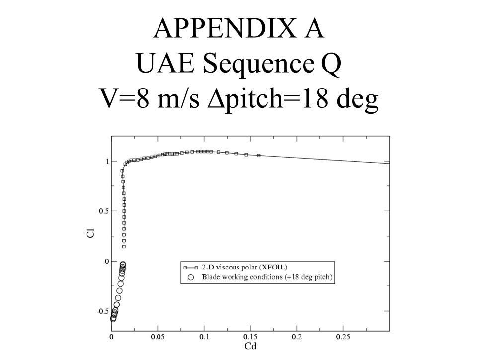
APPENDIX A UAE Sequence Q V=8 m/s pitch=18 deg

23
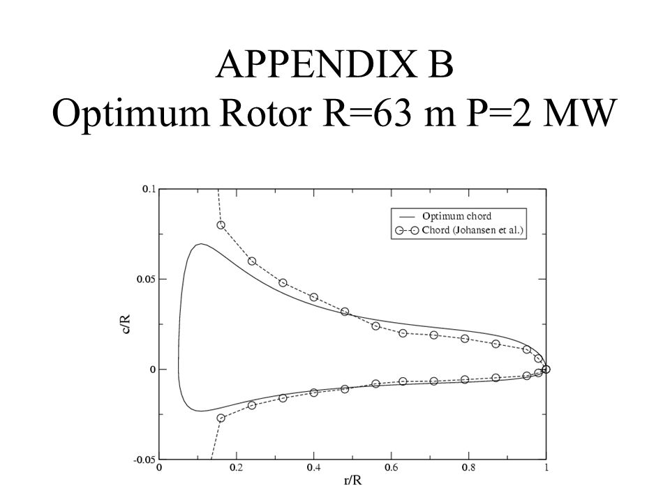
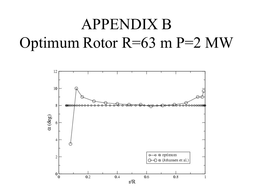
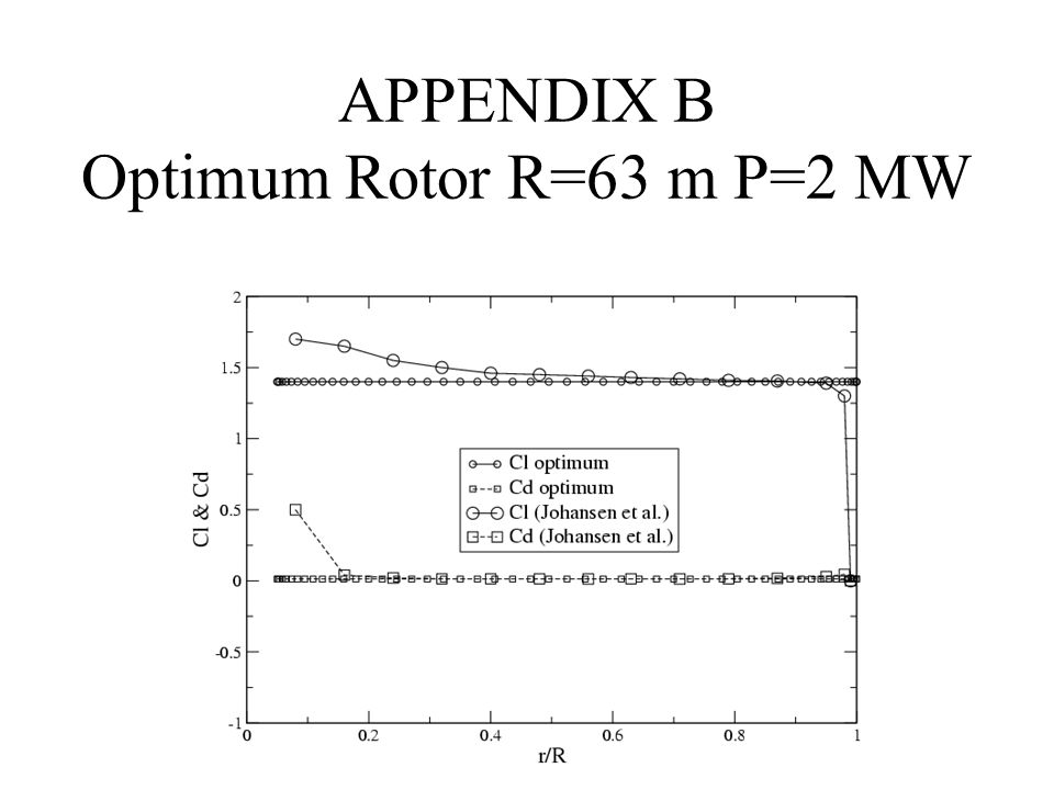
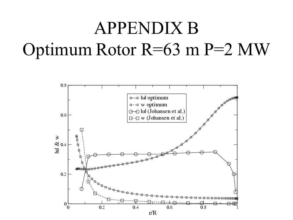
APPENDIX B Optimum Rotor R=63 m P=2 MW

30
APPENDIX C Homogeneous blade; First mode

31
APPENDIX C Homogeneous blade; Second mode

32
APPENDIX C Homogeneous blade; Third mode

33
APPENDIX C Nonhomogeneous blade; M’ distribution

34
APPENDIX C Nonhomog. blade; EIx distribution

35
APPENDIX C Nonhomogeneous blade; First mode

36
APPENDIX C Nonhomogeneous blade; Second mode

37
APPENDIX C Nonhomogeneous blade; Third mode

38
TOWER SHADOW MODEL DOWNWIND CONFIGURATION

Similar presentations


>")


