Download presentation
Presentation is loading. Please wait.

1
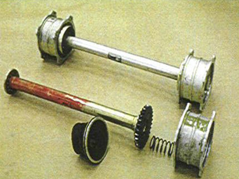
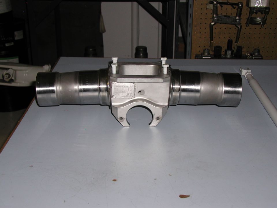
MAIN DRIVE SHAFT The main drive shaft consists of a flanged hollow shaft with flexible splined couplings. This assembly is installed between the freewheeling adapter flange and the transmission input pinion adapter flange. A spring in each coupling assists in centering of drive shaft during operation.

2
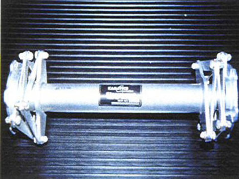
MAIN DRIVE SHAFT

5
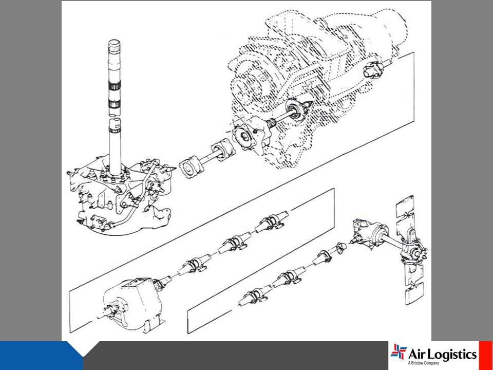
Transmission Viewed from left side

8
DRIVE TRAIN

9
ROTOR BRAKE The rotor brake is attached to the aft coupling of the main drive shaft and used for manually stopping drive train rotation upon shutdown. Engine starts with rotor brake engaged are prohibited. During prestart checks ensure the ROTOR BRAKE handle is Up and Latched. During the shutdown sequence the rotor brake may be applied between 38% and 30% Rotor RPM. Return the handle to the stowed position after main rotor stops.

10
CAUTION AVOID RAPID ENGAGEMENT OF THE ROTOR BRAKE IF HELICOPTER IS ON ICE OR OTHER SLIPPERY OR LOOSE SURFACE TO PREVENT ROTATION OF HELICOPTER. This is an optional item to the basic aircraft and information on its procedures and limitations may be found in the Supple- ments Section of the Flight Manual.

11
ROTOR BRAKE

12
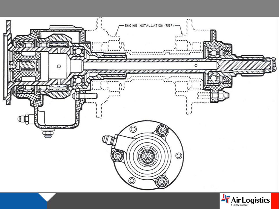
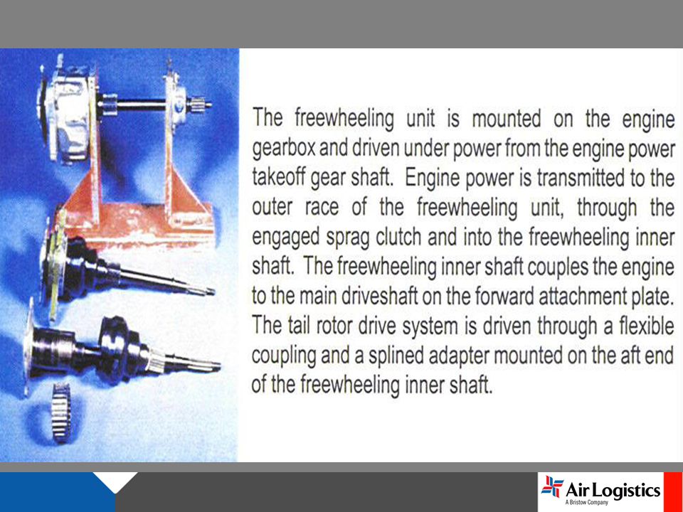
FREEWHEELING ASSEMBLY The freewheeling assembly is mounted on the engine accessory gearbox and its shaft is splined directly to the power takeoff gear shaft. Engine power is transmitted to the outer race of the freewheeling assembly, then through the full- phasing sprag elements of the assembly which couples the engine power to the transmission driveshaft.

13
The forward tail rotor drive short shaft connects through a flexible coupling to a splined adapter on the aft end of the freewheeling shaft that passes through the engine reduction gearbox During autorotation the main rotor drives the inner race shaft assembly. Under this condition, the freewheeling assembly provides a disconnect from the engine so the rotational forces of the main rotor are free to drive the transmission, tail rotor, and all transmission mounted accessories.

14
FREE WHEELING UNIT

17
POWERED AUTOROTATION

18
FREEWHEELING UNIT

19
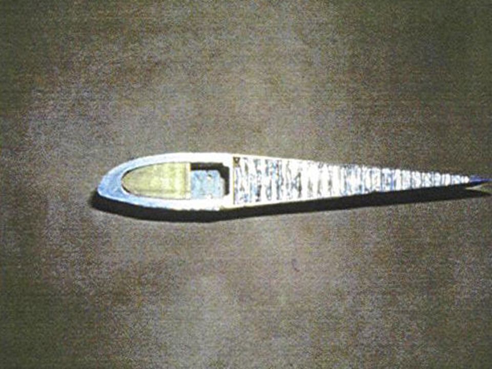
TAIL ROTOR DRIVE SHAFT The tail rotor driveshaft is made up of the following: forward short shaft, the oil cooler fan shaft, the aft short shaft, (5 ea.) identical, interchangeable segments connecting to the tail rotor gearbox. There are seven deep grooved ball bearings supporting these shafts, which require lubricant each 300 flight hrs. Flexible steel disc couplings connect the shaft sections. The forward short shaft and oil cooler fan shaft are made of steel, while the aft short shaft and five segments are constructed of aluminum alloy.

20
FWD / AFT SHORT SHAFT OIL COOLER FAN SHAFT

21
DRIVE SHAFT SEGMENTS TAILROTOR GEARBOX

22
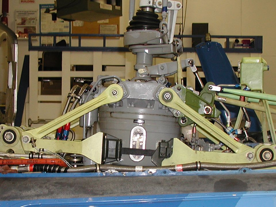
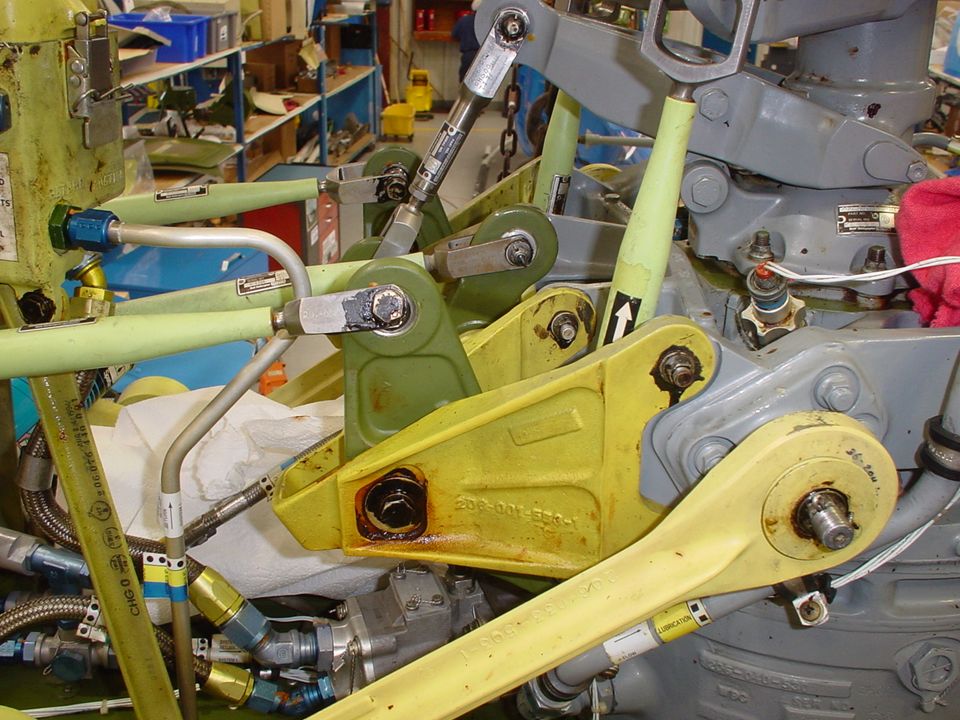
TRANSMISSION MOUNTS NODAL BEAM The transmission, mast, main rotor hub and blade assembly are supported by and isolated from the fuselage by the transmission mounts (nodal beam) and transmission restraint. This is accomplish- ed by use of four link attachments and two stop mounts bolted to the transmission. Attached to these are four link assemblies incorporating elastomeric bearings which are secured to the four support assemblies and the flexure assemblies.

23
The support assemblies are bolted to the cabin roof shell and cabin roof beam and contain elastomeric bearing and bushing members to isolate and balance vibration inputs from the rotor into the flexure assemblies. The flexure assemblies are the primary vibration isolating component that provides for a vibration free ride throughout the helicopters speed range. Tuning weights are bolted to the arm and flexure assemblies and provide for the fine tuning and balance of the transmission mounting system.

24
The transmission restraint limits movement of the transmission through the use of an elastomeric beating and bushing member which is secured to the transmission restraint support. The support is bolted to the cabin roof shell and cabin beam along with two drag pins. The two stop mounts that are bolted to the trans-mission are installed over the drag pins. The up stops mounted on the drag pins restrict the up movement of the transmission and all oscillatory movement.

25
LINK ATTACHMENTS SUPPORT ASSEMBLIES ELASTOMERIC BEARINGS FLEXUREASSEMBLY

26
RESTRAINT DRAG PINS STOP MOUNTS RESTRAINTSUPPORT

27
SUPPORTASSEMBLIES

29
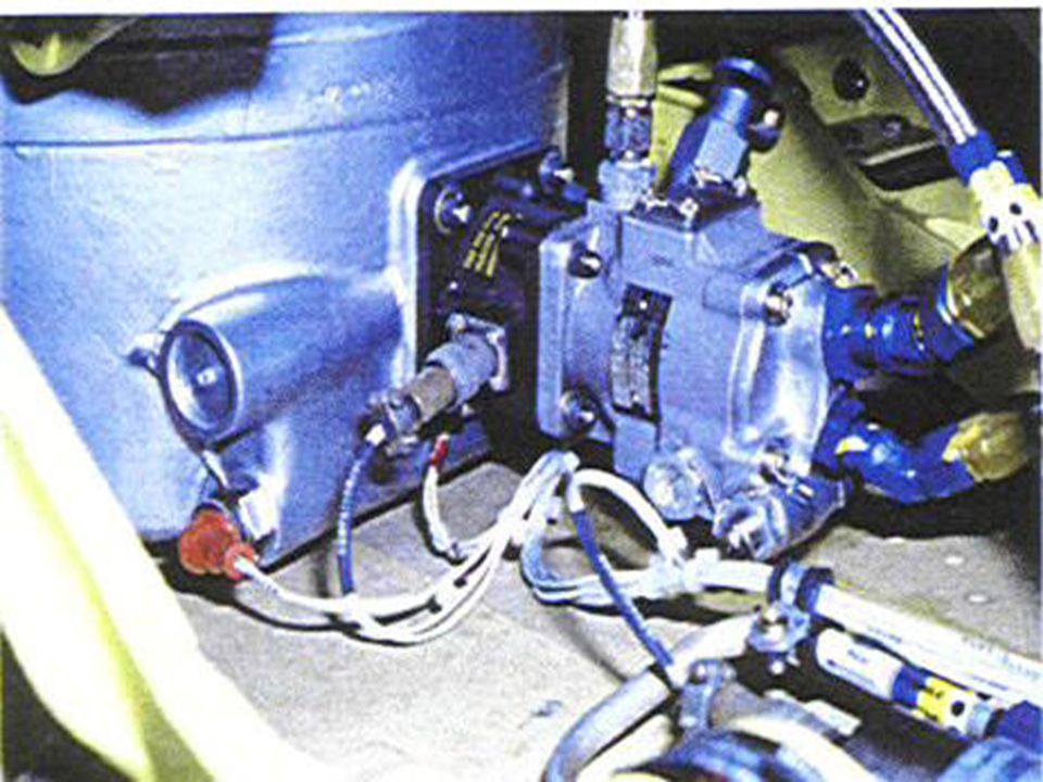
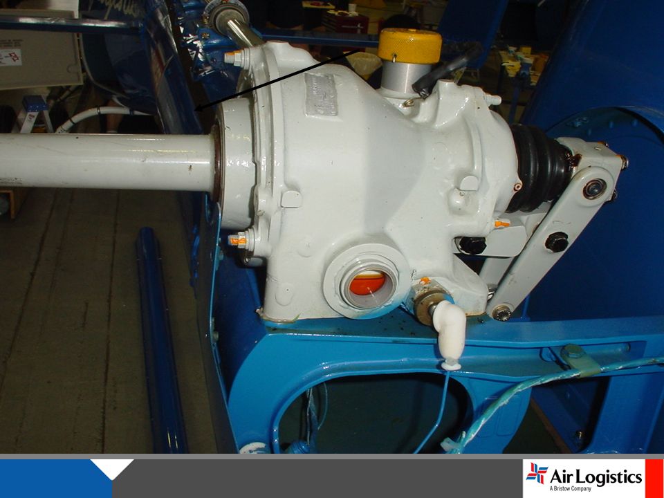
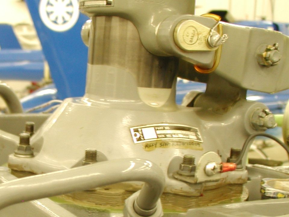
TRANSMISSION The main transmission is mounted forward of the engine and is coupled to the engine by means of a short drive shaft. Basically, the transmission is a reduction gearbox which transmits engine power, at reduced RPM, to the main rotor by means of a spiral bevel gear and a planetary gear stage. The transmission incorporates a self- contained lubrication system with an oil cooler.

30
Accessory mounting pads and drives are provided on the transmission for the hydraulic pump and rotor tachometer. The transmission is a two stage reduction of 15.23 to 1.0 (6000 RPM to 394 RPM).
..")
31
TRANSMISSION MAIN CASE

32
TRANSMISSION UPPER CASE

33
PLANETARY GEAR SUN GEAR ACCESSORY DRIVE GEAR INPUT DRIVE (6016 RPM) OIL PUMP OUTPUT 395 RPM (3.26 TO 1.0)
 OIL PUMP OUTPUT 395 RPM (3.26 TO 1.0)")
34
HYDRAULICPUMP ROTOR TACH XMSN OIL PUMP LOWER ELECT CHIP DETECTOR UPPER DETECTOR SUMP OIL SCREEN

35
MAST ASSEMBLY

36
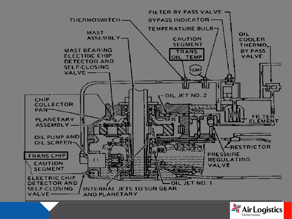
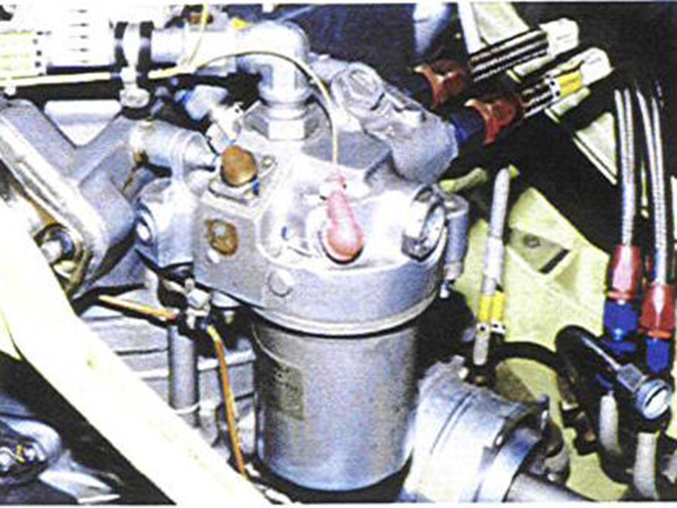
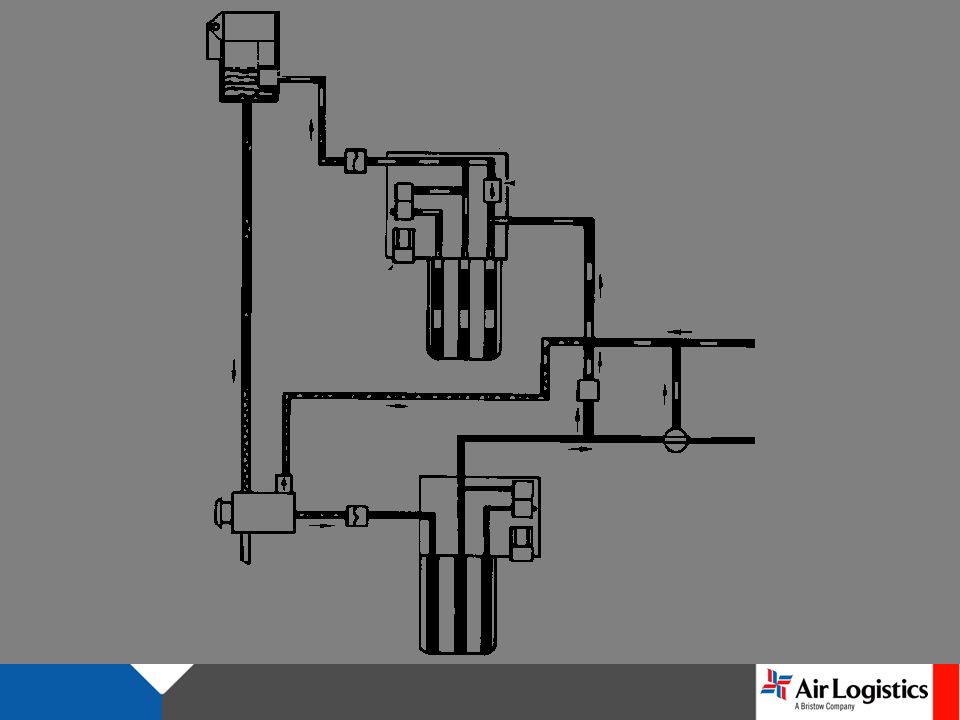
TRANSMISSION LUBRICATION SYSTEM

37
TRANSMISSION

38
XMSN OIL SYSTEM BEGINS TO CLOSE 66˚ C, SOME OIL TO COOLER MOST BYPASSES FULLY CLOSED 81˚ C, ALL OIL THRU COOLER,

39
TRANSMISSION LUBRICATION SYSTEM

41
OPEN UNTIL 66˚C CLOSED 81˚C

45
If not seated properly plug will block inlet to trans oil pump Actually BH206B pictured

46
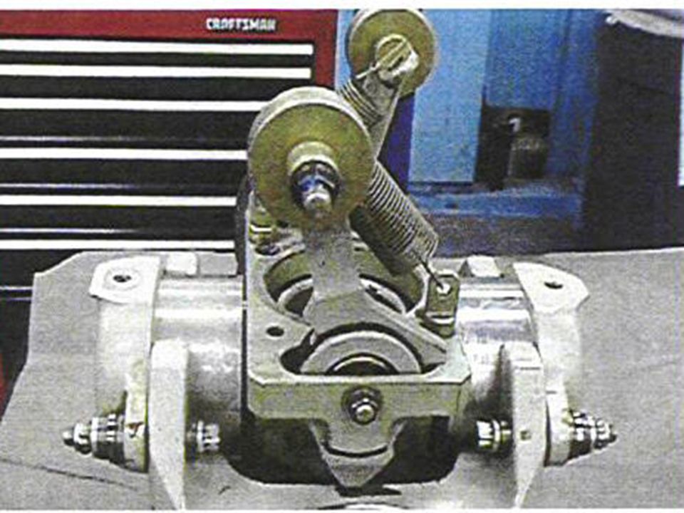
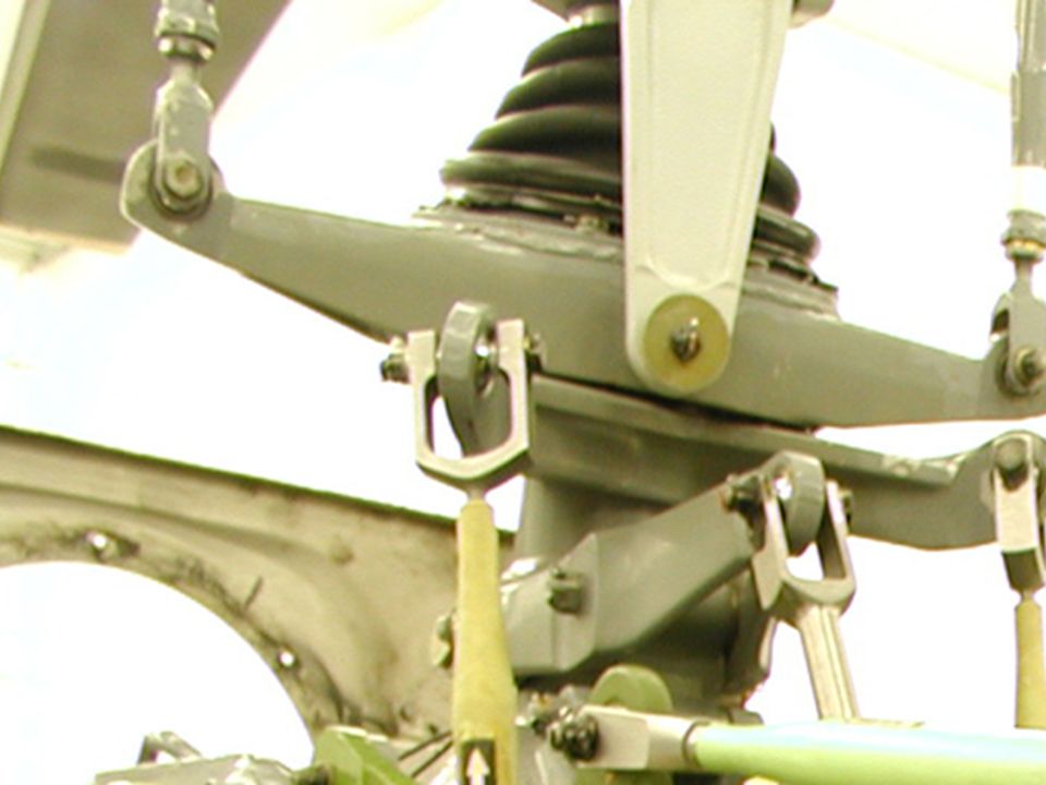
SWASHPLATE AND SUPPORT ASSEMBLY The swashplate and support assembly encircles the mast directly above the trans-mission and is mounted on a universal support (pivot sleeve) which permits it to be tilted in any direction. Movement of the cyclic control stick results in a corresponding tilt of the swashplate and the main rotor. Movement of the collective pitch lever actuates the sleeve assembly which raises or lowers the swashplate and transmits collective control to the main rotor. The cyclic controls are properly coordinated with collective control by action of the mixing lever at the base of the control column.

47
MAST COLLAR SET BOOT OUTER RING INNER RING COLLECTIVELEVER SUPPORT IDLERLEVER IDLERLINK SPHERICALBEARING

48
MAIN ROTOR HUB AND BLADE ASSEMBLY The main rotor assembly is a two bladed, semi-rigid, see-saw type rotor with underslung mounting. The blades are mounted in the hub assembly grips with through bolts, which have hollow shanks for installation of weights to balance the hub. After balancing, the bolts must be kept with their respective rotor hub grips. Blade alignment is accomplished by adjust-ment of blade latches, which engage the root end of the blade.

49
The blade grips are retained on the hub yoke by means of tension-torsion strap assemblies. Changes in blade pitch angle are made by rotating the grips on the yoke journals; each grip has two pitch change bearings. The rotor blades are all metal, five piece assemblies consisting of an extruded aluminum alloy nose block, aluminum alloy trailing edge, and an aluminum honeycomb filler. A flap restraint mechanism is installed on the main rotor hub. The flap restraint assembly serves to prevent excessive flapping of the main rotor during starting and shutdown.

50
FLAPRESTRAINT RETENTIONNUT PILLOWBLOCK BLADE BOLT TRUNIONBEARING BLADEGRIP PITCHHORN LATCHBOLT SPLITCONES PITCH CHANGE CONTROL ROD YOKE

53
PILLOW BLOCK ASSEMBLY

54
BLADE GRIP ASSEMBLY

55
TENSION TORSION STRAP ASSEMBLY

56
BLADE BOLT ASSEMBLY

57
MAIN ROTOR BLADE

59
STATIC LOADING 34”MAXIMUMDEFLECTION 90 LBS MAXIMUM BLADE LOAD

60
TAIL ROTOR GEAR BOX The tail rotor gearbox contains two spiral bevel gears positioned at ninety degrees to each other. The direction of drive is changed ninety degrees and there is a speed reduction of 2.35 to 1.0 at the gearbox. The gearbox housing is magnesium and is attached to the tail boom with four studs, nuts, washers, and two dowel pins for alignment. The gearbox assembly includes a breather-type filler cap, oil level sight gage and a combination electrical chip detector and self-closing valve.

61
The self-closing valve makes it possible to check the electric chip detector for metal particles without draining oil from the gearbox. The self-closing valve also serves as a drain plug for gearbox oil. The tail rotor assembly is mounted on the gearbox output gear shaft. A portion of the tail rotor pitch controls are mounted on the gearbox and pass through the output gear shaft.

62
TAIL ROTOR GEARBOX

63
TAIL ROTOR GEAR BOX CROSS-SECTION

65
TAIL ROTOR The tail rotor hub and blade assembly consists of an aluminum alloy forged yoke and stainless steel blades. The blades are mounted in the yoke by means of spherical bearings which are mounted in the grip tangs on the pitch change axis. The grip tangs have a 4 o twist incorporated in them to give addition anti-torque control. The blade assembly is mounted on the 90 degree gearbox shaft by means of a splined trunnion, mounted in bearings in the yoke, to provide a flapping axis for the assembly.

66
Ballast stations located at the inboard trailing edge and at the tip of the blades are provided for master balance of the blades; weights used in these locations are determined when the blade is manufactured. At time of assembly, and before installation, the assembly must be chordwise and spanwise balanced.

67
TAIL ROTOR

68
TAIL ROTOR HUB AND BLADE ASSEMBLY

69
TAIL ROTOR INSTALLATION

70
CROSS-SECTION

71
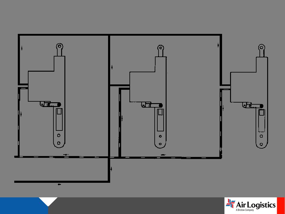
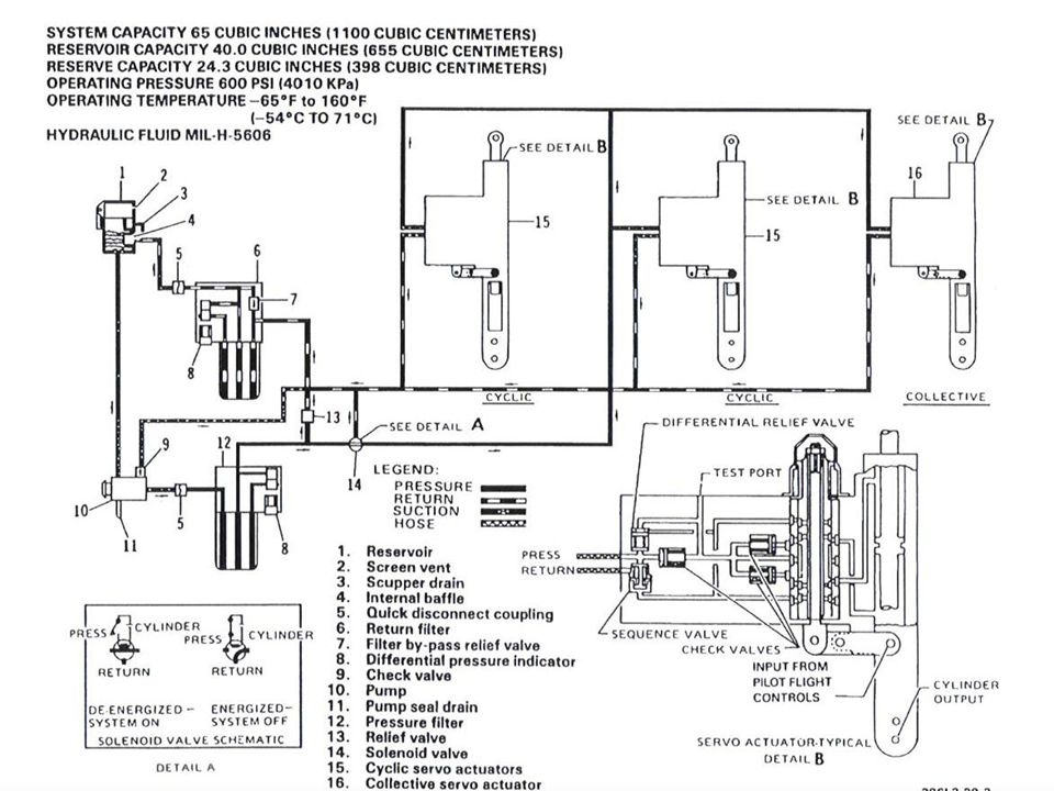
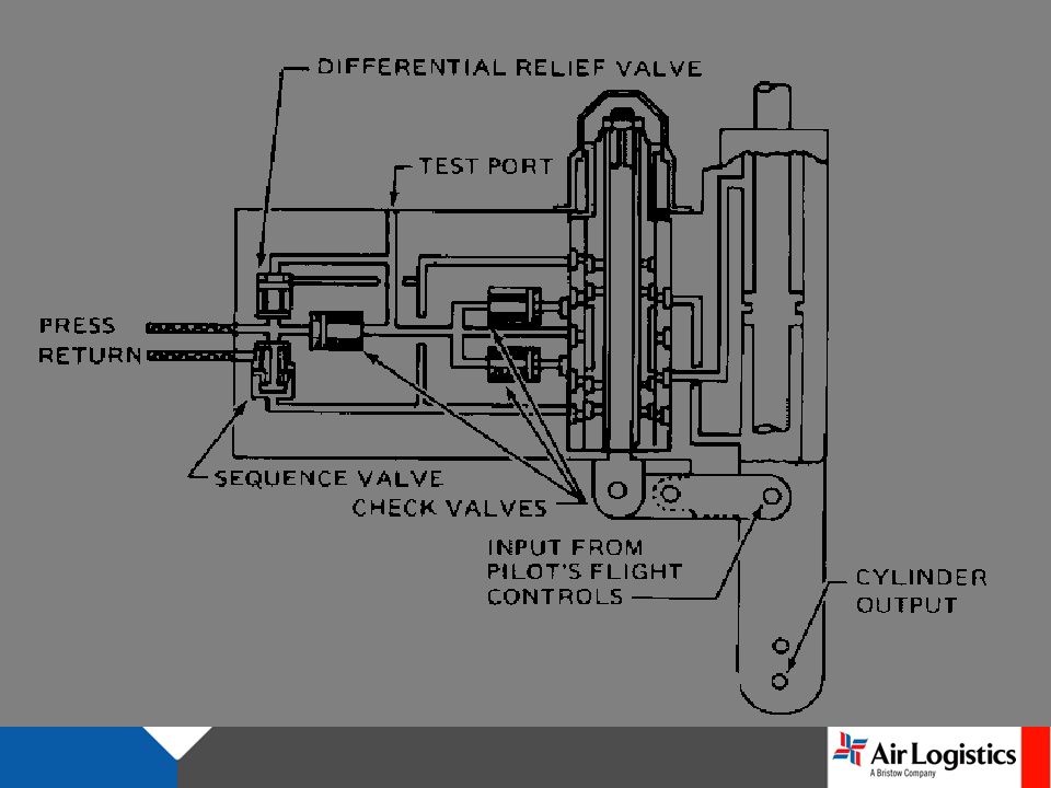
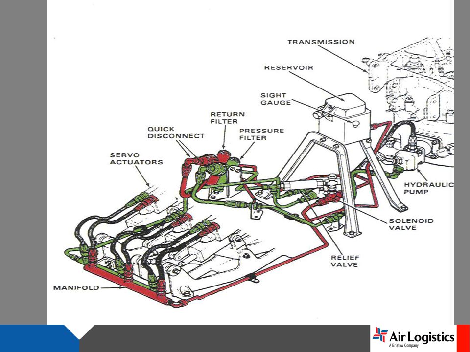
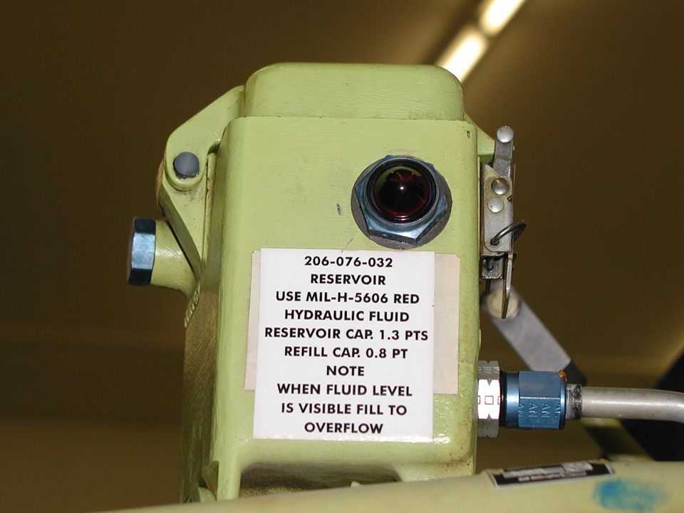
HYDRAULIC SYSTEM The transmission driven hydraulic pump provides for fully boosted flight controls being available during autorotative flight. The pump is mounted on and driven through the rotor tachometer generator. The pump is a variable delivery type and provides system pressure of 600 +/- 25 psi. The hydraulic reservoir is made from magnesium alloy. The reservoir is mounted on a brace and support forward of the transmission, and above the hydraulic pump assembly.

72
Fluid level may be observed through a transparent plastic sight glass in the left side of the reservoir. Two filter assemblies are installed in the system; one in the pressure supply line, and on in the return line. The return line filter assembly incorporates a bypass valve. A pressure relief valve is installed between the pressure line and the return line to protect the system from excessive pressure.

73
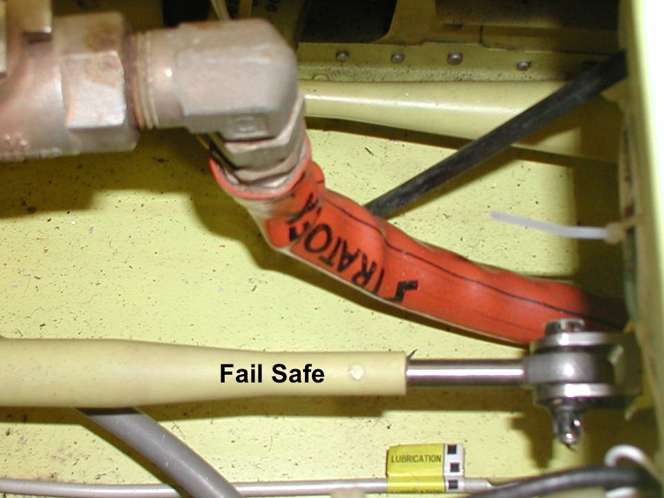
If the system exceeds the normal pressure range, the relief valve will bypass the high pressure back to the reservoir. When the pressure reaches 670-770 psi. The hydraulic system "on and off" solenoid valve, mounted on the cabin roof is a "fail safe" type, spring loaded to "normally open" position. The only method to turn the system off is the application of electrical power through the "HYDRAULIC SYSTEM" switch on the instrument panel.

84
FLIGHT CONTROLS The flight control systems are mechanical linkages, actuated by conventional controls, and are used to control flight attitude and direction. The cyclic control and collective control systems have hydraulic boost. A synchronized elevator is linked into the fore and aft control system at the cyclic torque tube.

85
The controls are routed beneath the cockpit seats, aft to the center of the helicopter, and up through the control column to the cabin roof. Access doors located on the aft side of the control column and seat panels are provided for inspections of control components, and for maintenance accessibility. Cyclic and collective controls are routed to the main rotor blades through the swashplate. The directional controls are routed through the tail boom to the tail rotor.

86
CYCLIC CONTROL LINKAGE

87
FRICTIONADJUSTMENT

88
COLLECTIVECONTROLLINKAGE

89
COLLECTIVE FRICTION ADJUSTMENT

90
ANTI-TORQUE CONTROL LINKAGE

91
Mixing Lever

92
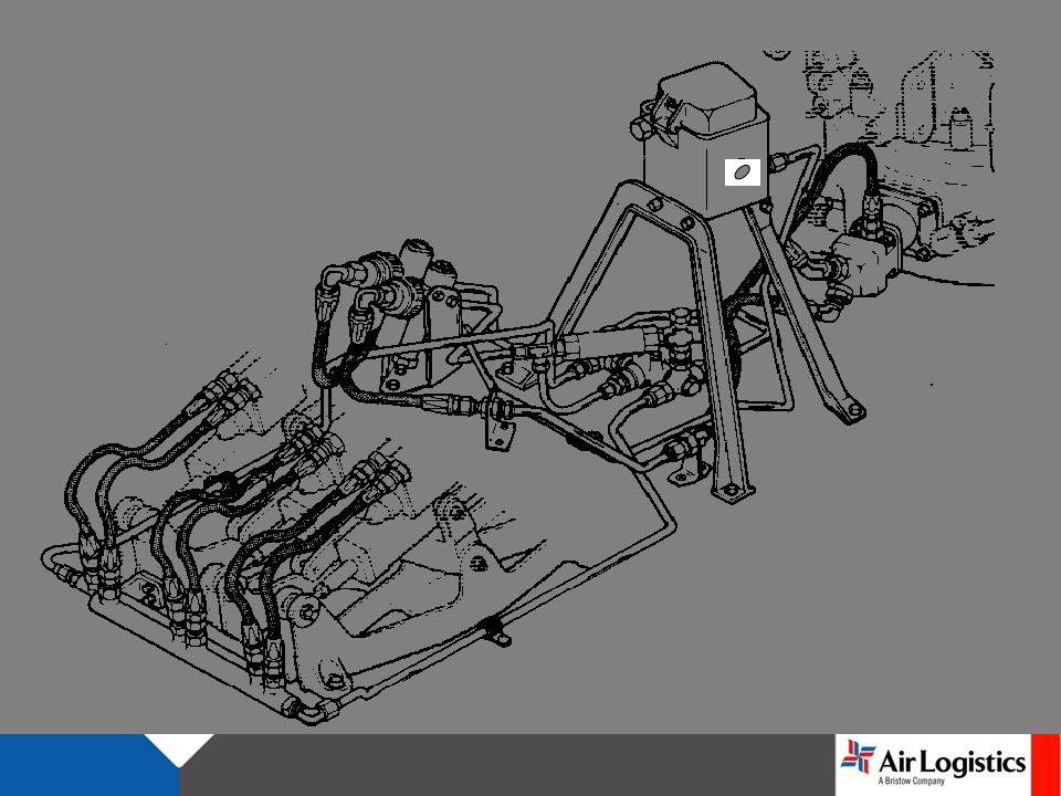
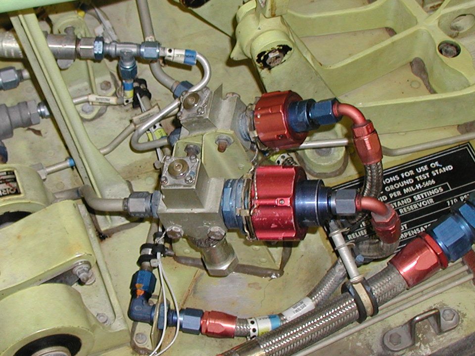
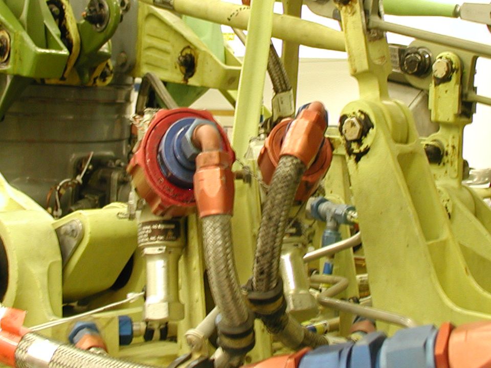
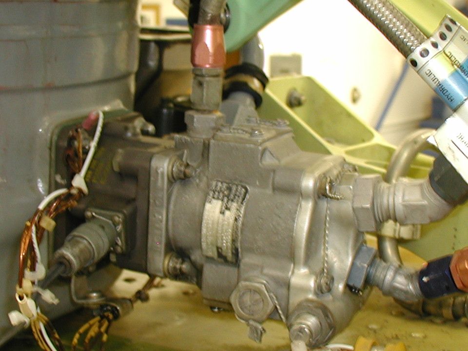
HYDRAULICSYSTEM

93
TRANSMISSION BELL CRANKS

94
Fail Safe

96
Pedal Weight

Similar presentations


>")

