Download presentation
Presentation is loading. Please wait.

1
TRACKING AND VERTEXING SUMMARY Suyong Choi Korea University

2
Outline Vertex/tracking detector for ILC Vertex detector for CLIC LCTPC

3
DEPFET

5
DEPFET Test Beam

6
DEPFET – Cooling Cooling Mockup and simulation tools used Belle-II (air + liquid cooling), ILC (air cooling) 1 m/s air flow needed for sufficient cooling 2 m deformation for 2 m/s, 0.7 m amplitude vibration ILC cooling Power pulsing exercised FEM analysis set up Port belle-2 mock up to ILC By DBD, full measurements + simulations Mockup for Belle II
, ILC (air cooling) 1 m/s air flow needed for sufficient cooling 2 m deformation for 2 m/s, 0.7 m amplitude vibration ILC cooling Power pulsing exercised FEM analysis set up Port belle-2 mock up to ILC By DBD, full measurements + simulations Mockup for Belle II")
7
CPS – CMOS PIXEL SENSOR

8
CPS for ILD-VXD

9
CPS

11
FPCCD – FINE PIXEL CCD

12
FPCCD 2 nd FPCCD readout ASIC Total noise 16e < 30e prototype power consumption: 30.9 mW/ch > 6 mW/ch 3 rd FPCCD readout ASIC Changes to analog and digital readout Process: 0.35 m to 0.25 m 5.4 mW/ch DNL and INL improved to within 1LSB and 0.38% Plan 2 nd Prototype - test using radiation sources 3 rd prototype – chip arrival in Oct

13
Cooling of FPCCD Vertex Detector To minimize charge transfer inefficiency due to radiation damage cooling to -40 C is optimal Use two-phase CO 2 Large latent heat of C02 Smaller flow rate Cooling system test mock up No condensation Heat penetration 20W/m measured Plans Cooling test of dummy ladder/end- plate Circulating system CO 2 cooling blow system between -40C and 15 C

14
FORWARD TRACKING

15
Fiber Bragg Grating sensor for FTD Temperature and humidity measurement with FBG Sensitive to strain and deformations

16
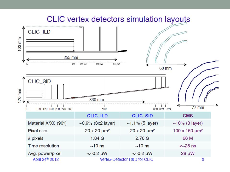
CLIC VERTEX DETECTOR

17
VTX requirements for CLIC Post CDR design Minimize cabling, vertical integration inactive regions, Lorentz angle

18
Vertex Detector R&D for CLIC

19
Simulations Sensor Charge collection Charge sharing Signal rise time Backgrounds 5~10 hits per cluster for innermost vertex barrel layer from incoherent pair backgrounds 0.5%~1% occupancies B=5T

20
Power and Cooling

21
LCTPC

22
LCTPC Status

23
LCTPC Prototypes LP1 test beam at DESY (1-6 GeV electron beam) LP2 – upgrade from LP1 Magnet using cryocoolers new end plate(realistic material budget) new cage field (end of 2012) Simulation suggests ion back-drift in amplification cause 60 micron distortion. Gating system may be needed. Plans Upgraded test beam facility to test momentum resolution Hadron beam to test multitrack environment

24
BACKUP

25
DEPFET

26
FPCCD vertex detector Fine Pixel CCD Pixel size ~ 5 m Fully depleted epitaxial layer Read out between trains (No power pulsing) FPCCD vertex detector Double-sided ladder 1.6x10 10 pixels Sensors and front-end ASICs inside a cryostat Power consumption > 50W inside the cryostat Readout ASIC Total power < 100W 10 Mpix/sec Noise + ADC accuracy < 30e (signal size 500 e) FPCCD prototype 26
 FPCCD vertex detector Double-sided ladder 1.6x10 10 pixels Sensors and front-end ASICs inside a cryostat Power consumption > 50W inside the cryostat Readout ASIC Total power < 100W 10 Mpix/sec Noise + ADC accuracy < 30e (signal size 500 e) FPCCD prototype 26")
27
CO 2 cooling for FPCCD VTX Cooling tube is attached to VTX end-plate and heat removed by conduction through CFRP ladder Return line of CO2 will be used to cool the electronics outside the cryostat (~200W/side) Inner support tube should be air-tight and filled with dry air/nitrogen in order to prevent condensation on the CO2 tube 27
 Inner support tube should be air-tight and filled with dry air/nitrogen in order to prevent condensation on the CO2 tube 27")
28
Fiber Bragg Grating Monitoring Fiber Bragg Grating sensor principle Environmental and structural monitor Low material budget Immune against high EM fields Can be used in high and low temp. Suitable in radiation environment

30
Cooling Power: 500W (50mW/cm 2 ) Forced dry air – baseline for barrel region
 Forced dry air – baseline for barrel region")
Similar presentations


 Vertex Detector for SuperBelle Ariane Frey, Max-Planck-Institut für Physik München Contents: Software framework Simulation.>")


mrad: The Outer Tracker: covers the large.>")


 The University of Melbourne.>")


